manuals.online logo
Brands
  1. Home
  2. •
  3. Brands
  4. •
  5. Digicom
  6. •
  7. Modem
  8. •
  9. Digicom SNM15 User manual

Digicom SNM15 User manual

SNM15
OPERATION MANUAL
SNM15 rev.1.0 del 07/91 COD.7D0548
All rights reserved; no part of this publication may be
reproduced, stored in a retrieval system, or trasmitted
in any form or by any means, electronic, otherwise,
without the prior written permission of the publishers.
The contents of this booklet may be modified without
prior permission.
Every possible care has been taken in testing and
putting together all the documentation contained in
this booklet, however DIGICOM can not take any
responsability brought by the use of this booklet.
INDEX
INTRODUCTION 1.1
OVERALL FEATURES 1.1
Mechanical Dimensions 1.1
Environmental Conditions 1.2
Mains Power Supply 1.2
Analog Interface 1.5
Control and Warning Devices 1.7
FUNCTIONAL FEATURES 2.1
Operational Modes 2.1
Error correction and data compression 2.2
MNP 2.3
CCITT V.42 and V.42bis 2.6
INSTALLATION 3.1
introduction 3.1
Connection to the DTE Data Terminal 3.1
Connecting to the Telephone Line and Telephone 3.1
Operational Test 3.3
USE OF THE MODEM 4.1
introduction 4.1
Control and worning devices 4.1
Control Devices on the Front Panel 4.1
Warning Devices 4.3
AT commands 4.4
Command Buffer 4.5
Auto-Baud and Auto-Parity Detection 4.6
Data length 4.6
AT COMMAND SET DESCRIPTION 5.1
LIST OF THE MESSAGES IN SHORT AND EXTENDED FORMS 5.7
Default configuration 5.24
V.25 bis 6.1
Introduction 6.1
Duties of the DTE 6.1
Definitions and Operational Modes 6.2
ASYNCHRONOUS V.25BIS COMMANDS 6.8
Separators 6.12
ASINCHRONOUS V.25BIS INDICATIONS 6.13
SYNCHRONOUS V.25BIS COMMANDS 6.20
SYNCHRONOUS V.25BIS INDICATIONS 6.21
Line procedures 6.22
Default configuration of the commands from AT to V.25bis 6.22
Default configuration of S-Registers from AT to V.25bis 6.23
DIAGNOSTICS 7.1
Introduction 7.1
Enabling Remote Loop 2 7.1
Disabling Remote Loop 2 7.2
Enabling Loop 3 7.2
Disabling Loop 3 7.3
Resetting the Hardware 7.3
USE OF THE S-REGISTERS 8.1
introduction 8.1
Content of the Main Registers 8.1
Default configuration of the register 8.6
TYPICAL APPLICATIONS 9.1
introduction 9.1
Asynchronous connection without auto answer feature 9.1
Connection in V.22 and MNP 9.2
Synchronous connection 9.2
Appendix A
Dip-Switches Setting A.1
Terminal Emulation Program A.4
1.1
SNM15 Introduction
Digicom SpA
INTRODUCTION
OVERALL FEATURES
The SNM 15 modem is externally designed with a metal frame.
The cards are pulled out by pressing the lever located beneath the
front panel.
On the front panel there are indicating lights for the main interface
circuits, the operational condition of the modem and the operation
and test enabling switches.
On the rear panel there are the power supply cord, the protection
fuses and the mains switch. There are also the line connector and
the two ISO 2110 type female connectors to terminate the
DTE(s).
The modem is supplied together with the present manual with a
cable for the connection to the telephone plug.
Mechanical Dimensions
Width : 190 mm.
Height : 44 mm.
Depth : 266 mm.
Weight : 2 Kg.
1.2
SNM15 Introduction
Digicom SpA
Environmental Conditions
Operational temperature : from 0°C to +50°C
Storage temperature : from -20°C to +80°C
Relative moisture : from 5% to 92% non condensing
Mains Power Supply
Power supply voltage : 220 Vac. (-15% : +10%) frequency
47 : 63 Hz.
Consumption : 3 VA
Digital Interface
The modem is equipped with two data interfaces: MAIN PORT
and COMMAND PORT. The former can be used indifferently for
programming the modem and transmitting data to a remote
modem, the latter can only be used to program the modem.
Communication procedure : asynchronous Start/Stop serial
Character format : see table:
1 start bit 7 data bits even/odd 1 stop bit
1 start bit 7 data bits mark/space 1 stop bit
1 start bit 7 data bits no parity 2 stop bits
1 start bit 8 data bits no parity 1 stop bit
MAIN PORT : The connector marked by this
abbreviation is the main port of the
modem. By using this connector,
the initial functions of
programming and enabling
1.3
SNM15 Introduction
Digicom SpA
connection and the real primary
function of transmitting data are
performed. The latter function can
beperformedineithersynchronous
or asynchronous mode.
COMMAND PORT : This port can only be used to send
the commands to the modem. The
criteria: CTS, DSR, DCD, when
the port is active, are forced into a
working condition so as to allow
data to be transferred from the
DTE to the DCE and vice-versa.
Operational mode : In order to program and enable the
connection, the format is start-
stop asynchronous, whereas data
can be transmitted in either
asynchronous or synchronous
format.
Characters Code : the ASCII code is used for
programming, while there are no
limitations once it has been
connected, the BREAK signal is
also transferred according to the
CCITT V.22 standard.
Type of interface : In compliance with the CCITT
V.24/V.28 or EIA RS.232C
specifications, the 25 contact
female connectors conform to the
ISO 2110 standards.
1.4
SNM15 Introduction
Digicom SpA
Cont. Circuit Direction Mnem. Description
Conn. V.24 RS 232 DTE-SNM15Abbrev.
2 103 BA ————> TD Transmit data
3 104 BB <———— RD Receive data
4 105 CA ————> RTS Request to transmit
5 106 CB <————> CTS Clear to transmit
6 107 CC <———— DSR Modem ready
7 102 AB <————> SG Signal ground
8 109 CF <———— DCD Data carrier detect
9 - - <———— +12 V test voltage
10 - - <———— -12 V test voltage
11 - -
12 - -
13 - -
14 - -
15 114 DB <———— TC Internal transmission
clock
16 - -
17 115 DD <———— RC Reception clock
18 141 CN ————> L3 Request for loop 3
19 CCONF pin (see *M
command)
20 108.2 CD ————> DTR Data terminal ready
21 140 CF ————> RDL Request for remote Loop
22 125 CE <———— RI Ring Indication
23 112 CI <———— Speed section for DCE
(Note 1)
24 113 DA ————> ETC External transmission
clock
25 142 - <———— TI Active loop
Interface circuits
1.5
SNM15 Introduction
Digicom SpA
Note: contacts 11, 12, 13, 14 and 16 have been left free.
Transmitted data clock : in synchronous operation, the
modem needs a clock for data
transmission. This may be
generated by the modem (internal
clock) and supplied to the DTE via
the interface circuit C114. The
modem also accepts an external
timer (external clock) supplied on
circuit C113 of the interface,
provided that it has the tolerance
levels envisaged by the CCITT.
Received Data Clock : in synchronous mode, the modem
deals with timing the received data
on circuit C115.
Analog Interface
Transmitting support : 2 balanced wires per switched line
(private PABX exchange or public
PSTN network).
Transmission level : from -1 to -16 dBm that can be
adjusted by 1 dbm step.
Data carrier : V.21 300 bps FSK
V.22 1200 bps DPSK
V.22bis 2400 bps QAM
1.6
SNM15 Introduction
Digicom SpA
Threshold of the receiver : definitely OFF with a carrier level
(DCD) lower than -48 dBm;
definitely ON with a level at -43
dBm.
Call detector : frequency from 25 Hz to 50 Hz;
sensitivity 20 Veff or higher;
insensitivity 15 Veff or lower.
C125 (RI) delay : 500 ms ±100 ms compared to the
initial call voltage.
Answer tone : 2100 Hz ±1 Hz of the duration of
3.3 sec ±1 ms.
Automatic disconnection : within 30 seconds per failure to
synchronize with the
corresponding modem
(selectable); once connected, due
to loss of carrier, 700 ms
(selectable).
Type of call : can be selected to emit pulses
(decadic) or multi-frequency
(DTMF).
Recurrence frequency : 10 ±1 pulse/sec.
Open/close ratio : 40/60 ms.
Pause between bits : 800 ms ±50 ms.
1.7
SNM15 Introduction
Digicom SpA
Frequency tolerance : ±1% compared to nominal
frequencieslaiddownintheCCITT
Q23 recommendation.
Tone duration : 100 ms ±5 ms.
Control and Warning Devices
The control and warning devices with which SNM 15 is equipped
can be considered as auxiliary devices since the functions played
by these devices are already present in the form of commands and
communication protocol messages.
They are particularly useful in the case of manual calls or loop
tests for the switches.
Controls on the Front Panel
DATA answer/calling
TEST loop 2/3
Warning Lights on the Front Panel
PWR modem being fed
C108 DTR Data terminal ready
C107 DSR Modem ready
C103 TD Transmit data
C104 RD Receive data
C109 DCD data carrier detector
C142 TEST modem in loop
LINE modem connected to the line
1.8
SNM15 Introduction
Digicom SpA
Controls on the Rear Panel
ON/OFF power supply switch on/off
PWR C108 C107 C103 C104 C109 C142 LINE
Front view of SNM 15
Rear view of SNM 15
2.1
SNM15 Functional Features
Digicom SpA
FUNCTIONAL FEATURES
Operational Modes
The environments V.25bis and AT that live together in the same
SNM 15 modem allow you to operate, at different times, in one
or another mode.
When it is switched on, the system directly goes into the last
environment in which you operated, by initializing the modem
with the values previously saved in the non-volatile memory.
When it is first switched on or for any losses of the programmed
values, the modem will be initialized with the default values and
then go into the “AT” environment.
The V.25bis is enabled by the command “AT*Vn” (see command
“*V”). With parameter “n”, you select the control of V.25bis
C108/2 (AT*V=0) asynchronous or V25bis HDLC (AT*V2).
It is compulsory to use the AT&W command, if you wish to save
any possible alteration of the parameters, enabled in the “AT”
mode before changing mode (fig. 3).
The complementary command: HAY, allows you to pass from the
“V.25bis” mode to the “AT” mode.
Note: it is possible to perform a hardware reset of the modem
which loads the factory configuration: switch on the modem
keeping the DATA button pressed for some seconds.
2.2
SNM15 Functional Features
Digicom SpA
Error correction and data compression
Transmission optimizing techniques have been introduced to
ensure faultless data transmission.
These techniques are made up of a line protocol acting as a logical
means of transport with functions of supervising the transmitting
device and optimizing the data transmission speed.
SNM15 implements 2 error correction tecniques: MNP4 and
CCITT V.42.
When using the error check it is indispensable to use the flow
control (see command &U); in fact, if the features of the line when
being connected become worse, the modem will be forced to
retransmit many blocks several times.
This might lead to the saturation of modem buffer (especially if
there is continuous traffic coming from the DTE) and without
appropriately handling the flow control (CTS or XON and
XOFF) many of the data being transmitted that are parked in the
DCE, would be overwritten by data continuously emitted by the
associated DTE.
In the DIGICOM SNM 15 modem V.42/V.42bis and MNP
functions are available in both the AT and the V.25bis
(asynchronous) environments; the configuration and enabling/
disabling stages can be controlled in the AT mode.
2.3
SNM15 Functional Features
Digicom SpA
MNP
3 classes of operation as well as a series of options have been
defined.
Classes 1 & 2 make use, on line basis, of an asynchronous
protocol, whereas class 3 is supported by a HDLC type
synchronous protocol.
This allows you to check the presence of errors in the transmission
blocks (due to interference present on line) and to request the
wrong blocks received to be transmitted again.
Before listing the features of the MNP supported by the SNM 15
modem, we will give a brief informative summary of the 5 levels
defined by this protocol.
MNP CLASS 1
Asynchronous error correction protocol, half-duplex or byte
oriented; it is now practically out of use with a line efficiency equal
to 70% of the nominal value of the set speed on a RS232 interface
level.
MNP CLASS 2
Asynchronous error correction protocol, full-duplex and byte
oriented with a line efficiency equal to 84% of the nominal value.
MNP CLASS 3
Synchronouserrorcorrection protocol, full-duplex and bit oriented
with a structure similar to the HDLC.
Its line efficiency is equal to about 108 of the nominal value, thus
with a total increase of 8%.
2.4
SNM15 Functional Features
Digicom SpA
MNP OPTION 4
This option introduces two new features in the world of error
correction:
Adaptive Packet
The transferred packets are optimized, on the basis of the features
of the transmitting device. During the transfer, the modem
monitors the line, by detecting the amount of errors (and thus the
qualityofconnection)andconsequentlyhastheeffectofoptimizing
the length of the packets (from 1 to 256 characters, in dynamic
mode). If the data channel has relatively few errors, the MNP will
automatically increase the length of the packets, thus obtaining
greater efficiency, and vice-versa should there be errors.
Data Optimizing
This only eliminates the rounded off characters present in the data
field.
Here its line efficiency reaches 120% of the nominal value.
MNP OPTION 5
Option 5 allows you to optimize the transmission packet, by
taking advantage of a data compression achieved by an adaptive
algorithm in real time.
Its line efficiency reaches 200% of the nominal value.
2.5
SNM15 Functional Features
Digicom SpA
SNM 15 can operate with the following configurations:
CLASS (with &E=4 or 5)
2
3
2 + 4
3 + 4
CLASS (with &E=4 or 5 and *E=1)
2 + 5
3 + 5
2 + 4 + 5
3 + 4 + 5
This makes it completely compatible with all modems having a
MNP 5 or lower type correcting function.
Obviously the choice of the level exclusively depends on the
features of the modem and occurs AUTOMATICALLY (see
column &E 4 or 5) when it is connected, by establishing the
maximum common level for both units.
Remember that option 5 can be enabled or disabled independently
at one of the classes mentioned above, therefore classes 2 and 3
together with option 4 cannot be set manually by the operator, but
they are automatically selected when it is negotiating with the
remote DCE.
2.6
SNM15 Functional Features
Digicom SpA
CCITT V.42 and V.42bis
V.42 and V.42bis are standard error correction and data
compression tecniques stated by CCITT; V.42bis allows to have
a more efficient data compression respect MNP5; infact the line
efficiency can reach 400% of the nominal value.
3.1
SNM15 Installation
Digicom SpA
INSTALLATION
INTRODUCTION
This part contains some indications for the preinstallation of the
modem as well as the operational procedure for its correct
mechanical and electrical installation.
Connection to the DTE Data Terminal
It is better to make sure that the data interface of the DTE to be
connected to the modem complies with the CCITT V.24 or V.28
recommendations.
The circuits used with the modem are given in the introduction.
Please remember that the V.28 standard recommends that the
interface cables must be no longer than 15 m.
The interface connector is a standardized 25 contact female ISO
2110 connector.
Connecting to the Telephone Line and Telephone
The line connectors to match the telephone line and the telephone
are located on the rear part of the modem.
A terminated cable with a RJ11 connector is supplied together
with the modem allowing you to quickly connect the modem to
the telephone socket. On the RJ11 connector, the central wires
are the line, the external ones are to be connected to the telephone.
3.2
SNM15 Installation
Digicom SpA
INSTALLATION OF THE SNM 15
COMMAND PORT MAIN PORT
RJ11
TO DTE
DTE
telephon
plug
RJ11
SNM15
RJ11

Other Digicom Modem manuals

Digicom HSDPA User manual

Digicom

Digicom HSDPA User manual

Digicom BlueGATE User manual

Digicom

Digicom BlueGATE User manual

Digicom Pocket GPRS Power User manual

Digicom

Digicom Pocket GPRS Power User manual

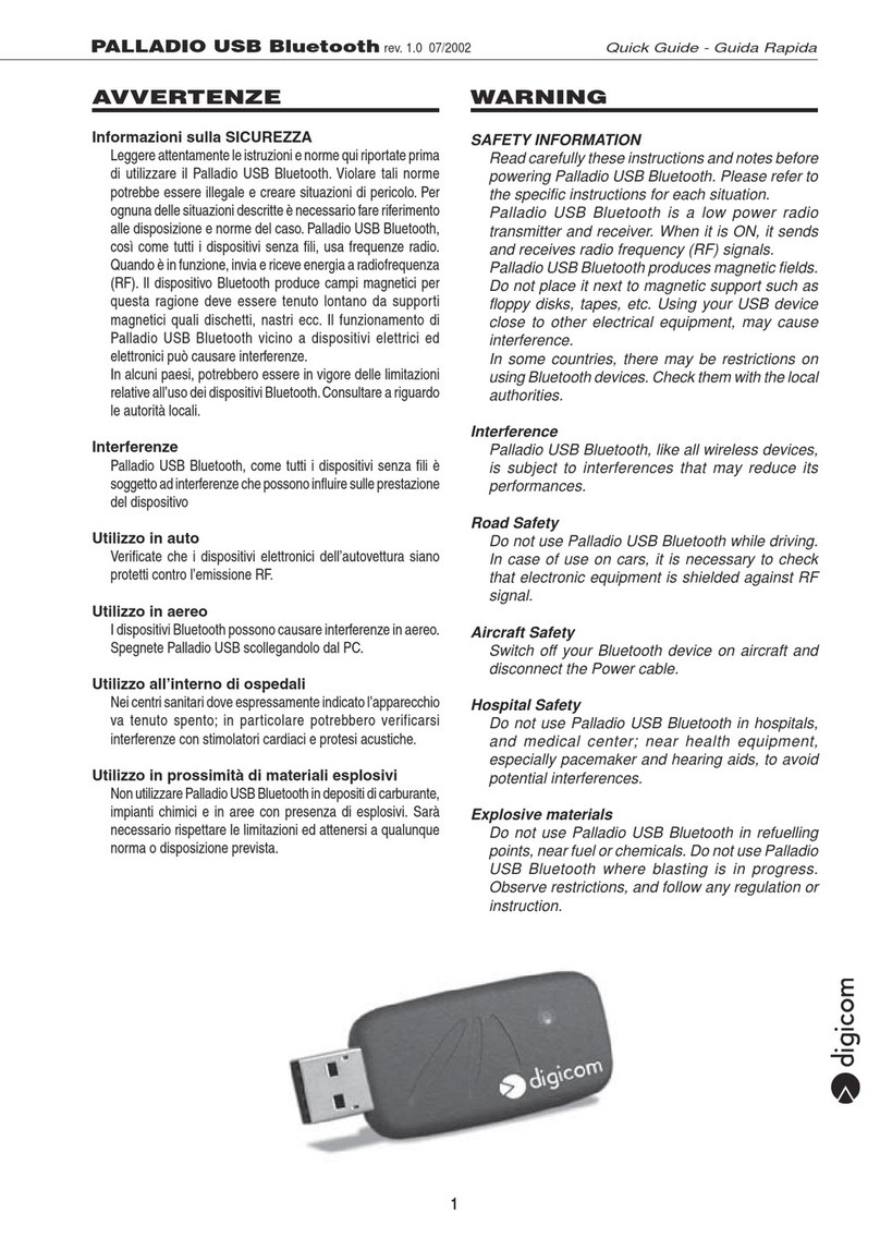
Digicom Palladio USB Bluetooth User manual

Digicom

Digicom Palladio USB Bluetooth User manual

Digicom Gsm Bulk DCS1800 User manual

Digicom

Digicom Gsm Bulk DCS1800 User manual

Digicom Botticelli Web 8E4079 User manual

Digicom

Digicom Botticelli Web 8E4079 User manual

Digicom SNM70 User manual

Digicom

Digicom SNM70 User manual

Digicom LCM16P User manual

Digicom

Digicom LCM16P User manual

Digicom Tintoretto LAN Plus ISDN LAN Modem User manual

Digicom

Digicom Tintoretto LAN Plus ISDN LAN Modem User manual

Digicom GPRS Bulk Micro QB User manual

Digicom

Digicom GPRS Bulk Micro QB User manual

Digicom COMSPHERE 3910 User manual

Digicom

Digicom COMSPHERE 3910 User manual

Digicom Tintoretto LAN+ User manual

Digicom

Digicom Tintoretto LAN+ User manual

Digicom WinModem V.92 User manual

Digicom

Digicom WinModem V.92 User manual

Digicom Tintoretto User manual

Digicom

Digicom Tintoretto User manual

Digicom HDSL User manual

Digicom

Digicom HDSL User manual

Digicom SNM46F User manual

Digicom

Digicom SNM46F User manual

Digicom 3G Modem USB Internal User manual

Digicom

Digicom 3G Modem USB Internal User manual

Digicom MTL01 User manual

Digicom

Digicom MTL01 User manual

Digicom Michelangelo Gateway User manual

Digicom

Digicom Michelangelo Gateway User manual

Digicom Pocket GPRS Micro Industrial User manual

Digicom

Digicom Pocket GPRS Micro Industrial User manual

Digicom pocket GSM User manual

Digicom

Digicom pocket GSM User manual

Digicom SNM50 User manual

Digicom

Digicom SNM50 User manual
Digicom Palladio USB Bluetooth User manual

Digicom

Digicom Palladio USB Bluetooth User manual

Digicom Tiziano 56 Memory User manual

Digicom

Digicom Tiziano 56 Memory User manual

Popular Modem manuals by other brands

Traverse Pulsar user manual

Traverse

Traverse Pulsar user manual

ESTeem 195H user manual

ESTeem

ESTeem 195H user manual

D-Link DSL-320B user manual

D-Link

D-Link DSL-320B user manual

Aztech DSL 300P Easy start

Aztech

Aztech DSL 300P Easy start

Draytek Vigor130 user guide

Draytek

Draytek Vigor130 user guide

Robustel GoRugged M1000 USB user guide

Robustel

Robustel GoRugged M1000 USB user guide

US Robotics USR802972B-OEM datasheet

US Robotics

US Robotics USR802972B-OEM datasheet

NETGEAR AC1750 datasheet

NETGEAR

NETGEAR AC1750 datasheet

Hughes Network Systems HN9000 installation guide

Hughes Network Systems

Hughes Network Systems HN9000 installation guide

Creative DE5773 user guide

Creative

Creative DE5773 user guide

Zain Wiyana Connect 4g e-GO quick start guide

Zain

Zain Wiyana Connect 4g e-GO quick start guide

Belkin F5D7630-4A user manual

Belkin

Belkin F5D7630-4A user manual

Manhattan 154109 instructions

Manhattan

Manhattan 154109 instructions

D-Link DWA-123 user manual

D-Link

D-Link DWA-123 user manual

Robustel GoRugged M1000 user guide

Robustel

Robustel GoRugged M1000 user guide

Cricket A605 EVDO user manual

Cricket

Cricket A605 EVDO user manual

Global Telecom Corp GLU-194M Quick user guide

Global Telecom Corp

Global Telecom Corp GLU-194M Quick user guide

Optus ADSL2+ WIFI MODEM Guide to installing

Optus

Optus ADSL2+ WIFI MODEM Guide to installing

manuals.online logo
manuals.online logoBrands
  • About & Mission
  • Contact us
  • Privacy Policy
  • Terms and Conditions

Copyright 2025 Manuals.Online. All Rights Reserved.