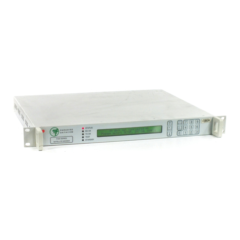
Paradise Datacom Vision Series User manual

Issue 8.0.13, 1 July 2009
2009
EN 55022 - Class B
EN 55024
EN 60950
Paradise Datacom Ltd. Paradise Datacom LLC
1 Wheaton Road 328 Innovation Blvd.
Witham, Essex, CM8 3UJ, England. State College, PA 16803, U.S.A.
Tel: +44(0)1376 515636 Tel: +1 814 238 3450
Fax: +44(0)1376 533764 Fax: +1 814 238 3829
http://www.paradisedata.com
Copyright © 2008-2009 Paradise Datacom Ltd. All rights reserved.
Installation and Operating Handbook for
Vision Series Satellite Modems

Vision Series Installation and Operating Handbook
ii
Table of Contents
Chapter 1
Welcome.....................................................................................................1-1
Chapter 2
About This Handbook...............................................................................2-1
2.1
Conventions ............................................................................................................2-1
2.2
Trademarks .............................................................................................................2-1
2.3
Disclaimer................................................................................................................2-1
2.4
GNU General Public Licence..................................................................................2-1
Chapter 3
Safety Information ....................................................................................3-1
3.1
Safety ......................................................................................................................3-1
3.2
Environmental .........................................................................................................3-1
3.3
Installation ...............................................................................................................3-1
Chapter 4
Electromagnetic Com patibility................................................................4-1
Chapter 5
Installation.................................................................................................5-1
5.1
Unpacking ...............................................................................................................5-1
5.2
Visual Inspection .....................................................................................................5-1
5.3
Getting Started ........................................................................................................5-1
5.4
Pow er Up.................................................................................................................5-1
Chapter 6
Introduction...............................................................................................6-1
6.1
Overview .................................................................................................................6-1
6.2
Hardw are Options ...................................................................................................6-2
6.2.1
Quad ASI Option Card ....................................................................................6-2
6.2.2
IP Traffic Option Card .....................................................................................6-2
6.2.3
Optional L-band BUC Pow er Supplies ...........................................................6-3
6.2.4
L-band FSK/DC Option Card ..........................................................................6-5
6.3
Softw are Options.....................................................................................................6-5
6.4
Front Panel..............................................................................................................6-7
6.4.1
LEDs ................................................................................................................6-7
6.4.2
LCD Display ....................................................................................................6-7
6.5
Rear Panel ..............................................................................................................6-9
Chapter 7
User Interfaces ..........................................................................................7-1
7.1
User Names, Passw ords and Modem Control .......................................................7-1
7.1.1
Local Mode......................................................................................................7-1
7.1.2
Giveaw ay Mode ..............................................................................................7-1
7.1.3
Takeaw ay Mode..............................................................................................7-2
7.2
Front Panel Interface ..............................................................................................7-3
7.2.1
Keypad Operation ...........................................................................................7-3
7.2.2
LCD Screen Layout.........................................................................................7-5
7.3
Front Panel Menu Structure....................................................................................7-6

Vision Series Installation and Operating Handbook
iii
7.3.1
Main Menu.......................................................................................................7-6
7.3.2
Status Menu ....................................................................................................7-7
7.3.3
Edit Menu ......................................................................................................7-12
7.3.4
View Menu.....................................................................................................7-74
7.3.5
Test Menu .....................................................................................................7-75
7.4
Web User Interface...............................................................................................7-80
7.4.1
Logging In and Out .......................................................................................7-80
7.4.2
Graphing Features ........................................................................................7-83
7.4.3
Configuration Memories ................................................................................7-87
7.4.4
Interface Configurations ................................................................................7-89
7.4.5
System Log ...................................................................................................7-90
7.4.6
System Alarms ..............................................................................................7-91
7.4.7
On-line Installation and Operation Handbook ..............................................7-92
7.4.8
SAF Screen...................................................................................................7-92
7.4.9
SNMP Configuration .....................................................................................7-93
7.4.10
Remote Softw are Upgrade ...........................................................................7-94
7.4.11
BER Tester....................................................................................................7-96
7.4.12
Modem Email Function .................................................................................7-98
7.4.13
IP Static Routes ..........................................................................................7-101
7.4.14
Header Compression ..................................................................................7-102
Chapter 8
Modem Concepts......................................................................................8-1
8.1
Clocking...................................................................................................................8-1
8.1.1
Transmit Clocking ...........................................................................................8-1
8.1.2
Receive Clocking ............................................................................................8-1
8.2
1-for-1 Operation.....................................................................................................8-3
8.2.1
Basic Theory ...................................................................................................8-3
8.2.2
Sw itching Philosophy ......................................................................................8-4
8.2.3
Detected Failures ............................................................................................8-4
8.2.4
Manual Sw itchover..........................................................................................8-4
8.2.5
1-for-1 Setup Procedure .................................................................................8-4
8.3
Softw are Activated Features...................................................................................8-5
8.4
Softw are Upgrading ................................................................................................8-5
8.5
Tutorial On Carrier/Noise and Eb/No Measurements ............................................8-6
8.6
Ethernet Bridge .....................................................................................................8-11
8.7
Paired Carrier........................................................................................................8-12
Chapter 9
Rem ote Control Protocol.........................................................................9-1
Chapter 10
Data Interfaces ........................................................................................10-1
Chapter 11
Connector Pinouts..................................................................................11-1
Chapter 12
Fault Messages .......................................................................................12-1
12.1
Transmit Faults .....................................................................................................12-2
12.2
Transmit Warnings ................................................................................................12-2
12.3
Receive Faults ......................................................................................................12-4
12.4
Receive Warnings .................................................................................................12-4
12.5
Unit Faults .............................................................................................................12-5
12.6
Unit Warnings........................................................................................................12-6

Vision Series Installation and Operating Handbook
iv
12.7
Start up problems ..................................................................................................12-6
Chapter 13
Specification Summary..........................................................................13-1
13.1
Common Main Specifications ...............................................................................13-1
13.2
Tx Modulator Specifications..................................................................................13-2
13.3
Rx Demodulator Specifications.............................................................................13-3
13.4
Clocking and Buffering Specifications ..................................................................13-3
13.5
BERT Option Specifications .................................................................................13-4
13.6
Data Rate Specifications.......................................................................................13-4
13.7
Traffic Log Specifications......................................................................................13-6
13.8
Common Specifications ........................................................................................13-6
13.9
Internet Traffic.......................................................................................................13-8
13.10
BUC / LNB facilities ...........................................................................................13-9
Chapter 14
Glossary...................................................................................................14-1
Chapter 15
Customer Technical Support.................................................................15-1

Vision Series Installation and Operating Handbook
1
-
1
Chapter 1 Welcome
Paradise Datacom is proud to present its next-generation, state-of-the-art Vision Series of
satellite DVB modems. Its innovative design incorporates a novel architecture that uses
upgradeable programmable logic for all major modem functions, creating a flexible
modem platform easily adapted to future demands. It provides a rich feature set and
flexibility of configuration, allow ing you to purchase only what you need initially and then
enable further features in the field at a later date. It sets new levels of usability by
adopting multiple language support on all user interfaces as standard (including English,
French, German and Spanish - contact Customer Technical Support for up to date details
of other languages that are supported).
The Vision modem provides a DVB-S2 capability and a bandw idth halving technique
called Paired Carrier.
DVB-S2 is a highly efficient and robust coding and modulation standard for satellite
transmission that can significantly reduce satellite bandw idth requirements compared w ith
legacy standards.
Paired Carrier allows space segment reuse. It incorporates ViaSat’s patented PCMA
technology to overlay transmit and receive carriers in the same space segment reducing
satellite bandw idth requirements by up to 50%. It is used in addition to, not instead of,
other bandw idth saving techniques.
This handbook w ill guide you through the process of installing and using your Vision
Series Satellite Modem. It covers all models including IF and L-band variants. The Vision
Redundancy Sw itch is documented separately – see Installation and Operating
Handbook for Quantum, Evolution and Vision Series Redundancy Switches.

Vision Series Installation and Operating Handbook
2
-
1
Chapter 2 About This Handbook
2.1 Conventions
This symbol is intended to alert the user to the presence of voltage
levels that constitute a dangerous risk of electric shock and
serious injury.
This symbol is intended to alert the user to the presence of
important operating instructions critical to correct system
function.
2.2 Trademarks
All trademarks used in this handbook are acknow ledged to be the property of their
respective owners.
2.3 Disclaimer
Although every effort is made to ensure the accuracy and completeness of the
information in this handbook, this cannot be guaranteed and the information contained
herein does not constitute a product w arranty. A product warranty statement is provided
separately to this handbook. Paradise Datacom maintains a programme of continuous
product improvement and reserves the right to change specifications w ithout prior notice.
2.4 GNU General Public Licence
This product contains softw are source code distributed under the GNU General Public
Licence (GPL). Paradise Datacom fully acknow ledges the terms of this licence. If you
would like a copy of the GPL source code in this product on a CD, then please send
(USD) $15.00 (along w ith a request for the ‘Vision Series Satellite Modem GPL Source
Code CD’) to Paradise Datacom to cover the cost of preparing and mailing the CD to you.

Vision Series Installation and Operating Handbook
3
-
1
Chapter 3 Safety Information
PLEASE READ THE FOLLOWING INFORMATION BEFORE
INSTALLATION AND USE.
3.1 Safety
To ensure operator safety this Satellite Modem has been designed to comply w ith the
follow ing safety standard:
EN 60950-1 - ‘Safety of Information Technology Equipment’.
Prior to installation and operation, please ensure that the follow ing points are observed.
3.2 Environmental
The equipment is designed to operate in a static 19-inch rack system conforming to IEC
297-2. Operation of the equipment in transportable installations and vehicles equipped
with the means of providing a stable environment is permissible. Operation of the
equipment on vehicles, ships or aircraft w ithout means of environmental conditioning may
invalidate the safety compliancy. Please contact Customer Technical Support for further
advice. Operation of the equipment in an environment other than that stated in the
specifications will also invalidate the safety compliancy.
The equipment must not be operated in an environment in w hich the unit is exposed to:
•Unpressurised altitudes greater than 2000 metres
•Extremes of temperature outside the stated operating range
•Excessive dust
•Moisture or humid atmospheres above 95% relative humidity
•Excessive vibration
•Flammable gases
•Corrosive or explosive atmospheres
3.3 Installation
The equipment is classified in EN 60950-1 as a pluggable equipment Class A for
connection to the mains supply (note that a 48V DC version is also available). As such it
is provided w ith a mains inlet cord suitable for use in the country of operation. In normal
circumstances this will be of an adequate length for installation in a rack. If the mains
cable proves to be too short then any replacement must have a similar type fuse (if fitted)
and be manufactured to a similar specification. (For example, look for HAR, BASEC or
HOXXX-X ratings on the cable and the connector ends marked w ith BS1636A (UK free

Vision Series Installation and Operating Handbook
3
-
2
plug 13 amp); BSI, V DE, NF-USE, UL, CSA, OVE, CEBEC, NEMKO, DEMKO, SETI,
IMQ, SEV and KEMA-KEUR for the IEC 6 amp free socket. Schuko and North American
free plugs must have similar markings.)
The installation of the equipment and the connection to the mains supply must be made
in compliance w ith local and national w iring regulations for a Category II ‘impulse over-
voltage’ installation. The positioning of the equipment must be such that the mains supply
socket outlet for the equipment should be near the equipment and easily accessible or
there should be another suitable means of disconnection from the mains supply.
The equipment is designed to operate from a TN-type pow er supply system as specified
in EN 60950-1 (i.e. a system that has separate earth, line and neutral conductors). The
equipment is not designed to operate w ith an IT pow er system that has no direct
connection to earth.
This unit has double pole/neutral fusing. To ensure operator
safety, fuses should always be replaced with identical type and
rating – contact Customer Technical Support for details.

Vision Series Installation and Operating Handbook
4
-
1
Chapter 4 Electromagnetic Compatibility
This Satellite Modem has been shown to comply w ith the follow ing standards:
1. Emissions:EN 55022 Class B - ‘Limits and methods of measurement of radio
interference characteristics of Information Technology Equipment’.
2. Immunity: EN 50024 – ‘Information technology equipment immunity
characteristics’.
Extensive testing has been performed to ensure that the unit meets these specifications
when configured w ith any or all of its available hardw are options.
To ensure that the modem maintains compliance with
electromagnetic compatibility standards please observe the
following points:
The equipment must be operated w ith its cover on at all times. If it is necessary to remove
the cover for any reason, then you must ensure that the cover is correctly refitted before
normal operation.
For the baseband data interfaces, all 'D' type connectors must have grounding fingers on
the plug shell to guarantee continuous shielding. The back-shells must comply w ith the
requirements of VDE 0871 and FCC 20708, providing at least 40dB of attenuation from
30 MHz to 1 GHz. A good quality cable w ith a continuous outer shield, correctly
grounded, must be used.
Connections to transmit and receive IF interfaces must be made w ith double-screened
coaxial cable (for example, RG223/U).

Vision Series Installation and Operating Handbook
5
-
1
Chapter 5 Installation
5.1 Unpacking
Prior to unpacking, inspect the exterior of the shipping container for any sign of damage
during transit. If damage is evident, contact the carrier immediately and submit a damage
report.
Carefully unpack all items, taking care not to discard packing materials, particularly the
molded foam inserts. Should the unit need to be returned to Paradise Datacom then you
should use the original packing carton as it is designed to provide the necessary level of
protection during shipment.
5.2 Visual Inspection
Once unpacked, visually inspect the contents to ensure all parts are present and that
there are no signs of damage.
5.3 Getting Started
If the unit is to be rack mounted then adequate ventilation and cooling should be provided.
This must include leaving adequate clearance around the ventilation holes on the sides and
the fan on the back panel.
Connect the appropriate cables to the Transmit IF and Receive IF connectors at the rear of
the unit. Output pow er level can be controlled using the front-panel menus.
5.4 Power Up
Pow er the unit and wait for it to complete its initialisation w hen it w ill display summary
status information.
For local use, from the front-panel menu, select Main, Edit, All to define all parameters
prior to operation.
It is also possible to set up the unit from a w eb browser (this is described in Section 7.4).
When setting up a number of units, it may be preferable to save the configuration settings
of one unit and then transfer them to each of the others – this procedure is explained in
Section 7.4.3.

Vision Series Installation and Operating Handbook
6
-
1
Chapter 6 Introduction
6.1 Overview
The Vision Series satellite modems are designed for operation in a variety of
environments (such as ground stations and mobile and fly aw ay terminals) providing a
data link betw een geographically distant sites via satellite.
Features include:
•DVB-S (EN 300 421), DVB-DSNG (EN 301 210) and DVB-S2 (EN 302 307)
operation ( DVB-S/DSNG to 80Mbps/40Msps; DVB-S2 to 80Mbps/37.5Msps).
•Built-in support for DVB-S2 Constant Coding and Modulation (CCM).
•Multistreaming support for ASI (up to 4 ASI ports) and IP. Ability to filter on PID
number and MAC address. PID monitor that displays statistics for the different
PIDs being transmitted or received.
•Variable Coding and Modulation (VCM) ready! Requires just a software upgrade!
Contact Customer Technical Support for more details.
•IF frequency range of 50 to 90MHz and 100 to 180MHz.
•L-band frequency range of 950MHz to 1950MHz (option to 2050MHz).
•Support for QPSK, 8PSK, 16QA M and 16A PSK modulation schemes.
•Forw ard Error Correction (FEC) options of Viterbi, Trellis Coded Modulation (TCM)
and Low Density Parity Check (LDPC) as part of DVB-S/DSNG/S2.
•Outer FEC options of concatenated Reed-Solomon ( RS) and Bose-Chaudhuri-
Hocquenghem (BCH).
•Terrestrial interface options of ASI and Gigabit Ethernet.
•Front panel display and keypad for local control.
•Remote control through both serial and IP interfaces. IP remote control can be
through a variety of methods including: built-in w eb pages served from the
modem’s embedded w eb server to any supported web browser; the Simple
Netw ork Management Protocol (SNMP); a standard Telnet protocol session w here
the user communicates using a Telnet client terminal-emulation program.
•Compact 1U chassis, 405mm deep.
•Rich set of IP features including TCP acceleration, HTTP acceleration, header
compression, Ethernet bridge, DHCP, IEEE 802.1p QOS support, IEEE 802.1q
VLAN support, FTP, telnet, SMTP, SNMP, diagnostic graphs, PID filtering, etc. IP
encapsulation over DVB supports the use of both the Multi- Protocol Encapsulation
(MPE) and Ultra Leightw eight Encapsulation (ULE) standards. It also includes the
ability to transcode betw een (MPEG2 TS over) ASI and (MPEG2 TS over) IP.

Vision Series Installation and Operating Handbook
6
-
2
6.2 Hardware Options
A single interface position is available that supports the follow ing options.
6.2.1 Quad ASI Option Card
The Quad ASI option card (part number P3710) provides four ports (BNC connectors)
that are independently configurable as inputs or outputs. Note that in DVB-S2 CCM
mode, only a single input and output can be used unless the optional multistreaming SAF
feature has been purschased – the mulstistreaming feature can be used in all DVB
modes i.e. DVB-S, DVB-DSNG and DVB-S2.
6.2.2 IP Traffic Option Card
The base modem supports Ethernet M&C interface only. In order to pass traffic over
Ethernet, it is necessary to fit the IP Traffic option card (part number P3714).
This provides tw o 10/100/1000 (GigE) BaseT Ethernet connectors and supports a
number of features including:
1. Packet handling capability of up to 50000 packets per second.
2. Support for Multi- Protocol Encapsulation (MPE) and Ultra Leightw eight
Encapsulation (ULE) of Ethernet frames over DVB.
3. TCP acceleration up to 80Mbps w ith support for up to 10000 concurrent TCP
connections. Typical satellite bandw idth utilization w ith acceleration sw itched on is
around 90%.
4. HTTP acceleration, w hich downloads typical w eb pages up to 30% faster on
average.
5. Header compression (Ethernet/IP/UDP) compliant to RFC3095 (ROHC - Robust
Header Compression) is supported at throughput rates up to 29000 packets per
second one-way, 22000 packets per second two-way. Ethernet headers are
typically reduced from 14 bytes to one byte and IP/UDP headers are typically
reduced from 28 bytes to betw een one and three.
6. Support for Ethernet point-to-point and point-to-multipoint bridging. All netw ork
topologies (including star, mesh and partial mesh) are supported. Transmission
can be unicast, multicast or bidirectional.
7. Quality of Service support (IEEE 802.1p) allow ing packet prioritisation.
8. VLAN tagging (IEEE 802.1q) supporting the filtering of traffic streams according to
their VLAN identifier. This can be used in point-to-multipoint operation to filter just
the required packets at any particular remote modem.
9. Web page real-time diagnostic graphs that display Tx/Rx throughput (pps and
bps), dropped packets, errored packets, etc. for both terrestrial and satellite
interfaces.
10. PID filtering to allow particular MPEG2 TS streams to be pulled off at the
demodulator.

Vision Series Installation and Operating Handbook
6
-
3
11. Transcoding betw een ASI and IP interfaces (allow ing MPEG2 TS packets to be
transmitted on one interface and received on the other, interchangeably).
New IP features available as softw are upgrades are constantly in development – please
contact Customer Technical Support for up-to-date details.
6.2.3 Optional L-band BUC Power Supplies
The follow ing PSU options are available for pow ering BUCs:
Part Number BUC PSU Type
P3531 100W 48V output A.C. in/D.C. out
P3535 180W 48V output A.C. in/D.C. out
P3532 100W 24V output A.C. in/D.C. out
P3536 180W 24V output A.C. in/D.C. out
P3537 +/-48V input, 180W 48V output
D.C. in/D.C. out
P3538 +/-48V input, 180W 24V output
D.C. in/D.C. out
P3539 +48V input, 180W 48V output D.C. in/D.C. out
Optional BUC Power Supplies

Vision Series Installation and Operating Handbook
6
-
4
The follow ing table show s w hat BUC PSUs are suitable for a range of available BUC
types.
PSU Required Paradise ODU PSU
Manufacturer & BUC Type Voltage Wattage Current
24V 48V
24V 72 3A P3532 -
Terrasat 5W C-band IBUC 48V 72 1.5A - P3531
24V 108 4.5A P3536 -
Terrasat 10W C-band IBUC 48V 96 2A - P3535
24V 72 3A P3532 -
Terrasat 4W Ku-band IBUC 48V 72 1.5A - P3531
24V 120 5A P3536 -
Terrasat 8W Ku-band IBUC 48V 120 2.5A - P3535
NJR 1W C-band 5665 & 5666 24V 30W - P3532 -
NJR 2W C-band 5667 & 5668 24V 37.5W - P3532 -
NJR 5W C-band 5669 & 5670 24V 55W - P3532 -
24V 130W - P3536 -
NJR 10W C-band 5662 & 5663 48V 130W - - P3535
NJR 1W Ku-band 5015 24V 25W - P3532 -
NJR 1W Ku-band 5075 24V 18W - P3532 -
NJR 1.5W Ku-band 5035 24V 24W - P3532 -
NJR 2W Ku-band 5076 & 5016 24V 37.5W - P3532 -
NJR 3W Ku-band 5037 24V 30W - P3532 -
NJR 4W Ku-band 5077 & 5017 24V 48W - P3532 -
24V 170W - P3536 -
NJR 8W Ku-band 5018 48V 170W - - P3535
24V 60W - P3532 -
Codan 5W C-band 6705 48V 60W - - P3531
Codan 10W C-band 6710 48V 105W - - P3535
Codan 20W C-band 6720 48V 130W - - P3535
24V 80W - P3532 -
Codan 4W Ku-band 6904 48V 80W - - P3531
Codan 8W Ku-band 6908 48V 115W - - P3535
24V 120 5A P3536 -
Paradise 10W C-band VSAT BUC 48V 120 2.5A - P3535
24V 144 6A P3536 -
Paradise 20W C-band VSAT BUC 48V 144 3A - P3535
24V 111 4.6A P3536 -
Paradise 8W Ku-band VSAT BUC 48V 111 2.3A - P3535
24V 120 5A P3536 -
Paradise 10W Ku-band VSAT BUC 48V 120 2.5A - P3535
Paradise BUC Pow er Supplies

Vision Series Installation and Operating Handbook
6
-
5
6.2.4 L-band FSK/DC Option Card
An FSK/DC option card (part number P3503) is available for performing FSK
communications w ith a BUC. This allows remote monitoring and control of any compatible
BUC via a modulated FSK signal on the IFL cable to the BUC. The card also provides a
DC supply sw itching capability to the BUC. If FSK communications are not required, then
a cheaper option card, namely, the DC Sw itch card (part number P3509) is available.
6.3 Software Options
There are a number of software options available as show n in the table below . These can
be ordered at the time of the original purchase or can be activated in the field. The
mechanism that provides access to these features is called Softw are Activated Features
(SAF) – the SAF concept (including time-limited free access to all features) is explained in
Section 8.5.
In the table, the SAF Code column lists the acronyms by w hich each feature is referred to
in relation to the modem user interfaces, technical datasheets, etc. Note also that the
feature set is being expanded all the time – please contact Customer Technical Support
for up to date information.
Note that the follow ing are provided in the standard Vision base modem: Tx, Rx, DR0,
DR1, IRS, VIT, WIF, AUPC, HCP and ESC.
Feature SAF Code
Description
Terrestrial data rate 0
to 80Mbps (98Mbps
for ASI)
DR0,
D1L,
D1H,
DR2,
DR3,
DR4,
DR5
Enables data rates in the given range.
DVB-S Tx DVBST Enables DVB-S Txoperation.
DVB-DSNG Tx DSNGT Enables DVB-DSNG Txoperation.
DVB-S2 Tx DVB2T Enables DVB-S2 Tx operation.
DVB-S Rx DVBSR Enables DVB-S Rx operation.
DVB-DSNG Rx DSNGR Enables DVB-DSNG Rx operation.
DVB-S2 Rx DVB2R Enables DVB-S2 Rx operation.
DVB IP DVBIP Enables MPE and ULE DVB over IP
encapsulation (requires P3714 IP Traffic card).
Without this only MPEG2 TS over IP packets can
be processed by the IP Traffic card.
Softw are Activated Features

Vision Series Installation and Operating Handbook
6
-
6
Feature SAF Code
Description
Viterbi VIT Enables the Viterbi FEC scheme. This is provided
as part of DVB-S.
Intelsat RS IRS Enables the selection of the Intelsat Reed-
Solomon outer FEC. This is provided as part of
DVB-S.
Wideband IF WIF Enables selection of IF frequencies betw een 100
and 180MHz. This is provided as standard.
8PSK 8PSK Enables selection of 8PSK modulation. This is
provided as part of DVB-DSNG and DVB-S2.
16QAM 16QAM Enables selection of the 16QAM FEC scheme.
This is provided as part of DVB-DSNG.
Constant Coding and
Modulation
CCM Enables DVB-S2 CCM mode. This is provided as
part of DVB-S2.
CCM Multistreaming CCMM Extension to DVB-S2 CCM mode that allows two
or more ports of the Quad ASI card to be
multiplexed together on trans mit and
demultiplexed on receive. It also allow s ASI and
IP streams to be multiplexed/demultiplexed. In
DVB-S/DSNG, this feature allow s only the Quad
ASI ports to be multiplexed/demultiplexed.
PRBS PRBS Enables the internal Pseudo Random Bit
Sequence (PRBS) Bit Error Rate (BER) tester.
FSK control FSK Enables remote control of a BUC via an FSK
modulated signal multiplexed onto the IF cable.
TCP acceleration at
throughput rates up to
80Mbps
TCP,
TCP16,
TCP25,
TCP55
Enables a Performance Enhancing Proxy that
provides acceleration of TCP data over satellite.
Requires P3714 IP Traffic card.
Ethernet brouting BRT Enables Ethernet brouting function (w hich
supports IP traffic point-to-multipoint operation
and the use of an indirect return path). Provided
as standard.
TCM TCM Enables the TCM FEC scheme. This is provided
as part of DVB-DSNG.
Header compression HCP Enables Ethernet header compression. Requires
P3714 IP Traffic card.
Header compression HCP2 Enables IP and UDP packet header compression.
Requires P3714 IP Traffic card.
Web Acceleration WEB Enables accelerated browsing using HTTP.
Provided free w ith the TCP acceleration feature.
Softw are Activated Features (continued)

Vision Series Installation and Operating Handbook
6
-
7
6.4 Front Panel
Modem Front Panel
The front panel comprises:
•LEDs (light emitting diodes) that provide basic modem status
•A LCD ( liquid crystal display) display that acts as the main user interface
•A keypad for alphanumeric entry and menu selection.
6.4.1 LEDs
The five LEDs display w arning and fault information as show n below .
Off Red Amber Green
Unit Status Not used Unit fault Not used Unit OK
Rx Traffic Rx fault or Rx
disabled
Not used Not used Rx OK
Tx Traffic Tx fault or Tx
disabled
Not used Not used Tx OK
Test Mode Normal mode Not used Test mode Not used
Tx Carrier Carrier muted Not used 1-for-1 standby Carrier active
Front Panel LED Status
6.4.2 LCD Display
The backlit LCD is a graphical display formatted to give 3 lines of 40 text characters and
is highly legible even in strong ambient light. The right hand side of the display is
reserved for icons that indicate status information pertinent to keypad operation. These
icons are listed below . The contrast is adjustable and the backlight can be sw itched off or
on.

Vision Series Installation and Operating Handbook
6
-
8
Local (front panel) control LOC
Remote control REM
Keyboard locked
Help screen
?
Numeric entry mode 123
Alphabetic entry mode abc
Modem is on a Tx Edit screen Tx
Modem is on an Rx Edit screen
Rx
Front Panel LCD Icons
6.4.2.1 Keypad
The keypad (see the diagram below ) is based on a sealed tactile membrane and allows
full alphanumeric entry and navigation using arrow keys.
Front Panel Keypad

Vision Series Installation and Operating Handbook
6
-
9
6.5 Rear Panel
The rear panel, shown below , provides a full set of terrestrial and satellite data interfaces.
Modem Rear Panel
Full connector pinouts are given in Chapter 11. From left to right, the rear panel consists of:
IEC Mains Power Connector/Voltage Selector/Fuse
The modem is designed to operate from a mains AC supply of 100-240V (-10%/+6%, i.e.
90V to 254V at the connector), 1 - 0.4A, 47 to 63Hz. The IEC connector incorporates two
fuses, independently fusing both live and neutral lines. Access to the fuses is provided by a
slide-out tray. Both fuses are standard 20mm type, rated T3.15A, of the slow-blow (time-
delay) type. ALWAYS REPLACE THE FUSE WITH ONE OF THE SAME TYPE AND
RATING.
Chassis Ground Stud
This is an M4 stud for connecting a safety earth conductor directly to the chassis of the unit.
Tx IF Output Option
This connector is a BNC female and can be used in either 50Ωor 75Ω-impedance mode.
The output pow er level can be varied from 0dBm to -20dBm.
Tx L-Band Output Option
This connector is a N type female and is of 50 Ωimpedance. The output pow er level can
be varied from –5dBm to –30dBm.
Alarms and AGC Connector
This is a 15-pin male 'D' type connector that provides access to the four form `C' relay
contacts that indicate alarm conditions. There is also an AGC output.
The alarm relays have the following default definitions:
Unit Fault: A unit fault exists, i.e. an equipment failure.
Tx Traffic Prompt: Tx traffic fault exists.
Rx Traffic Prompt: Rx traffic fault exists.
Deferred Alarm: One of the follow ing conditions exists:
•The receive BER is greater than the user defined threshold.
•The receive Eb/No is low er than the user defined threshold.

Vision Series Installation and Operating Handbook
6
-
10
Async ESC Connector
This is a 15-pin `D` female connector. The I, Q and symbol clock outputs are used to
monitor the receive constellation (allow ing received signal quality to be monitored on an
oscilloscope). This connector also provides the input port for an RS422-compatible Station
Clock. The connector name is historical and no ESC channel is actually available as part of
the satellite service.
On-line LED
This LED mirrors the front panel Tx Carrier LED, so that from the rear of the equipment the
operator can tell if the carrier is off and which unit of a 1:1 pair is the offline unit.
Terrestrial Interface Connectors
Although there are tw o terrestrial interface connector positions, only one interface card can
be fitted at any one time. Supported interface cards are Quad ASI and IP Traffic.
Rx IF Input Option
This is a BNC female connector and can be used in either 50Ωor 75Ω-impedance mode.
The carrier signal level presented at the input of the modem should be in the range -60dBm
to -30dBm. A level of -45dBm is recommended. The maximum composite pow er level that
should be applied to this port is 30dB above the desired carrier, up to a maximum of 0dBm.
Rx L-Band Input Option
This is a N type female connector of 50 Ωimpedance. The carrier signal level presented
at the input of the modem should be in the range -20dBm to -70dBm. A level of -45dBm is
recommended. The maximum composite pow er level that should be applied to this port
is +35dBc up to maximum of -10dBm
Fan
There is a fan that runs at all times w hile the unit is pow ered. This draws air in from the
sides and expels to the rear. The side vents must not be blocked.
1:1 Redundancy Connector
The modem has a built-in 1-for-1 redundancy-controller that connects to the corresponding
port of another modem via a 9-pin male 'D' type connector. A 1:1 redundancy system
requires two modems, a 1:1 control cable between the two redundancy connectors, a data
split (`Y`) cable and passive splitters/combiners for the IF ports. An overview of 1-for-1
operation is provided in Section 8.2.
Remote M&C Connector
This is a 9-pin female 'D' type connector. The modem supports the Paradise Universal
Protocol ( PUP) as specified in the document ‘Remote M&C Specification for Vision Series
Satellite Modems’. The electrical interface can be selected between RS232 (for direct-to-
PC applications) and RS485 (for multidrop applications).
Ethernet IP and M&C Connectors
There are two RJ45 auto-sensing 10/100Mbps Ethernet connections. The base modem IP
Traffic Ethernet port is unused on the Vision modem ( IP traffic over satellite requires the
P3714 IP Traffic option card). The remote M&C Ethernet port supports both half-duplex and
full-duplex operation. M&C control can be via the Simple Netw ork Management Protocol
(SNMP), an embedded w eb server that sends web pages to a w eb browser, a Telnet-style
Table of contents
Other Paradise Datacom Modem manuals

Paradise Datacom
Paradise Datacom Quantum User manual

Paradise Datacom
Paradise Datacom P300 Series User manual

Paradise Datacom
Paradise Datacom P300 Series User manual

Paradise Datacom
Paradise Datacom P300-VSAT User manual

Paradise Datacom
Paradise Datacom Evolution Series User manual

Paradise Datacom
Paradise Datacom PD60S User manual