Paragon P657 User manual

Installation
and
Operation
Manual
Truck Blower
P657 Operators Manual
Version: 05-12-2021
Supersedes: 07-20-2020

(800) 471-8769
1
Copyright 2021 © Paragon Tank Truck Equipment
•Rotating shafts can be dangerous; you can snag clothes, skin, hair, hands, etc. This can cause serious
injury or death.
•Do not work under the vehicle when the engine is running.
•Do not work on a shaft (with or without a guard) when the engine is running.
•Do not engage or disengage driven equipment by hand from under the vehicle when the engine is
running.
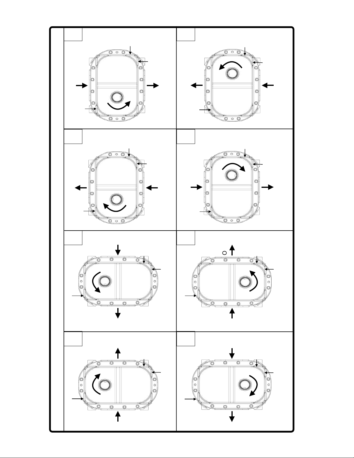
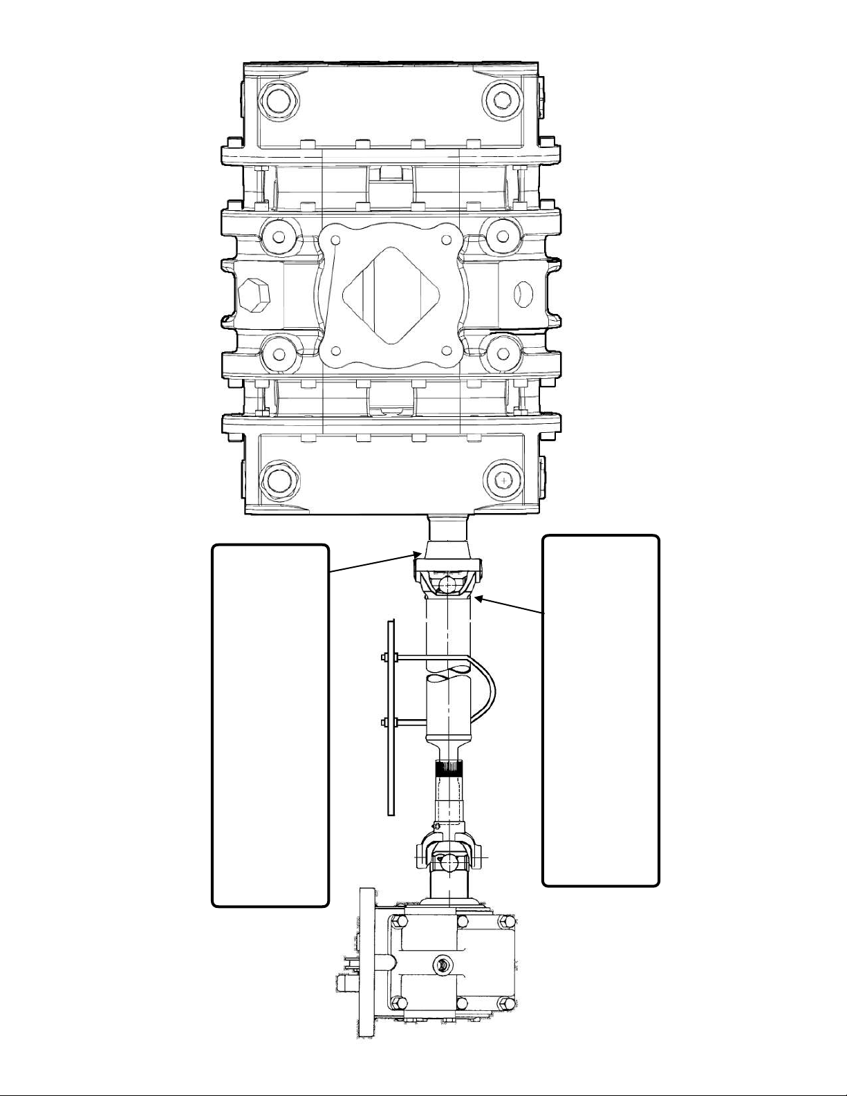
•In order to avoid becoming entangled, install the power take off and/or shaft behind the frame rail, tanks,
battery box, etc.
•If power take off and/or shaft are still exposed after installation, install a guard.
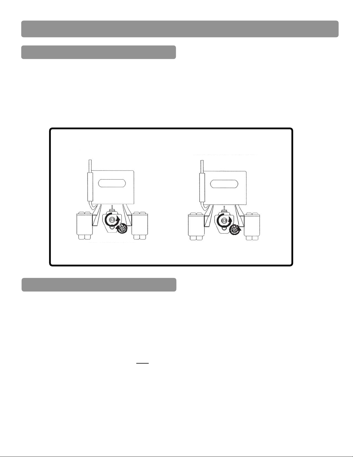
•Use provided drive shaft flange set screws and apply “Loctite® 243” or equivalent.
•Install a support strap when servicing a drive shaft to prevent personal injury.
A serious or fatal injury can occur. . .
-if you lack proper training.
-if you fail to follow proper precautions.
-if you do not use proper tools and safety equipment.
-if you assemble drive shaft components improperly.
-if you use incompatible drive shaft components.
-if you use worn-out or damaged drive shaft components.
-if you use drive shaft components in a non-approved application.
This manual contains safety instructions. Read, understand, and follow this manual.
•Get proper training.
•Learn and follow safe operating procedures.
•Use proper tools and safety equipment.
•Use proper components in good condition.
Safety Precautions

(800) 471-8769
2
Copyright 2021 © Paragon Tank Truck Equipment
Safety Notice

(800) 471-8769
3
Copyright 2021 © Paragon Tank Truck Equipment
Table of Contents
Section Page
Safety Precautions....................................................... 1
Safety Notice................................................................ 2
Blower Specifications................................................... 4
Mounting………………………………………………….. 5
Power Take Off………………………………….……….. 5
Blower Orientation……………………….……….. 5
Mounting Bracket Requirements……..…………. 7
Drive Shaft Installation……………………………. 7
Determine Blower Mounting Slope…..…………. 7
Suction Equipment………………..………………. 9
Delivery Discharge Pipework……………………. 9
ECM/TCM Programming…………….…………… 10
Blower Operation……………..…………….….………… 11
Lubrication Instructions................................................ 12
Preventative Maintenance............................................ 13
Safety Checklist…………….……………….…………… 14
Parts Listings…………………..…………………………. 15
Warranty Information.................................................... 21

(800) 471-8769
4
Copyright 2021 © Paragon Tank Truck Equipment
Airflow
Max Operating Pressure
Max Vacuum
RPM Range
Weight
221-604 CFM
18 PSI (20 PSI intermittent)
17 inHg
1000-2000 RPM
297
Note:
Reduce the maximum operating pressure by 1 PSI for each 2000 feet of altitude above sea level.
(Example: at an altitude of 4000 feet, the max operating pressure of the blower will decrease by 2 PSI)
PTO
Speed
RPM
Pressure
Vacuum
12 PSIG
16 PSIG
18 PSIG
20 PSIG
12 inHg
15 inHg
17 inHg
CFM
HP
CFM
HP
CFM
HP
CFM
HP
CFM
HP
CFM
HP
CFM
HP
1000
246
19
247
10
222
12
1100
282
21
265*
28
283
11
258
13
1200
318
23
301*
31
293*
34
319
12
294
14
1300
354
25
337
33
329
37
321*
41
355
14
330
17
310*
19
1400
390
27
372
36
365
40
357*
45
390
14
365
17
346*
19
1500
425
29
408
39
400
43
393*
48
426
14
401
18
328*
20
1600
461
31
444
41
436
46
429*
51
462
15
437
19
418*
22
1700
497
33
480
44
472
49
465*
55
498
16
473
20
453*
23
1800
533
35
516
47
508
52
500*
58
534
17
509
22
489*
24
1900
569
37
551
49
544
55
536*
61
569
18
544
23
525*
26
2000
604
40
587
52
579
58
572*
65
605
19
580
24
561*
27
*Intermittent operation only
(Fig. 1)
P657 Blower Specifications

(800) 471-8769
5
Copyright 2021 © Paragon Tank Truck Equipment
Blower Orientation (See Fig. 3-Page 6)
Power Take Off
•PTO Horsepower and torque rating must be adequate for desired blower RPM and pressure demand.
(See P657 Blower Specifications Fig.1, Page 4)
•Select proper ratio for the desired engine speed and correct blower input shaft speed.
(Engine RPM x PTO ratio = Blower RPM. Blower RPM 1000 min, 2000 max)
•Verify PTO rotation (See Fig.2).
•Determine the desired blower orientation prior to mounting.
Note:
Blower should be mounted on the same side of the truck as the PTO Location to keep drive shaft angles
to a minimum.
•Ensure sight glasses, melt plugs, magnetic plugs, and breathers are in the correct positions prior to mounting.
Note:
Melt plugs are left-hand threads. One plug must be on the discharge side of the blower.
•Sight glass should ALWAYS be on the lower side opening, closest to the frame rail.
•The magnetic drain plug should ALWAYS be installed pointing down.
•The breathers should ALWAYS be installed on the top of the oil tanks, shielded from elements.
Note:
Remote breather kits are available for harsh environments.
(Fig. 2)
Mounting the P657 Blower
Typical Eaton
Transmission
Crankshaft
Rotation
Clockwise PTO Rotation
Opposite: Opposite of the
crankshaft rotation
Typical DT-12
Transmission
Counter Clockwise PTO Rotation
Crank: Engine
crankshaft rotation
Crankshaft
Rotation

(800) 471-8769
6
Copyright 2021 © Paragon Tank Truck Equipment
All sight glasses, magnetic drain plugs, and breathers are shown for driver side installation; reverse sight glass locations for passenger side installation.
HA - Clockwise
HA - Counter Clockwise
VA - Clockwise
VA - Counter Clockwise
Sight !
Glass
Breather
Magnetic Drain
Plug
Out
In
Horizontal Airflow - HA
Vertical Airflow - VA
1
2
3
4
5
6
7
8
In
Sight !
Glass
Breather
Magnetic Drain
Plug
Out
Sight !
Glass
Breather
Magnetic Drain
Plug
Out
In
In
Sight !
Glass
Breather
Magnetic Drain
Plug
Out
In
Out
Magnetic Drain!
Plug
Sight !
Glass
Breather
Out
In
Magnetic Drain!
Plug
Sight !
Glass
Breather
In
Out
Magnetic Drain!
Plug
Sight !
Glass
Breather
In
Out
Magnetic Drain!
Plug
Sight !
Glass
Breather
(Fig. 3)

(800) 471-8769
7
Copyright 2021 © Paragon Tank Truck Equipment
Drive Shaft Installation
•The use of Paragon brackets is recommended.
•Should be strong enough to support the P657, accessories, and torque required.
•Must allow minimum of 3/4” clearance between the blower and frame rail to prevent damage to the
blower.
•Use Qty (4), 5/8” diameter bolts to mount the P657 Mounting Bracket to the tractor frame rail.
•Paragon strongly recommends consultation with a local drive shaft specialist PRIOR to drilling the tractor frame rail.
•At a minimum a drive shaft specialist should verify the following:
-Required length meets industry standards for safe operation at the desired rpm.
-Drive shaft is capable of operations for the required rpm.
-Equipment slopes are correct to minimize torsional vibrations.
-Confirm the drive shaft working angles are within industry specifications for safe operation(See Fig.4).
•A minimum 3” diameter DOM Tubing x 0.083 wall thickness be used for P657 Blower applications.
•That each drive shaft section has a “U” bolt hanger bracket for safety (See Fig.5, Page 8).
•A minimum Drive Shaft critical speed of 2000 rpm.
•Attach mounting bracket to the blower.
•Torque mounting bolts to the required torque (77 lbs·ft)
•Clamp the blower in place on the frame rail while
supporting the equipment from underneath.
•Contact a drive shaft specialist.
Drive shaft and other components may shift with changes in suspension.
Maximum Drive Shaft Working Angles
Speed Angle “A”
2000 RPM 8°
1800 RPM 9.5°
1500 RPM 11.5°
1000 RPM 13°
“A”
“A”
(Fig. 4)
Mounting Bracket Requirements
Determine Blower Mounting Slope
Caution

(800) 471-8769
8
Copyright 2021 © Paragon Tank Truck Equipment
(Fig. 5)
1310 Drive Flange -
1-5/8” w 3/8” key
Paragon Part Number:
560-044
(Included with Paragon Mounting Kits)!
1350 Drive Flange -
1-5/8” w 3/8” key
Paragon Part Number:
560-039
Drive Shaft to be field supplied.
(not provided by Paragon)
1310 Companion yoke
Industry part# 2-2-329
1350 Companion yoke
Industry part# 3-2-119

(800) 471-8769
9
Copyright 2021 © Paragon Tank Truck Equipment
•Ensure Discharge Flange is torqued to 30 lb/ft when installed.
•Ensure all delivery pipework is free from weld beads, foreign metal, and debris.
•Ensure all pipework components are capable of withstanding discharge temperatures and pressures.
•Ensure the Pressure Relief Valve is mounted as close as possible to the blower discharge.
Note:
Pressure Relief Valves need to be checked weekly and replaced periodically; these must be placed in a
serviceable location.
•If a Silencer or Check Valve is installed, ensure it is sized for the proper CFM range.
•Ensure these are mounted downstream of the Pressure Relief Valves.
Note:
Check Valves will protect the equipment from back flow of product. These must be inspected and replaced periodically.
•Ensure a Vacuum Relief Valve is used if any equipment will be used for vacuum duty of any kind.
-Ensure Vacuum Relief Valve is sized for the correct CFM.
-Ensure Vacuum Relief Valve rating does not exceed 15 inHg.
-A Vacuum Relief Valve should be positioned between the filter outlet and P657 Inlet Flange.
Suction (Inlet) Equipment
•Ensure the Inlet flange is torqued to 30 lb/ft.
•Ensure the Air Filter is sized for the correct airflow (CFMs) operating range of the blower.
•Ensure the Air Filter is mounted as far from any heat sources as possible.
An undersized filter will cause damage to the equipment (overheating)
Caution
Caution
The filter should not exceed 17 inches of water restriction.
•Inlet Pipework should be free of weld beads, foreign metal, and debris before installing.
•For vacuum applications all rubber elbows must have reinforcement to prevent collapsing during normal operations.
Caution
If operating under vacuum a Vacuum Relief Valve should be installed.
Delivery Discharge Pipework

(800) 471-8769
10
Copyright 2021 © Paragon Tank Truck Equipment
•Paragon recommends that a factory dealer/technician program your tractor for optimal ECM/TCM performance.
•Ensure the engine range RPM is programmed within the operational limits of the P657 Blower.
•Ensure the engine RPM ramp up rate, after PTO engagement, is set for no more than 100 rpm per second.
•Ensure the torque output settings are correct for the equipment operation parameters.
Note:
For more available options regarding ECM/TCM programming, please contact your local chassis dealer.
•Engine is off and keys are not in the ignition.
•Ensure all connections are supported.
•Ensure the Camlock (discharge) connection is venting to atmosphere.
•Ensure the air filter is properly installed and free of contaminates.
•Ensure the P657 can be turned by hand.
•Ensure all equipment supplied labels are installed.
•Ensure all fasteners are installed and torqued properly.
•Ensure ECM parameters are properly set (if applicable).
•Ensure oil level is correct (see page 12 for details).
ECM/TCM Programming
Pre-Start Up

(800) 471-8769
11
Copyright 2021 © Paragon Tank Truck Equipment
•Inspect blower mounting, drive shaft, P.T.O. and air filter for integrity.
•Remove camlock dust cap and connect the hot air hose.
•Follow trailer manufacturer’s recommendation regarding hose connections and proper valve operation.
•Slowly engage P.T.O. with engine at idle as per PTO manufacturer’s recommendations.
•Bring engine RPM up to operating speed and engage preprogrammed RPM.
•Unload trailer as per trailer manufacturer’s recommendation.
•While discharging, visually check blower for vibration, mechanical noise, or excessive heat.
•If blower relief valve or melt plug is activated, reduce the line pressure to 0 psi.
-Shut down the P657 by disengaging the PTO, shut off the engine, and check for blockages
•Disengage P.T.O. according to manufacturer’s instructions, shut off engine.
•Disconnect blower hose and replace camlock dust cap.
Caution
The blower and accessories will become hot enough to cause skin burns on contact.
Rotating machinery is dangerous.
Warning
Always wear ear protection when in close proximity to blower.
Warning
Blower Operation

(800) 471-8769
12
Copyright 2021 © Paragon Tank Truck Equipment
Oil Capacity
Horizontal Air Flow (Standard Mount)
Vertical Air Flow
Drive End (Front Cover)
Non-Drive End (Rear Cover)
15 oz (0.5 qt.)
25 oz (0.8 qt.)
28 oz. (0.9 qt.)
48 oz. (1.5 qt.)
Max Oil
Fill Level
Max Oil
Fill Level
(Fig. 6)
Lubrication Instructions
•Use Paragon Lobe Blower Oil (part number: 409-007).
Caution
Mixing or incorrect oil can result in gear and bearing failure.
Note:
Front oil tank will fill slower than the rear tank. Allow oil to settle after it begins to show in the sight glass.
Correct Level
Over filled
Under Filled
Sight Glass
Filling
Instructions

(800) 471-8769
13
Copyright 2021 © Paragon Tank Truck Equipment
•A proper maintenance program will keep your P657 blower in top running condition. A newly installed P657 blower
should be checked frequently during the first month of operation. Use only Paragon Blower Oil. Check oil levels and
add as needed.
•An oil analysis program is recommended.
-In the absence of an oil analysis program, change oil in both tanks every 500 hours.
Note:
Correct Oil Level is 1/2 to 7/8 full on the sight glass (See Fig. 6-Page 12). Air bubble must be visible at the top
of sight glass.
Daily
1.Check and maintain oil levels, add oil as necessary.
2.Check Air Filter restriction indicator.
Weekly
1.Check and maintain oil levels, add oil as necessary.
2.Check Air Filter restriction indicator.
Monthly
1.Inspect the entire system for leaks.!
2.Inspect condition of oil and change if necessary.
Semi-Annually
1.Inspect the PTO components.!
2.Use an oil analysis program.
Preventative Maintenance

(800) 471-8769
14
Copyright 2021 © Paragon Tank Truck Equipment
Complete prior to blower operation
Truck #_________________________
Transmission#___________________
P.T.O.#_________________________
P.T.O. Ratio _____________________
Read and understand Installation Manual.
The following have been verified before installing the PTO:
PTO model # matches packaged model #.
PTO mounting flange is correct for desired P657 mounting location.
PTO ratio has been verified.
PTO torque capabilities are acceptable for blower operation.
PTO rotation is correct for desired P657 orientation.
PTO is mounted per manufacturer’s recommendation.
Transmission has been filled to the proper oil level as required by the manufacturer.
The Blower can be rotated by hand without lobes touching or clashing.
Drive shaft is installed correctly.
Provided drive shaft flange set screws have been installed with “Loctite® 243” or equivalent.
Air Inlet is installed as far away from heat sources as possible.
All bolt torques have been verified.
All supplied warning labels have been installed.
The correct Relief Valve has been installed properly.
Melt Plug is installed on the discharge side of the blower.
Sight glasses and magnetic drain plug can be seen to identify oil level in P657 oil tanks after
installation.
Breathers are installed in the proper location.
P657 front and rear oil tanks are filled to the proper levels (1/2 to 7/8 full).
Blower model # P657 Blower
Blower serial # __________________
Date__________________________
Inspected by____________________
Safety Checklist

(800) 471-8769
15
Copyright 2021 © Paragon Tank Truck Equipment

(800) 471-8769
16
Copyright 2021 © Paragon Tank Truck Equipment
P657 Blower Spare Parts
Item
Part#
Description
Qty
1
503-005
P657 Shaft Drive
1
2
571-023
Spacer
1
3
555-007
Oil Seal, Shaft
1
4
296-021
Washer, Rotor
2
5
128-008
Capscrew
16
6
141-001
Plug, Magnetic
2
7
529-004
Step Up Gear Set
1
8
555-008
Tank/Sideplate Oil Seal
4
9
523-037
Blower DE Cover
1
10
297-003
Ring, Internal Snap Retaining Lab Seal
4
11
556-038
Labyrinth Seal
4
12
274-002
Dowel Pin
6
13
543-003
Melt Plug
2
14
502-007
Blower Driven Rotor
1
15
500-035
Body
1
16
224-006
Capscrew
32
17
501-010
Sideplate, Blower NDE
1
18
582-018
Bearing Retainer
4
19
323-005
Hyd. Plug
10
20
582-020
Retainer - Inner Lock Ring
4
21
582-019
Retainer Bushing
2
22
529-003
Timing Gear Set
1
23
124-027
Capscrew
10
24
510-006
Double Row Bearing
2
25
523-036
Blower NDE Cover
1
26
228-030
Capscrew
8
27
571-022
Drive Gear Spacer
1
28
582-022
Spiral Ring Retainer
2
29
502-006
Blower Drive Rotor
1
30
510-007
Bearing, Double Row, Step Up
1
31
512-003
Bearing, Rolling
2
32
501-011
Blower DE Sideplate
1
33
224-014
Capscrew
24
34
527-030
Oil Deflector
4
35
571-021
Bearing Spacer
3
36
527-025
Slinger, Blower
1
37
124-008
Socket Capscrew
2
38
512-004
Roller Bearing
1
39
558-002
Seal, Gamma Rotary w/ Labyrinth P657 Drive Shaft
1
40
198-000
Key, Parallel Small Gear (Not Shown)
1
41
174-004
Spring Pin (Not Shown)
1
42
192-000
Rivet (Not Shown)
4
43
See 543-003
Blank Plug - Lefthand (Not Shown)
2
44
355-008
Hyd Sight Glass (Not Shown)
2
45
409-007
Oil, Quart (Not Shown)
3
46
526-037
Bonded Sealing Washer(Not Shown)
16
47
613-001
Hyd Breather Assembly
2

(800) 471-8769
17
Copyright 2021 © Paragon Tank Truck Equipment
P657 Air Filter Assembly - Spare Parts
Item
P/N
Description
Qty
A
576-009
Cap Assembly
1
B
576-012
Rubber Flex Latch
2
C
576-010
Head Assembly- P657/CDL9/CDL12/ Latches
1
D
612-043
Kit, Bracket (set of 2) -S/S Air Filter Mounting
1
E
575-005
Filter Element - CDL9/CDL12/P657 *For Filter Assembly
625-003
1
F
576-007
Body-CDL9/CDL12/ P657
1
G
533-045
Camlock 4” Male
1
H
576-008
Clamp Assembly ⅜” *Includes Wingnut (Item O)
1
I
284-019
Wing Nut, filter element - P657/CDL9/CDL12 (Not Shown)
1
J
526-000
Gasket
1
O
184-004
SS hex body for Filter Band Clamp
1
Item
P/N
Description
Qty
A
576-009
Cap Assembly (PSI/VAC)
1
B
576-012
Rubber Flex Latch
2
C
576-010
Head Assembly - P657/Latches
1
D
612-043
Kit, Bracket (set of 2) - S/S Air Filter Mounting
1
G
533-045
Camlock 4” male
1
H
576-008
Clamp Assembly ⅜”
*Includes Wingnut (Item O)
1
J
526-000
Gasket
1
K
575-007
Filter Sock for 573-003 Element
*Installs on the inside of the filter element
1
L
576-013
Cap Assembly (PSI only)
1
M
573-003
Filter Element - P657
*For Filter Assembly 625-006 & 625-002
1
N
576-006
Body - P657 Side Outlet
1
576-018
Body - P657 Side Outlet w/ Gauge
( PSI/VAC only )
1
O
184-004
SS hex body for Filter Band Clamp
1

(800) 471-8769
18
Copyright 2021 © Paragon Tank Truck Equipment
#
P/N
Description
Qty
1
601-014
P657 Blower
1
2
508-109
VA Bracket
1
3
508-110
VA Blower Mounting Strap
2
4
560-044
P657 Drive Flange 1310 Series
1
5
228-093
P657 Blower Mount Bolts
4
6
296-014
Flat Washer
6
7
294-011
Lock Washer
6
8
284-015
Hex Nut
2
9
228-052
Capscrew
4
10
296-022
Flat Washer
4
11
294-009
Lock Washer
4
12
284-009
Nyloc Hex nut
4
13
625-003
Filter Assy S/S PSI/VAC 4” Bottom Outlet
1
14
587-018
Hose, Hump - 4”
1
15
526-036
Gasket, Delivery, Suction - P657
1
16
509-034
Flange, Suction Alum, P657
1
17
224-023
Capscrew- Socket Head
4
#
P/N
Description
Qty
18
296-012
Flat Washer
4
19
291-002
Hose Clamp, Worm
2
20
563-002
Muffler, 4” TTMA X 4” FNPT - Steel
1
21
533-005
Elbow, 2” Street - Galvanized
1
22
610-012
Relief Valve, 2” NMPT - 16 psi
1
22
610-013
Relief Valve, 2” NMPT - 18 psi
1
23
509-033
Flange, Discharge Cast Iron P657 VA
1
24
526-036
Gasket, Delivery, Suction - P657
1
25
526-011
Gasket, 4” TTMA
1
26
567-002
Camlock 3” Maie X 4” MNPT - Alum
1
26
533-045
Camlock 4” Male X 4” MNPT - Alum
1
27
565-001
Camlock Dust Cap 3” - Alum
1
27
565-002
Camlock Dust Cap 4” - Alum
1
28
224-023
Capscrew- Socket Head
4
29
296-011
Flat Washer
4
30
228-105
Capscrew - Hex Head
8
31
284-008
Hex Nut
8
32
296-008
Flat Washer
8

(800) 471-8769
19
Copyright 2021 © Paragon Tank Truck Equipment
#
P/N
Description
Qty
1
601-012
P657 Blower, with 3 Qts of Oil
1
2
508-107
HA Blower Bracket - P657 (Straight)
1
2
508-113
HA Blower Bracket - P657 Drivers Side
1
2
508-114
HA Blower Bracket - P657 Pass. Side
1
3
560-044
P657 Drive Flange 1310 Series (not shown)
1
4
625-006
Air Filter Assy S/S - P657 PSI Only 5” Side
outlet
1
4
625-002
Air Filter Assy S/S - P657 PSI/Vac 5” Side outlet
1
4
625-026
Air Filter Assy S/S - P657 PSI/Vac 5” Side outle,
with Vaccuum Gauge
1
5
587-000
Hose, Hump 5” X 4”
1
6
588-010
Tube, 4” od X 24” long
1
7
587-018
Hose, Hump 4”
1
8
526-036
Gasket, Delivery, Suction - P657
1
9
509-032
Flange, Suction Alum - P657 HA
1
10
291-012
Hose Clamp 4” - 6”
1
#
P/N
Description
Qty
11
291-002
Hose Clamp 3” - 5”
3
12
228-052
Capscrew - Hex Head
4
13
296-022
Flat Washer
4
14
294-009
Lock Washer
4
15
284-009
Nyloc Hex Nut
4
16
623-022
Air Filter Mounting Kit
1
17
563-000
Muffler, 4” MNPT X 4” FNPTSteel
1
17
563-007
Muffler, 4” MNPT X 4” FNPT Steel w Temp.
Gauge (not for food grade or sensitive
products)
1
17
563-001
Muffler, 4” MNPT X 4” FNPT Stainless Steel
1
17
563-002
Muffler, 4” MNPT X 4” FNPT Stainless Steel w
Temp. Gauge
1
18
533-005
Elbow, 2” Street - Galvanized
1
19
610-012
Relief Valve, 2” NMPT - 16 psi
1
19
610-013
Relief Valve, 2” NMPT - 18 psi
1
Horizontal Airflow (HA)
Diagram
Table of contents
Other Paragon Blower manuals