Paragon P858 User manual

Installation
and
Operation
Manual
Truck Blower
P858 & P1057 Operation Manual
Version: 02-17-2022

(800) 471-8769
1
Copyright 2022 © Paragon Tank Truck Equipment
Table of Contents
Section Page
Safety Notice................................................................ 1
Safety Precautions & Safety Check List....................... 2
Melt Plug Information…………………………………… 3
Blower Specifications................................................... 4
Mounting………………………………………………….. 5-7
Power Take Off………………………………….… 5
Mounting Bracket Requirements……..…………. 5
Determine Blower Mounting Slope…..…………. 5
Suction Equipment………………..………………. 5
Delivery Discharge Pipework……………………. 5
Drive Shaft Installation……………………………. 5-6
Blower Orientation……………………….……….. 7
Preventative Maintenance............................................ 8
Lubrication Instructions................................................ 8
Blower Operation……………..…………….….………… 8
Parts Listings…………………..…………………………. 9-14
Warranty Information.................................................... 15
Safety Notice

(800) 471-8769
2
Copyright 2022 © Paragon Tank Truck Equipment
Safety Precautions
•Rotating shafts can be dangerous. You can snag
clothes, skin, hair, and hands. This can cause serious
injury or death.
•Do not work under the vehicle when the engine is
running.
•Do not work on a shaft (with or without guard) when
the engine is running.
•If the power take off and/or shaft are still exposed after
installation, install a guard.
•Install a support strap when servicing a drive shaft to
prevent personal injury.
•A serious or fatal injury can occur....
-If you lack proper training.
-if you fail to follow proper procedures.
-if you do not use proper tools and safety
equipment.
-if you assemble driveline components improperly.
-if you use incompatible driveline components.
-if you use worn-out or damaged driveline
components.
-if you use driveline components in a non-approved
application.
•This manual contains safety instructions.
Read, understand and follow this manual.
-Get proper training.
-Learn and follow safe operating procedures.
-Use proper tools and safety equipment.
-Use proper components in good condition.
Safety Check List
Complete prior to blower operation
Truck # ____________________________
Transmission # ____________________________
PTO # ____________________________
PTO Ratio ____________________________
Blower model # ____________________________
Blower serial # ____________________________
Date ____________________________
Inspected by ____________________________
☐Is PTO ratio, torque and rotation correct?
☐Mount PTO as per manufacturer’s recommendations and
refill transmission.
☐Ensure oil level is at the center of the sight glasses.
☐Driveline installed correctly and blower can be rotated by
hand.
☐Air inlet filter is connected and mounted away from tractor
exhaust.
☐Remove camlock dust cap, discharge pipework open to
atmosphere.
☐Tractor engine at idle. Slowly engage PTO Check for
correct rotation and airflow.
☐Slowly take blower up to operating speed.
☐Check for vibration, mechanical noise, oil leaks and
mounting integrity.
☐Stop blower. Connect blower discharge hose to trailer and
run blower at operating pressure of trailer (15 psi) for 15
minutes at normal speed.
☐Does relief valve allow 15 psi tank pressure?
☐Does engine maintain correct rpm throughout the test?
☐Turn off truck engine, wait for blower to stop turning.
Check fusible plugs, relief valve, filter, pipework and oil
sumps for integrity.
☐Is correct engine speed label visible in cab?
☐Install driveline warning labels to both sides of the frame.

(800) 471-8769
3
Copyright 2022 © Paragon Tank Truck Equipment
Melt Plug Information
The fast acting melt plug is designed to reduce the blower operating pressure and
temperature when the machine is operated beyond its limits.*
There are two plugs located near the blower flanges. When the blower is operated
beyond its operating range, the following will happen:
Loosen
Left Hand Thread
•The temperature increases.
•The solder (Figure 1, Reference # 1) melts.
•The thin disc (Figure 1, Reference # 2) is released.
•Pressure drops 4-6 psi at 1800 RPM.
•Audible sound from the plug alerts the driver of a problem.
•Operator should shut down blower and try to locate the problem.
•When the problem is corrected, operator can fit a new plug (left hand
thread) or use the plug from the suction side of the machine.
Note: Replace blown melt plugs immediately to prevent further damage to the
blower. Do not re-install blown melt plugs.
Fig. 1
Caution:
If problem cannot be corrected, do not increase blower speed as this can cause
further damage to the blower. This overheating condition should be reported to
the maintenance department immediately.
*Vacuum applications require a vacuum valve for blower protection.
Caution:
Do NOT operate blower after a melt plug has blown.

(800) 471-8769
4
Copyright 2020 © Paragon Tank Truck Equipment
Airflow
CFM
Max.
Pressure
Max.
Vacuum
Speed Range
Weight
P858
390-1000
at 2 PSI
20 PSI
(See Note 1)
17” of Hg
1800-3000 RPM
(See Note 2)
366 lbs
Note:
1) Reduce the maximum operating pressure by 1 psi for every 2000 feet of altitude above seal level.
(Example: at an altitude of 4000 feet, the maximum working pressure of the blower will decrease by 2 psi)
2) Check PTO manufacturer’s max RPM.
Front
12.13”
18.06”
Melt Plug (2 places)
Left Hand Thread
Bottom Shaft Shown
1-5/8” Round with 3/8” key
M16
Mounting
Holes (4)
M12
Flange
Holes (4)
2.63”
Side
22.25”
Top Shaft
Blank Cap
P858 Blower Specifications
Performance Chart for Power Take-Off Operation
(See
Note
2)
Blower
Speed RPM
Pressure Performance and Horsepower
Vacuum Performance and Horsepower
12 PSIG
16 PSIG
18 PSIG
20 PSIG
12” of Hg.
16” of Hg.
17” of Hg.
CFM
BHP
CFM
BHP
CFM
BHP
CFM
BHP
CFM
BHP
CFM
BHP
CFM
BHP
1800
479
33
462
42
447
50
437
55
493
17
464
21
440
23.29
1900
514
35
497
44
482
52
472
58
528
18
498
22
475
24.59
2000
549
37
532
46
516
55
507
61
563
18
533
23
510
25.88
2100
584
39
566
49
551
58
541
64
597
19
568
24
545
27.17
2200
618
41
601
51
586
61
576
68
632
20
602
25
579
28.47
2300
653
43
636
53
620
64
611
71
667
21
637
26
614
29.76
2400
688
45
671
56
655
66
645
74
701
22
672
27
649
31.05
2500
722
47
705
58
690
69
680
77
736
23
707
29
683
32.35
2600
757
48
740
60
724
72
715
80
771
24
741
30
718
33.64
2700
792
50
775
63
759
75
750
83
806
25
776
31
753
34.94
2800
826
52
809
65
794
78
784
86
840
26
811
32
787
36.23
2900
861
54
844
67
829
81
819
89
875
27
845
33
822
37.52
3000
896
56
879
70
863
83
854
92
910
28
880
34
857
38.82

(800) 471-8769
5
Copyright 2020 © Paragon Tank Truck Equipment
Airflow
CFM
Max.
Pressure
Max.
Vacuum
Speed Range
Weight
P1057
535-1340
at 2 PSI
19 PSI
(See Note 1)
17” of Hg
1700-3000 RPM
(See Note 2)
419 lbs
Note:
1) Reduce the maximum operating pressure by 1 psi for every 2000 feet of altitude above sea level.
(Example: at an altitude of 4000 feet, the maximum working pressure of the blower will decrease by 2 psi)
2) Check PTO manufacturer’s max RPM.
Blower
Speed RPM
Pressure Performance and Horsepower
Vacuum Performance and Horsepower
12 PSIG
16 PSIG
18 PSIG
19 PSIG
12” of Hg.
16” of Hg.
17” of Hg.
CFM
BHP
CFM
BHP
CFM
BHP
CFM
BHP
CFM
BHP
CFM
BHP
CFM
BHP
1700
587
42
556
55
543
62
536
66
605
22
565
27
534
31
1800
633
44
602
59
589
66
582
69
651
22
611
27
580
31
1900
679
47
648
62
635
70
628
73
697
23
657
29
626
32
2000
725
49
694
65
681
73
674
77
743
24
703
30
572
35
2100
771
52
740
69
727
77
720
81
789
25
749
32
718
36
2200
817
54
786
72
773
81
766
85
835
27
795
33
764
38
2300
863
57
832
75
819
84
812
89
881
28
841
35
810
39
2400
909
59
878
79
865
88
858
93
927
29
887
36
856
41
2500
955
61
924
82
911
92
904
97
973
30
933
38
902
43
2600
1001
65
970
85
957
96
950
101
1019
32
979
39
948
44
2700
1047
67
1016
89
1003
100
996
105
1065
33
1025
41
994
46
2800
1093
70
1062
92
1049
103
1042
109
1111
34
1071
42
1040
48
2900
1139
72
1108
96
1095
107
1088
113
1157
35
1117
44
1086
50
3000
1185
75
1154
99
1141
111
1134
117
1203
36
1163
45
1132
51
Front
12.13”
18.06”
Melt Plug (2 places)
Left Hand Thread
Bottom Shaft Shown
1-5/8” Round with 3/8” key
M16
Mounting
Holes (4)
M12
Flange
Holes (4)
2.63”
Side
24.38”
Top Shaft
Blank Cap
P1057 Blower Specifications
Performance Chart for Power Take-Off Operation
(See
Note
2)

(800) 471-8769
6
Copyright 2020 © Paragon Tank Truck Equipment
These angles will be equal
( Viewed from below )
Caution:
Incorrect equipment will cause blower failure. If you are not using
a Paragon kit, the following accessories should be installed:
Power Take Off For Transmission
•Horsepower and torque rating must be adequate for blower
RPM and pressure.
•Select ratio for required engine speed and correct blower
shaft speed.
Constant Engine Speed
•The selected engine speed must remain constant throughout
the blower discharge cycle. This requires ECM programming
or a trouble control system.
•Program ECM for max 100 RPM “ramp rate” per second.
Relief Valve
•Sized for correct CFM and blower pressure rating.
•Installed on delivery side before check valve.
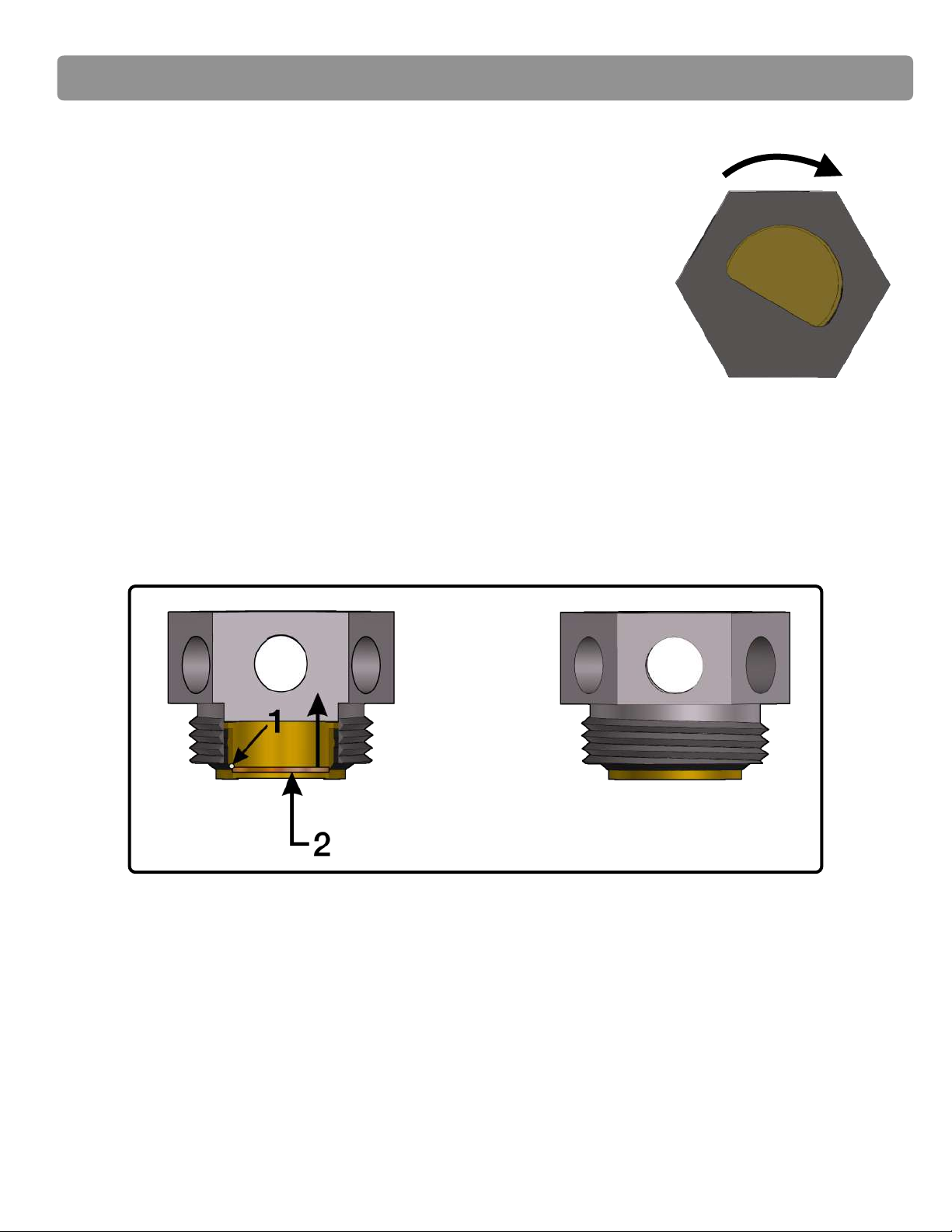
•Use pipe compound on male pipe thread of relief valve.
•DO NOT use thread tape.
Air Filter
•Sized for correct CFM to suit application.
Caution: An undersized filter will cause immediate
overheating of blower. The filter should not exceed 17” water
restriction. Do not mount air inlet of the filter close to truck
exhaust. This will increase the blower operating temperatures
above the maximum limits.
Suction Delivery and Pipework
•Should be free of weld beads and foreign metal.
•During vacuum applications, NEVER use rubber elbows
without internal support. Rubber elbows will collapse
under vacuum, restricting the airflow to the P858/P1057,
and causing the P858/P1057 to overheat.
Mounting Bracket
•Strong enough to support blower weight and torque
•Allow a minimum of 1/2" clearance between the blower and
frame rail (or other non-moveable object) to prevent damage
to the blower.
Check Valve
•Sized for maximum CFM with minimal restriction.
•Should have at least (1) check valve mounted on the trailer at
the hot air hose connection.
•Must be inspected periodically for damage.
Mufflers
•Sized for maximum CFM with minimal restriction.
•Mounted downstream of the relief valve.
•Stainless steel is required for sensitive product applications
Vacuum Relief Valve (Tractor Mounted)
•Sized for correct CFM ( Not to exceed 15” of Hg ).
•This valve needs to be installed between the P858/P1057
Blower filter and the P858/P1057 inlet.
•Must be fitted with a separate filter element to prevent Blower
damage when it opens.
Note: When vacuum loading it is important that a vacuum relief
valve is installed within the system.
Maximum Driveline Working Angle
Speed
Angle “A”
3000 RPM
5 degrees
2500 RPM
7 degrees
2000 RPM
8 degrees
1800 RPM
9.5 degrees
•Blower shaft to be parallel with first shaft to within 1
degree.
Mounting Plane
•Blower can mount in two planes for horizontal and
vertical airflow.
Note:
1. Pre-cleaners are not recommended.
2. Use only packing-free stainless steel mufflers
for contamination sensitive products.
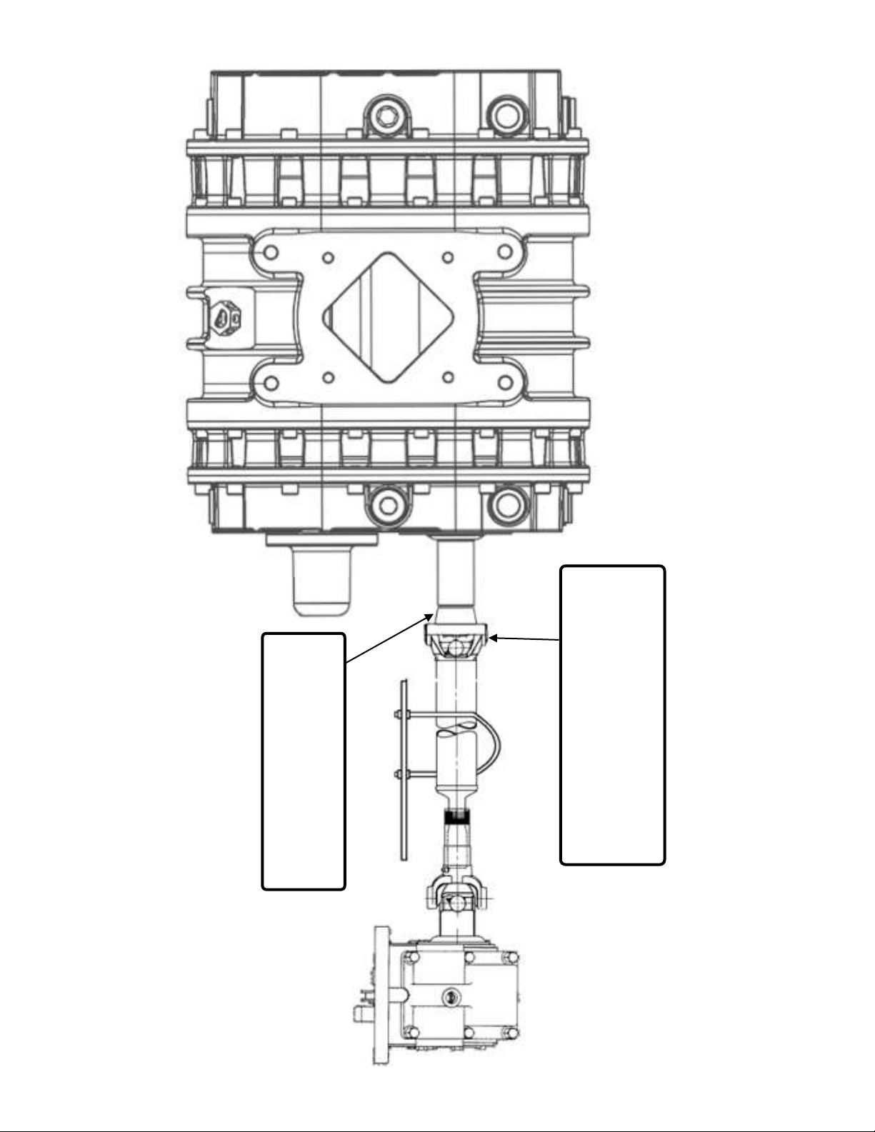
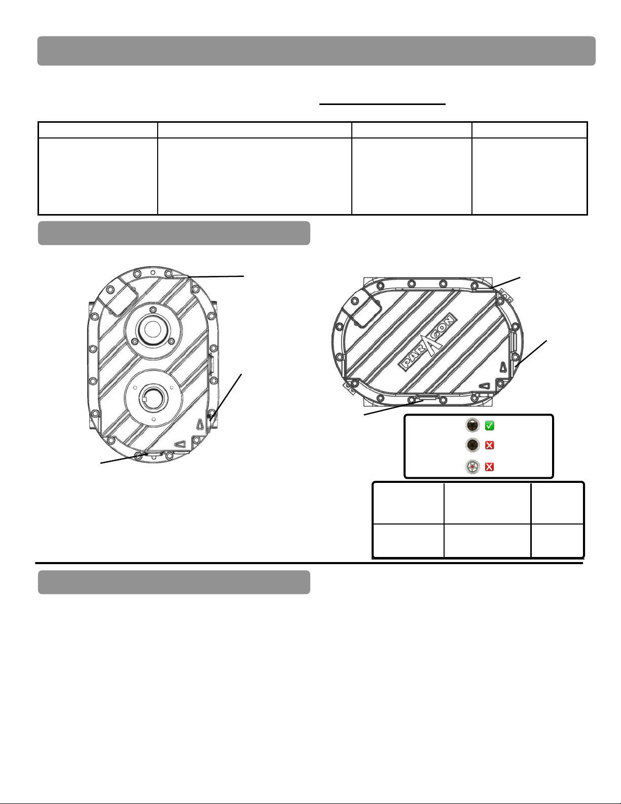
PTO Drive Shaft Single Piece
•Blower shaft must be parallel with the PTO
shaft axis within +/- 1 degree to minimize
vibration.
•Use tubular, balanced drive shaft.
•Do not force end yokes into Blower or PTO
shaft.
•Blower shaft is 1-5/8” dia. with 3/8” key.
•Maximum driveline working angle - see table
below:
PTO Drive Shaft Two Piece
•Consult local driveline specialist prior to operation
Must be Parallel to Frame
( No horizontal slope allowed )
These angles will be equal
Adjust to match slope
Min. Joint Angle
1-1/2°
Typical P858/P1057 Horizontal Installation
( Side View )
Aº
Aº
Mounting the P858 & P1057 Blower

(800) 471-8769
7
Copyright 2020 © Paragon Tank Truck Equipment
1310 Drive Flange - 1-5/8” w 3/8” key
Part Number: 560-044.
Drive Shaft to be field supplied. Companion
yoke - reference industry part number
2-2-329
(not provided by Paragon).

(800) 471-8769
8
Copyright 2020 © Paragon Tank Truck Equipment
HA - Driver Side
Horizontal Airflow - HA
1
2
3
4
HA - Passenger Side
In
Out
Magnetic Drain!
Plug
Sight !
Glass
Breather
In
Out
Magnetic Drain!
Plug
Sight !
Glass
Breather
Out
In
Magnetic Drain!
Plug
Sight !
Glass
Breather
Out
In
Magnetic Drain!
Plug
Sight !
Glass
Breather
Vertical Airflow - VA
1
2
VA - Driver Side
VA - Passenger Side
Sight !
Glass
Breather
Magnetic Drain
Plug
In
Out
Sight !
Glass
Breather
Magnetic Drain
Plug
In
Out
NOTE: Sight glasses and magnetic drain plugs will need to be re-positioned prior to installation and/or filling with oil.
All models are shipped in the “2” Orientation.

(800) 471-8769
9
Copyright 2020 © Paragon Tank Truck Equipment
Oil Capacity
Horizontal Airflow
(Standard Mount)
Vertical
Airflow
Drive End
Non-Drive End
28.32 oz.
38.57 oz.
35.18 oz.
46.73 oz.
Preventative Maintenance
• Inspect blower mounting, driveline, PTO and air filter for integrity.
•Verify melt plugs are intact - replace as needed prior to operation.
• Remove camlock dust cap and connect the hot air hose.
• Follow trailer manufacturers recommendation regarding product hose connection and valve operation.
• Slowly engage PTO with engine at idle.
• Bring up to operating speed and lock engine at recommended speed (shown in cab).
• Unload trailer as per trailer manufacturer’s recommendation and do not exceed maximum tank pressure.
• While discharging, visually check blower for vibration, mechanical noise or excessive heat.
• If relief valve is operating adjust proportioning valve to reduce tank pressure.
• Reduce pressure to zero as per trailer manufacturers instructions.
• Disengage PTO (No cool down period required).
• Disconnect blower hose and replace camlock dust cap.
Caution:
- The blower and accessories will become hot enough to cause serious skin burns on contact.
- Rotating machinery is dangerous.
- Always wear ear protection when in close proximity to blower.
Horizontal
Airflow
Filler Plug
Sight Glass
(5/8 Full)
Magnetic
Drain Plug
Filler Plug
Sight Glass
(5/8 full)
Magnetic
Drain Plug
Standard Oil: P858/P1057 oil (Paragon part number: 409-002)
Caution: Mixing or incorrect oil can result in gear and
bearing failure.
Daily
Weekly
Monthly
Semi-Annually
1.Check and maintain oil
level, add oil as
necessary.
1.Clean Air Filter. Clogged air filters can
seriously affect the efficiency of the blower.
1.Inspect the entire
system for leaks.
1.Inspect the driveline
components.
1.Check Air Filter element.
2.Check Relief Valve to assure it is operating
properly.
2.Inspect condition of oil
and change if necessary.
2.Change oil (even if 500
operating hours has not
been reached).
A good maintenance program will keep your P858/P1057 blower in top running condition. A newly installed P858/
P1057 blower should be checked frequently during the first month of operation, especially lubrication. Check oil levels
and add as needed. Complete oil changes are recommended every 500 operating hours, or more frequently (An oil
analysis program is recommended). Below is Paragon’s recommended minimum maintenance program.
Blower Operation
Lubrication Instructions
Correct Level
Over filled
Under Filled
Sight Glass
Filling
Instructions
Vertical
Airflow

(800) 471-8769
10
Copyright 2020 © Paragon Tank Truck Equipment
Vertical Airflow (VA)
Diagram
#
P/N
Description
QTY
1
625-006
Filter, Assy S/S Side Outlet P858/P1057
psi only
1
2
625-002
Filter, Assy S/S Side Outlet P858/P1057,
psi/vac
1
3
508-029
Bracket- Mounting no holes- P1057 VA
1
4
508-021
Angle Strap
2
5
533-005
2” Street Elbow
1
6
610-012
Relief Valve 16 psi
1
6
610-013
Relief Valve 18 psi
1
7
565-001
Dustcap 3”
1
7
565-002
Dustcap 4”
1
8
567-002
Camlock 3” male x 4” NPTM
1
8
533-045
Camlock 4” male x 4” NPTM
1
9
563-002
Muffler, 4” TTMA x 4” FNPT - steel
1
10
228-105
3/8” Bolt 1-1/2” long
2
11
294-009
3/8” Washer
2
12
284-008
3/8” Nut GR5 plated
2
10
228-066
7/16” Bolt TTMA Flange
6
11
296-011
1/2” Washer Plain Flat (for TTMA Flange)
6
12
284-007
7/16” Nut TTMA Flange
6
13
526-011
TTMA Gasket
1
14
509-010
Discharge Flange
1
15
526-002
Flange Gasket
1
16
128-025
M12 x 30 Bolt- Discharge Flange
4
17
196-008
M12 Washer- Discharge Flange
4
18
128-037
Cap Screw M16 x 35mm
4
19
194-007
M16 Lock Washer
4
20
228-095
5/8” Cap Screw Angle Strap
2
21
294-011
5/8” Lock Washer Angle Strap
2
22
296-014
5/8” Flat Washer Angle Strap
2
23
284-015
5/8” Nut Angle Strap
2
24
601-017
P858 Blower
1
24
601-016
P1057 Blower
1
25
526-002
Flange Gasket
1
26
124-020
Cap Screw M12 x 25mm
2
27
509-005
Suction Flange
1
28
124-023
Cap Screw M12 x 85mm
2
29
291-012
4”-6” Hose Clamp
2
30
587-002
Hump hose- 5”
1
31
625-003
Filter Assy S/S Bottom Outlet P858/P1057,
PSI/VAC
1
32
587-000
Hump Hose Reducer- 4” x 5”
1
33
588-003
Tube, Aluminum 5” x 5” long
1
34
587-005
Hose, 3-1/2” long x 5” ID-EPDM
1
29b
291-012
4”-6” Hose Clamp
4
Vertical Airflow Pressure/Vacuum Filter
Connection
Note: Bottom Outlet Filter
is always recommended
for Vertical Airflow.
10
11
12
13
14
15
16
17
18
19
20
21
22
23
24
25
26
4 5 6 7 8 9
1 or 2
3
31 32 33 34 29b
30 29 28 27

(800) 471-8769
11
Copyright 2020 © Paragon Tank Truck Equipment
#
P/N
Description
QTY
30
587-002
Hump hose- 5”
2
36
563-000
Muffler, 4” MNPT x 4” FNPT - steel
1
36
563-001
Muffler, 4” MNPT x 4” FNPT - S/S
1
37
128-025
Capscrew 8.8 M12 x 30mm
4
38
196-008
Flat Washer, M12
4
39
509-001
Flange, Delivery CI, H/A
1
40
508-061
Mounting Bracket - Passenger Side
1
40
508-025
Mounting Bracket - Driver Side
1
41
526-002
Gasket- Flange
1
42
509-002
Flange-Suction AI
1
43
588-002
Suction Pipe Al. 20”
1
44
90525-2
Bevel Washer 1/2”
2
Horizontal Airflow (HA)
Diagram
#
P/N
Description
QTY
1
625-006
Filter, Assy S/S P858 / P1057 psi only
1
2
625-002
Filter, Assy S/S P858 / P1057, psi/vac
1
5
533-005
2” Street Elbow
1
6
610-012
Relief Valve 16 psi
1
6
610-013
Relief Valve 18 psi
1
7
565-001
Dustcap 3”
1
7
565-002
Dustcap 4”
1
8
567-002
Camlock 3” male x 4” NPTM
1
8
533-045
Camlock 4” male x 4” NPTM
1
18
128-037
Cap Screw M16 x 35mm
4
19
194-007
M16 Lock Washer
4
24
601-017
P858 Blower
1
24
601-016
P1057 Blower
1
29
291-012
4”-6” Hose Clamp
4
7
8
36
6
5
18
19
37
38
39 40 24 41 42 29 43 30 1 or 2
44

(800) 471-8769
12
Copyright 2020 © Paragon Tank Truck Equipment
Horizontal Adjacent Airflow (HAA)
Diagram
#
P/N
Description
QTY
1
625-006
Filter, Assy S/S Side Outlet P858/P1057 psi
only
1
1
625-002
Filter, Assy S/S Side Outlet P858/P1057,
psi/vac
1
5
533-005
2” Street Elbow
1
6
610-012
Relief Valve 16 psi
1
6
610-013
Relief Valve 18 psi
1
7
565-001
Dustcap 3”
1
7
565-002
Dustcap 4”
1
8
567-002
Camlock 3” Male x 4” NPTM
1
8
533-045
Camlock 4” Male x 4” NPTM
1
18
128-037
Cap Screw M16 x 35mm
4
19
194-007
M16 Lock Washer
4
24
601-017
P858 Blower
1
24
601-016
P1057 Blower
1
28
587-013
Elbow , Reinforced Rubber - 5''
1
29
291-012
4”-6” Hose Clamp
6
30
587-002
Hump Hose- 5”
2
31
571-019
Spacer, 1” thick - P1057 Port VA Flange
1
32
124-021
Capscrew Skt Hd M12 X 55mm
2
33
124-025
Capscrew Skt Hd M12 X 110mm
2
#
P/N
Description
QTY
34
587-005
Hose, 3-1/2" long x 5" ID - EPDM
1
35
508-058
Bracket - Mounting Paragon Air Filters
1
36
563-000
Muffler, 4” MNPT x 4” FNPT - Steel
1
36
563-001
Muffler, 4” MNPT x 4” FNPT - S/S
1
37
228-065
1/2” Bolt - Discharge Flange
4
38
294-010
1/2” Washer - Discharge Flange
4
39
509-001
Flange, Delivery CI, H/A
1
40
508-061
Mounting Bracket - Passenger Side
1
40
508-025
Mounting Bracket - Driver Side
1
40
508-061
Mounting Bracket -Passenger Side
1
41
526-002
Gasket- Flange
3
42
509-005
Flange-Suction AI - Elbow
1
43
588-002
Suction Pipe Al. 20” (Cut to length)
1
44
90525-2
Bevel Washer 1/2”
2
45
228-052
Capscrew Hex Hd Gr5 3/8"-16 X 1-1/4 Pl
4
46
196-008
Washer, Flat M12 Plated
4
47
284-009
Nut Hex Gr5 3/8-16 Nyloc Pl
4
48
85249
Washer Lock GR5 3/8'' Zinc Plated
4
38
37
39
1
6
5
36
44
41
19
18
41
43
42
24
40
43
29
28
29
30
8
7
47
35
45,46,48
31
33
32
34
29
29
29

(800) 471-8769
13
Copyright 2020 © Paragon Tank Truck Equipment
P858/P1057 Air Filter Assembly - Spare
Item
P/N
Description
Qty
A
576-009
Cap Assembly
1
B
576-012
Rubber Flex Latch
2
C
576-010
Head Assembly- P858/P1057/CDL9/CDL12/ Latches
1
D
612-043
Kit, Bracket (set of 2) - S/S Air Filter Mounting
1
E
575-005
Filter Element - P858/P1057/CDL9/CDL12
*For Filter Assembly 625-003
1
F
576-007
Body - P858/P1057/CDL9/CDL12
1
G
533-045
Camlock 4” Male
1
H
576-008
Clamp Assembly ⅜” *Includes Wingnut (Item O)
1
I
284-019
Wing Nut, filter element - P858/P1057/CDL9/CDL12 (Not Shown)
1
J
526-000
Gasket
1
O
184-004
SS hex body for Filter Band Clamp
1
Item
P/N
Description
Qty
A
576-009
Cap Assembly (PSI/VAC)
1
B
576-012
Rubber Flex Latch
2
C
576-010
Head Assembly - P858/P1057/Latches
1
D
612-043
Kit, Bracket (set of 2) - S/S Air Filter Mounting
1
G
533-045
Camlock 4” male
1
H
576-008
Clamp Assembly ⅜”
*Includes Wingnut (Item O)
1
J
526-000
Gasket
1
K
575-007
Filter Sock for 573-003 Element
*Installs on the inside of the filter element
1
L
576-013
Cap Assembly (PSI only)
1
M
573-003
Filter Element - P858/P1057
*For Filter Assembly 625-006 & 625-002
1
N
576-006
Body - P858/P1057 Side Outlet
1
576-018
Body - P858/P1057 Side Outlet w/ Gauge
( PSI/VAC only )
1
O
184-004
SS hex body for Filter Band Clamp
1

(800) 471-8769
14
Copyright 2020 © Paragon Tank Truck Equipment

(800) 471-8769
15
Copyright 2020 © Paragon Tank Truck Equipment
P858/P1057 Blower - Spare Parts
Item
Part#
Description
P858
P1057
1
555-009
Oil Tank Lip Seal
4
4
2
556-039
Labyrinth Seal
4
4
3
297-004
Retaining Ring
4
4
4
501-014
Blower Sideplate DE
1
1
5
582-025
Retainer - Bearing
4
4
6
523-043
Oil Tank DE
1
1
7
274-002
Dowel Pin
6
6
8
124-028
Capscrew M10
38
38
9
512-007
Roller Bearing
2
2
10
355-008
Hyd Sight Glass
2
2
11
527-031
Slinger
1
1
12
128-008
Capscrew M8
16
16
13
582-028
Retainer - Bearing Locknut
2
2
14
522-010
Rotor Blanking Cap
1
1
15
555-010
Shaft Lip Seal
2
2
16
124-003
Capscrew M8
3
3
17
174-004
Spring Pin
2
2
18
502-009
P858 Blower Rotor
2
-
18
502-008
P1057 Blower Rotor
-
2
19
298-010
Key 3/8” x 3/8” x 1-5/8”
1
1
20
571-028
Spacer - Wear Sleeve
2
2
21
558-003
Seal - Gamma Rotary
2
2
22
124-022
Capscrew ISO M12
28
28
22
124-030
Capscrew LP M12
4
4
23
323-005
Hyd Plug
4
4
24
543-003
Melt Plug
3
3
25
500-040
P858 Blower Body
1
-
25
500-039
P1057 Blower Body
-
1
26
501-013
Blower Sideplate NDE
1
1
27
141-001
Magnetic Drain Plug
2
2
28
523-044
Oil Tank NDE
1
1
29
526-037
Gasket - Bonded Washer
8
8
30
323-005
Hyd Plug
3
3
31
192-000
Rivet
4
4
32
537-053
Label - Data Tag
1
1
33
529-005
Timing Gear Set
2
2
34
510-008
Double Row Bearing
2
2
*
571-026
Bearing Spacer
3
3
*
582-026
Retainer - Clamping Bushing
2
2
*
582-027
Retainer - Gear Locking Element
4
4
*
523-046
Breather Cover NDE
1
1
*
359-011
Hyd Breather
2
2
*
571-027
Bearing Spacer - Oil Slinger
1
1
*
523-045
Breather Cover DE
1
1
*
124-029
Capscrew M10
6
6

(800) 471-8769
16
Copyright 2020 © Paragon Tank Truck Equipment
Additional Notes

(800) 471-8769
17
Copyright 2020 © Paragon Tank Truck Equipment
WARRANTY - TRUCK BLOWERS
Subject to the terms and conditions hereinafter set forth in General Terms of Sale, Paragon Tank Truck Equipment LLC
(the Seller) warrants products and parts of its manufacturer, when shipped and its work (including installation and start-up)
when performed, will be of good quality and will be free from defects in material and workmanship. This warranty applies
only to Seller’s equipment, under use and service of products, for a period as stated in the table below. Due to the
varying condition of installation and operation, all performances claims are subject to a plus or minus 5% variation. (Non-
standard materials are subject to a plus or minus 10% variation)
THIS WARRANTY EXTENDS ONLY TO BUYER AND/OR ORIGINAL END USER, AND IN NO EVENT SHALL THE
SELLER BE LIABLE FOR THE PROPERTY DAMAGE SUSTAINED BY A PERSON DESIGNED BY THE LAW OF ANY
JURISDICTION AS A THIRD PARTY BENEFICIARY OF THIS WARRANTY OR ANY OTHER WARRANTY HELD TO
SURVIVE SELLER’S DISCLAIMER.
All accessories furnished by seller but manufactured by others bear only that manufacturer’s standard warranty.
All claims for defective products, parts, or work under this warranty must be made in writing immediately upon discovery
and, in any event within one year from the date of the shipment of the applicable item and all claims for defective work
must be made in writing immediately upon discovery and in any event within one year from date of completion thereof by
Seller. Unless done with prior written consent of Seller, any repairs, alterations, or disassembly of Seller’s inspection and
warranty. Installation and transportation costs are not included and defective items must be held for Seller’s inspection
and warranty. Installation and transportation costs are not included and defective items must be held for Seller’s
inspection and returned to Seller’s Ex-works upon request.
THERE ARE NO WARRANTIES, EXPRESSED, IMPLIED, OR STATUTORY WHICH EXTEND BEYOND THE
DESCRIPTION ON THE FACE HEREOF, INCLUDING WITHOUT LIMITATION, THE IMPLIED WARRANTIES OF
MERCHANTABILITY AND FITNESS OF PURPOSE.
After Buyer’s submission of claim as provided above and its approval, Seller shall either repair or replace its product, part,
or work at the original Ex-works point of shipment, or refund an equitable portion of the purchase price.
The products and parts sold hereunder are not warranted for operation with erosive or corrosive materials or those which
may lead to build up of materials within the product supplied, nor those which are incompatible with the materials of
construction. The Buyer shall have no claim whatsoever and no product or part shall be deemed to be defective by
reason of failure to resist erosive or corrosive action nor for problems resulting from build-up of material within the unit nor
for problems due to incompatibility with the materials of construction.
Any improper use, operation beyond capacity, substitute of parts not approved by Seller, or any alteration or repair
by others in such manner as in Seller’s judgement affects the product materially and adversely shall void this warranty.
No employee or representative of Seller other than an Officer of the Company is authorized to change this warranty
in any way or grant other warranty. Any such change by an Officer of the Company must be in writing.
The foregoing is Seller’s only obligation and buyer’s only remedy for breach of warranty, and except for gross
negligence, willful misconduct and remedies permitted under the General Terms of Sale in the sections on CONTRACT
PERFORMANCE, INSPECTION AND ACCEPTANCE, and the PATENTS CLAUSE hereof, the forgoing is BUYER’S ONLY
REMEDY HEREUNDER BY WAY OF BREACH OF CONTRACT TORT OR OTHERWISE, WITHOUT REGARD TO
WORK WHETHER ANY DEFECT WAS DISCOVERED OR LATENT AT THE TIME OF DELIVERY OF THE PRODUCT
OR WORK. In no event shall Buyer be entitled to incidental or consequential damages. Any action for breach of this
agreement must commerce within one year after the cause of action has occurred.
Paragon Tank Truck Equipment LLC., 2111 US Hwy 411 NE | Cartersville, Georgia USA 30121
Tel: 770-387-3820 | Toll: 800-471-8769 | Fax: 770-387-3824 | www.paragondirect.com | [email protected]
Product Type
Warranty Duration
New
18 months from date of shipment, or 12 months after initial startup date, whichever occurs first.
Remanufactured
12 months from date of shipment, or 12 months after initial startup date, whichever occurs first.
Repair
12 months from date of shipment, or remaining warranty period, whichever is greater.
This manual suits for next models
1
Table of contents
Other Paragon Blower manuals
Popular Blower manuals by other brands

GreenWorks Tools
GreenWorks Tools 2400407 user manual

Makita
Makita BBX7600 Parts Breakdown

Troy-Bilt
Troy-Bilt TBBV Operator's manual

Troy-Bilt
Troy-Bilt TB2BV EC Operator's manual

Echo
Echo PB-251 - PARTS CATALOG SERIAL NUMBER... parts catalog

Elektror
Elektror S-MP Series Operating and assembly instructions

Makita
Makita BBX7600 instruction manual

Factory Catry Cat
Factory Catry Cat 48 Series Operator and parts manual

Ikra
Ikra HLS-I-320 Hurricane Translation of the original instructions

GÜDE
GÜDE GBL 2200 A Original operating instructions

Makita
Makita BHX2500 instruction manual

Solo
Solo 468 Original instructions