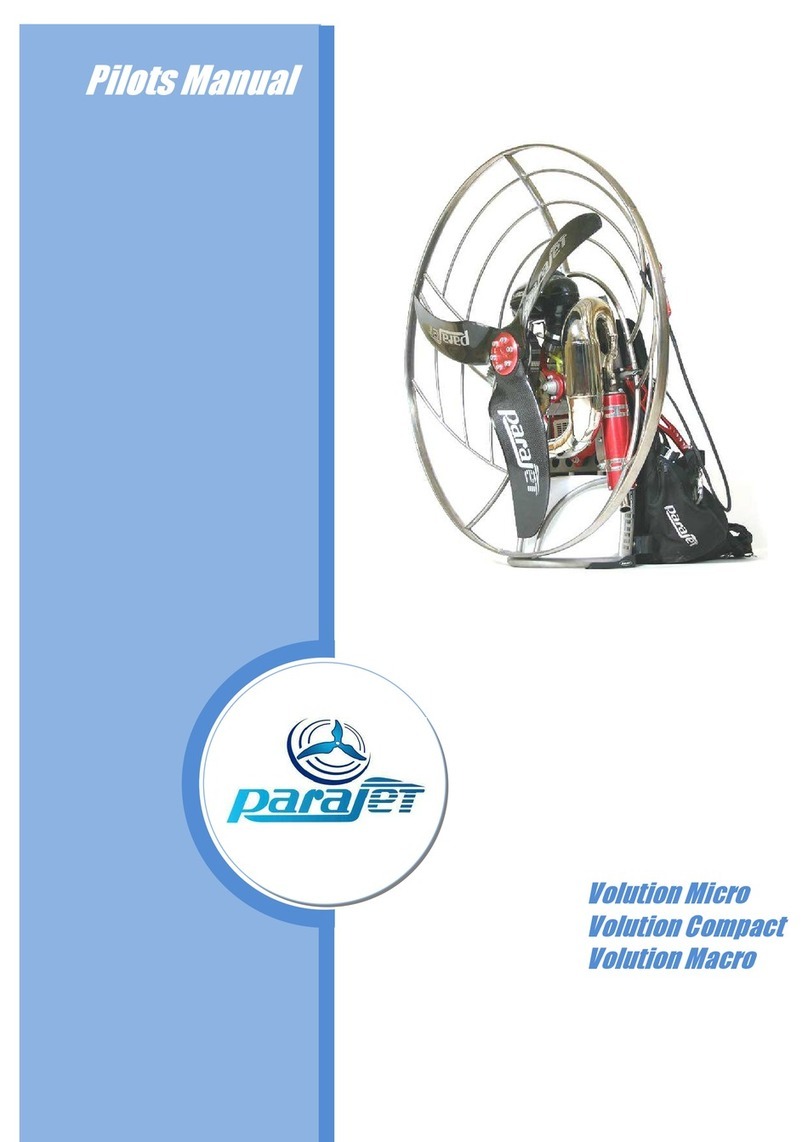
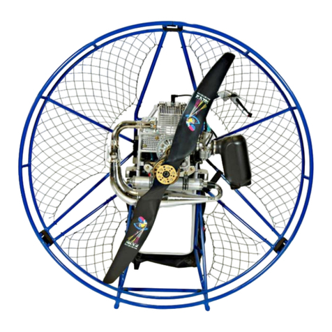
Parajet Cyclone 160 Manual

Pilots
Manual
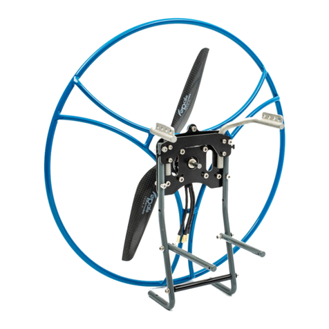
Cyclone 160

2
WARNING!!! Use of the powered paraglider is at your own risk.
WARNING!!!
YOU MUST READ THIS MANUAL AND AGREE TO THE CONDITIONS OF USE
BEFORE USING YOUR PARAJET CYCLONE 160
Bear in mind that you will use the Parajet Cyclone and paraglider at your
own risk. The Cyclone 160 is an extremely powerful Paramotor and should
e used only under direct tuition of a qualified instructor or y a pilot that
has received and passed a Paramotor course equivalent to the BHPA
Paramotor course. Due to the inherent risk in flying the Cyclone or any
motorized paraglider, no guarantee of any kind can e made against
accidents, odily injury and/or death. Be sure, therefore, to make all
required checks on the power unit and paraglider efore every flight. Never
try to fly if you find any part of your Cyclone damaged or suspect a
malfunction.
NB. This manual is NOT a substitute for flight training. Proper training is essential.
The Cyclone 160 is powerful enough to stall your wing exercise extreme caution when
flying with this unit.
This engine has een designed to work with Mo il One Racing 2T Fully Synthetic 2
stroke racing oil. 2 stroke oil can vary hugely in its composition and the wrong oil will
damage the engine and can result in engine malfunction. Failure to use Parajet’s
recommended 2 Stroke oil will result in the engine warranty eing void.

3
WARNING!!! Use of the powered paraglider is at your own risk.
NTRODUCTION
Congratulations on the purchase of your Parajet Cyclone 160 for motorized
paragliding. We guarantee you have made an excellent choice and wish you
many enjoya le flights and just as many safe landings with your Cyclone
160.
Our power units have een designed and produced in our UK factory to
exacting standards. Each Cyclone 160 is carefully inspected efore leaving
the factory. This manual and Parajet power unit carry a placard that clearly
indicates a limit to flight hours. Therefore, use your Cyclone 160 within the
limits indicated.
Should the purchaser modify the Cyclone 160 so as to change its original
specifications, the manufacturer’s warranty ecomes invalid.
Please read and e sure that you thoroughly understand this manual efore
flying the Cyclone 160. If there is any terminology or anything else in this
manual which you do not understand, please contact your dealer for
clarification.

4
WARNING!!! Use of the powered paraglider is at your own risk.
Table of Contents
WARNING!!! ................................................................................................ 2
PRE-FLIGHT CHECKS ..................................................................................... 5
FLIGHT SAFETY PRECAUTIONS ...................................................................... 6
SOME GOLDEN RULES !!! ............................................................................. 7
PRE-ASSEMBLY CHECK ................................................................................. 8
List of Components......................................................................................................... 8
FITTING THE RADIATOR ............................................................................... 9
F ll ng the rad ator. .................................................................................... 14
FITTING THE PROPELLER BLADES ............................................................... 16
ASSEMBLING THE 3-PIECE PROPELLER GUARD ........................................... 17
Charg ng the Cyclone L Po battery: ............................................................ 18
REDUCTION BELT ADJUSTMENT ................................................................. 19
FITTING THE WEIGHT-SHIFT HARNESS ....................................................... 20
ADJUSTING THE WEIGHT SHIFT HARNESS........................................................ 21
MIXING FUEL AND OIL ............................................................................... 22
Caution!..................................................................................................................... 23
PRIOR TO STARTING THE ENGINE .............................................................. 24
Warning!!! - Stay Clear of this Area !!! ..................................................................... 24
STARTING THE ENGINE AND ENGINE TEMPERATURE ................................. 25
STOPPING THE ENGINE........................................................................................... 28
RE-STARTING THE ENGINE.................................................................................... 28
ENGINE TEMPERATURE.......................................................................................... 29
CARBURETOR ADJUSTMENT ...................................................................... 30
ENGINE RUNNING IN PROCEDURE ............................................................. 31
MAINTENANCE SCHEDULE ......................................................................... 33
EVERY 5 HOURS........................................................................................................ 33
EVERY 10 HOURS...................................................................................................... 34
EVERY 50 HOURS...................................................................................................... 34
TROUBLE SHOOTING .................................................................................. 34
STORAGE FOR A LONG PERIOD AND USE THEREAFTER .............................. 35
5
WARNING!!! Use of the powered paraglider is at your own risk.
PRE-FLIGHT CHECKS
(every 5 – 10 hours of flying)
1 Frame/ Prop
Guard Check for loose olts/nuts or cracks
2 Harness Check all elts, material for tears, worn or urnt parts of harness.
3 Propeller Check for cracks, chips in lades; sufficient prop and guard
clearance; loose or missing prop olts/nuts.
4 Gas tank
Remove cap, check inside and outside for cracks and holes. Check
olts are tight on top of tank. Check fuel line for scuffs or kinks.
Remove dirt or change filter if lockage is discovered.
5 Crankshaft Turn prop slowly, listen for compression and check for “grinding
metal” sound
6 Reduction unit Check for loose olts and excess play in propeller shaft earings.
7 Reduction elt Check for proper tracking, elt squarely in Pulley track. Look for
cracks or worn spots on elt.
8 Rotor Block Check for cracks and oil leakage.
9 Spark plugs Check gap clearance (0.8 mm ± 0.1) check for urnt electrodes and
car on deposits. (every 10 hours)
10 Throttle lever Throttle lever/ca le move smoothly and return.
11 Kill switch Button depresses and returns.
12 Starter motor Pinion gear activates and returns. Grease if necessary.
13 Electrics Check for roken wires and loose connections.
14 Battery terminals Check for loose terminals, heat u les, corrosion etc.
15 Car uretor
settings
Check idling, and full power rpm settings. Adjust as directed in this
manual- see Car uretor Adjustments.

6
WARNING!!! Use of the powered paraglider is at your own risk.
FLIGHT SAFETY PRECAUTIONS
•The Parajet Cyclone 160 engine has een run-in prior to shipment. This means that
your Cyclone 160 is ready to fly. It is important however that excessive throttle is
NOT used for at least the first 10 hours of flying. For example, do NOT depress the
throttle fully for more than 30 seconds at a time. A well run in engine will
outperform an engine that has een run at full power for long periods right from the
start. You can potentially damage a new engine with excessive throttle.
•The Cyclone 160 Paramotor unit is to e used only after having received adequate
and proper training from a qualified motor paragliding instructor.
•Max weight capacities for paramotor pilots flying a Parajet Cyclone 160 range
paramotor:
Parajet
Cyclone 160
Model
Max Pilot Weight
Macro
250
Kg
•The Cyclone 160 should only e used with canopies designed for motor paragliding.
•Always conduct a check of all components efore every flight.
•Always wear a helmet, flight shoes and gloves when flying the Cyclone 160.
•Always stay clear of moving parts such as propellers, pulleys and elt.
•Always stay clear of hot engine parts and muffler.
•Do not fly low level over water, woodland, or potentially hazardous landing
areas. Do not fly into controlled airspace or over built up areas, it essential
always to consider a safe landing area should you experience an engine failure or
loss of power.
•Before starting the engine check the area is clear and shout “CLEAR PROP”
•Always ensure that the power unit is switched off when not in use. The main power
switch is to e found on the left side of the machine just ehind the harness.

7
WARNING!!! Use of the powered paraglider is at your own risk.
SOME GOLDEN RULES !!!
1. Never place your engine downwind of your wing.
2. Have you enough fuel to get there? Better too much than too little!
3. Check for any loose articles that could trail or fall into the propeller while flying and
fasten them securely.
4. If you spot a pro lem, not matter how small, deal with it NOW!
5. Always put on and fasten your helmet efore clipping into the harness.
6. Always carry out full pre-flight checks efore launching.
7. Don’t fly into danger – over water, tree, power lines etc where an engine failure will
leave you in trou le.
8. Try not to fly in the tur ulence of your own wake or that of others, especially at low
altitude.
9. Except for collision avoidance, making a sharp turn against the torque effect during
steep clim s can e dangerous: you may rapidly stall and enter a spin.
10. Avoid downwind low flying: it drastically reduces your options.
11. Be sensitive to mechanical pro lems early. A noticea le change in engine tone or a
new vi ration may spell trou le. Land and check it out!
12. Remem er, not everyone enjoys your engine noise. Care must e taken when flying
near livestock.
13. Never take-off towards areas of potential rotor, towards trees or uildings on the
lee side of a hill.
14. Never touch any part of the propeller guard when the engine is running.
15. Always e aware of the weather, never fly if large cumulus clouds are rewing and
never fly in the rain.
17. Never fly elow the lee side of a hill, rotor is dangerous!!

8
WARNING!!! Use of the powered paraglider is at your own risk.
PRE-ASSEMBLY CHECK
Be sure to identify all components after unpacking your Cyclone 160 unit. If any parts
are found defective do not assem le. Contact your dealer or the manufacturer
immediately.
Parajet International Ltd: Main enquiry Line + 44 1747 861368
List of Components
1. Main Chassis 8. 3 Piece Propeller Guard
2. Drive Pulley 9. Radiator
3. Propeller Retaining Disc 10. Air Box and Car urettor
4. Main Rotor Housing 10. Car on Fi re Propeller Blade
5. Main On/Off Switch 12. Muffler and Exhaust Pipe
6. Harness 13. Fuel Filler Cap
7. Ru er Skid Pads 14. Fuel Tank
10
11
6
5
13
12
8
2
7
4
3
1
9
14

9
WARNING!!! Use of the powered paraglider is at your own risk.
FITTING THE RADIATOR
Your Parajet Cyclone 160 paramotor and radiator will arrive unassembled. This is
the critical coolant system for the engine and must be installed correctly. Any
leakage will lead to engine damage.
Start this process before fitting the cage and propellers.
Parts:
Step 1
Mixing engine coolant.
A good quality anti freeze/summer coolant should be used and mixed to the
manufacturers recommendations.
In a separate container Mix up 2 litres of coolant/water solution ready for filling up
the machine. You will not require all two litres.
This should be decanted in to a convenient pouring device ready for filling up the
machine.
Jubilee Clip
Radiator Hose
Radiator Filler Cap
Radiator

10
WARNING!!! Use of the powered paraglider is at your own risk.
Step 2
With the Parajet Rotron Macro 160 paramotor stood upright orientate the radiator
so the radiator mountings line up with their corresponding mounts on the frame.
The radiator will only fit on in one direction.
Facing the propeller side of the engine (not the harness side), the filler neck of
the radiator will be on the left of the radiator.
Pass the tubular legs of the radiator through the plastic mountings in the frame
and firmly push on top of the radiator to locate it in its mounts.
Picture 1

11
WARNING!!! Use of the powered paraglider is at your own risk.
Picture 2. The fitting the radiator in the correct orientation.
Step 3
both radiator hose inlet and outlet are fitted to the engine. They will however
need to be fitted to the radiator.
First feed the jubilee clips over the radiator hose. Then slip the radiator inlet and
outlet hoses over the radiator tubes which protrude through the plastic chassis
mounts. Make sure they are firmly stopped against the plastic frame mounts.
The jubilee clip should be positioned 1cm from the end of the coolant hose on
both the inlet and outlet hose side.
Using a large flat head screw driver tighten the jubilee clip to ensure there can be
no leakage of coolent.

12
WARNING!!! Use of the powered paraglider is at your own risk.
Picture 3. The fitted radiator hoses with the jubilee clips installed.
Picture 4

13
WARNING!!! Use of the powered paraglider is at your own risk.
Step 4
Fit the radiator cap on to the radiator
The radiator cap is already attached to the black overflow pipe.
Picture 5.

14
WARNING!!! Use of the powered paraglider is at your own risk.
Filling the r di tor.
Warning Engine should not be flown without the radiator being filled.
Failure to do so will result in engine malfunction which will void the
warranty. This may also lead to injury or death.
Warning never open the radiator cap when the engine is hot this may cause
injury
Warning engine coolant can be corrosive and must be washed of if spilt on
the paramotor.
Filling the paramotor with coolant can be done with the cage and propeller
installed.
The paramotor can be rolled on to its side so the filler neck is the highest point of
the system, this is best done with two people, one to support the paramotor and
one to fill it up.
Caution: To avoid damage to paint this should be done on a soft surface,
cardboard or a rubber mat.
Remove the radiator cap. Roll the paramotor on to its side as shown bellow.
Picture 8. Showing the paramotor being filled.
The radiator should be slowly filled to the brim with coolant.
Once full refit the radiator cap before rolling the paramotor back on to its base.
You should run the engine for one minute and the leave it to cool down

15
WARNING!!! Use of the powered paraglider is at your own risk.
Check the paramotor rigorously for any sign of leakage from the installed parts
Then do the coolant filling procedure again to check the radiator is full to the brim
and if required refill. This running helps bleeds any air out of the system.
Once refilled refit the radiator cap and roll the paramotor on to its base.
Your coolant system is now fitted, full and ready for use.

16
WARNING!!! Use of the powered paraglider is at your own risk.
FITTING THE PROPELLER BLADES
Fit the 3 propeller lades to the driven pulley in the order outlined elow
1. Insert 2 of the 6 (M8 x 60mm) olts into the prop disc and locate a single lade in
position. Ensure that each olt has oth a split spring washer then normal spreader
washer located on its shank efore locating in the prop disc.
2. Locate a single lade in position on these two olts and lightly screw the olts into
position on the driven pulley.
3. Follow the same procedure for each lade ut do not tighten the olts until all three
lades are in position.
4. Finally tighten each olt with equal torque hand tight only ( e careful not to over
tighten and crush the car on fi re propeller hu s)
Note – When nstall ng the propeller, the propeller blade bolts should not be over-
t ghtened or the base of the propellers could be damaged, d storted and weakened.
When installing the propeller blades make sure to match the balancing dots on each blade
with the corresponding dots on the adjacent blade. The dots can be located on at the bas
of each blade.
Prop Disc
M8 x 60
Screws
Driven
Pulley
Propell
er Blade

17
WARNING!!! Use of the powered paraglider is at your own risk.
ASSEMBLING THE 3-PIECE PROPELLER GUARD
Fit the three pieces together as shown in the illustration elow. The two lower sections should
e clicked into position first. The top section can then e clicked into position, to do this lightly
press the curved central support onto its aerofoil connector and simultaneously locate the two
circular side connectors. DO NOT PRESS FIRMLY INTO POSITION UNTIL THE OUTER RING
CONNECTORS ARE LOCATED. Next locate the left and right hand outer ring connectors. Lightly
press them into position ut do not depress the utton clips. Now that all the connection points
are in position, the central upright should e firmly pressed into position and the utton clip
depressed to lock this position. The outer ring connectors can now e locked in also. This
process require a little technique, ut once developed can e snapped together and
disassem led in under a minute. This is the fastest and most dura le design of propeller guard.
Note - The propeller guard is designed to prevent canopy lines and other foreign o jects from
eing drawn into the propeller and are not intended to protect the pilot. Therefore,
always use extreme caution and never touch any part of the propeller guard while flying or
running the engine on the ground.
Left
: Internal guard
vertical support slots
through chassis holder
efore lower connectors
are locked in position
Right: Upper cage
support is located efore
eing snapped firmly into
position.

18
WARNING!!! Use of the powered paraglider is at your own risk.
Ch rging the Cyclone LiPo b ttery:
Important! Caution! Always disconnect the attery connector when not using the
Cyclone for more than 4 days. If you do not you will risk damaging the attery.
WARNING: Do not try to start your engine if the attery is showing signs of running
low. The starter motor will start to spin slower, due to the nature of LiPo atteries
they drain very quickly once the voltage drops elow a certain level. If you continue to
try starting the engine once the attery voltage has dropped you will risk damaging
the attery or starter motor seriously.
Your Parajet Cyclone is supplied with a 14.8volt high power Lithium Polymer attery. This type
of attery has the highest energy density of any type of attery availa le today. It also has many
other advantages such as
1. It can e fully charged in under one hour
2. It has an extremely high discharge rate, delivering fully energy to the start motor
instantly which results in the easiest start procedure
3. The attery is extremely light weight and compact and can deliver over 80 starts on a
single charge
Charge procedure
1. Switch on Battery Charger y:
a. Plugging in the mains 240volt or 110volt power lead (lead supplied in ox)
2. Using the ‘Batt Type’ utton press until ‘LiPo’ is displayed on the screen
3. Press the ‘ENTER Start/Stop’ utton to set the charging amps and num er of cells. Use
the Inc + utton to set the figures as follows:
4. 4.0A 4CL (The charger must first read these figures to charge correctly)
5. Plug the attery you wish to charge into the charger y first connecting the small white
multi pin plug into the 4S socket on the small adaptor oard supplied. Then connect the
larger lue attery terminal plug to the charger
6. Once oth attery connectors are connected press and hold the ENTER Start/Stop
utton for 3 seconds and the charge and alance procedure will egin.
IMPORTANT: Stop using the attery once the cranking speed has clearly reduced and
re-charge the attery.
IMPORTANT: You should charge the attery using the procedure descri ed a ove
every time you charge as this will keep the attery in the est possi le condition. This
is known as alance charging your attery and it maintains each individual cell within
the attery pack from ecoming damaged due to voltage im alance.

19
WARNING!!! Use of the powered paraglider is at your own risk.
REDUCTION BELT ADJUSTMENT
The transmission elt is well adjusted at the time of shipment, ut it could ecome slack
during initial operations. When necessary adjust it so as to keep it always in an optimum
state of tension. Referring to the picture elow adjust reduction elt tension as outlined
in these steps. A high pitch revving noise from the engine is a sign that the elt has
ecome loose. Be sure to tighten the elt as soon as possi le or you could damage it.
1. Remove the propeller from the driven pulley.
2. Loosen the prop shaft retaining nut and then screw (A) NB. They will e very tight!!
3. Insert the 5mm hex key into the hole in the side of the prop shaft. (B)
4. To tension the elt, firmly rotate the shaft clockwise. This in turn will ena le the
eentric prop shaft to increase the elt tension. It will e very stiff to move.
5. Once the elt has reached the required tension simply re-tighten the prop shaft
retaining screw and nylock nut. (see diagram elow for elt tension setting)
A
B
Left
:
Prop Shaft
retaining screw also
has a nylock security
nut on the opposite
end. Loosen this 4
turns efore undoing
main screw (A)
Right
:
Use 5 mm hex
key provided and slot
into drilled hole in
propeller shaft. Then
rotate propeller shaft
hard clockwise to
tighten or counter
clockwise to loosen.
Left
: Shows correct
elt
tension. You should e
a le to push 2 - 3mm
movement with your
thum .
2 – 3 mm

20
WARNING!!! Use of the powered paraglider is at your own risk.
FITTING THE WEIGHT-SHIFT HARNESS
The weight-shift design ena les pilots to control flight direction purely y shifting centre
of gravity in the harness. To do this simply lean in the desired direction and swing one
leg over the other to aentuate the turn. This creates a very efficient smooth turn which
requires no rake input.
Fitting the weight-shift harness:
1. Start y locking the harnesses upper
retaining ar onto the chassis as shown
elow. NB. Ensure Button Clip locates
properly and pops into hole as arrowed..
2. At the ase of the harness on the
reverse side there are 2 steel rings
pressed into the we ing ta s. These
line up with 2 corresponding M6
threaded inserts located in each chassis
upright approximately 10cm from the
ase.
3. Using the two M6 x 12mm socket screws
and large flange washers tighten the harness
we ing into position against the chassis
uprights.
4. At the front of the harness are 2 we ing
loops. Using the stainless steel shackles
attached to the swing arms attach the
we ing loops to the first hole in the swing
arm.
5. Attach cara iner connection points to the
corresponding weight setting on the swing
arms. (See next page)
Table of contents
Other Parajet Paramotor manuals