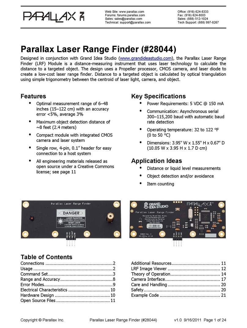
Parallax 28044 User manual

Web Site: www.parallax.com
Forums: forums.parallax.com
Sales: sales@parallax.com
Technical: support@parallax.com
Office: (916) 624-8333
Fax: (916) 624-8003
Sales: (888) 512-1024
Tech Support: (888) 997-8267
Copyright © Parallax Inc. Parallax Laser Range Finder (#28044) v2.0 10/31/2015 Page 1 of 23
Parallax Laser Range Finder (#28044)
Designed in conjunction with Grand Idea Studio (www.grandideastudio.com), the Parallax Laser Range
Finder (LRF) Module is a distance-measuring instrument that uses laser technology to calculate the
distance to a targeted object. The design uses a multicore Propeller microcontroller, CMOS camera, and
laser diode to create a low-cost laser range finder. Distance to a targeted object is calculated by optical
triangulation using simple trigonometry between the centroid of laser light, camera, and object.
Features
Optimal measurement range of 6–48
inches (15–122 cm) with an accuracy
error <5%, average 3%
Maximum object detection distance of
~8 feet (2.54 meters)
Range finding sample rate of 5 Hz
Compact module with integrated CMOS
camera and laser diode
Single row, 4-pin, 0.1” header for easy
connection to a host system
All engineering materials released as
open source under a Creative Commons
license; see page 23
Key Specifications
Power requirements: 5 VDC @ 150 mA
Communication: Asynchronous serial
300–115,200 baud with automatic baud
rate detection
Operating temperature: 32 to 122 °F
(0 to 50 °C)
Dimensions: 3.95" W x 1.55" H x 0.67" D
(10.05 W x 3.95 H x 1.7 D cm)
Application Ideas
Distance or liquid level measurements
Object detection and/or avoidance
Item counting
Table of Contents
Connections....................................................2
Usage ............................................................2
Command Set.................................................3
Range and Accuracy......................................10
Error Modes..................................................10
Electrical Characteristics................................11
LRF Image Viewer.........................................12
Hardware Design ..........................................15
Theory of Operation......................................16
Camera Interface..........................................19
Care and Handling ........................................22
Safety ..........................................................22
Open Source Files and Example Code.............23
Revision History............................................23

Copyright © Parallax Inc. Parallax Laser Range Finder (#28044) v2.0 10/31/2015 Page 2 of 23
Connections
The LRF Module interfaces to any host microcontroller or computer system using only four connections
(GND, VCC, SOUT, SIN).
Pin
Name
Type
Function
1
GND
G
System ground. Connect to power supply’s ground (GND) terminal.
2
VCC
P
System power. 5 VDC input.
3
SOUT
O
Serial output to host. 5 V TTL-level interface, non-inverted, 8 data bits, no
parity, 1 stop bit, baud rate matched to host.
4 SIN I Serial input from host. 3.3 V to 5 V TTL-level interface, non-inverted, 8 data
bits, no parity, 1 stop bit, baud rate matched to host.
Type: I = Input, O = Output, P = Power, G = Ground
Use the following example circuit for connecting the Parallax Laser Range Finder Module:
Usage
The LRF Module is controlled by the host via a serial communications interface. To use, simply align the
LRF Module towards the target object and send the desired command.
The serial interface is configured for 8 data bits, no parity, 1 stop bit (8N1). Automatic baud rate
detection occurs on initial power-up of the LRF Module. The Module waits for a “U” character to be sent
by the host and will set its baud rate to match that of the host. Supported baud rates include 300, 600,
1200, 2400, 4800, 9600, 19200, 38400, 57600, and 115200.
When the LRF is ready to receive commands, it will send a “:” to the host. The LRF waits in an idle state
until it receives a valid command, at which time it performs the command and returns command-specific
data (if any). The LRF will return a “?” upon receiving an invalid command.

Copyright © Parallax Inc. Parallax Laser Range Finder (#28044) v2.0 10/31/2015 Page 3 of 23
The camera system used in the LRF Module has automatic white balance, automatic exposure, and
automatic gain control enabled by default, and will automatically adjust its image to account for sudden
changes in lighting conditions. However, the LRF works best in a controlled environment, such as indoors
with minimal changes in brightness across the frame. The LRF is also less reliable when the laser is
shining onto a bright object (for example, a white piece of paper), since the background subtraction
performed during image processing could potentially “subtract” the bright laser from the already bright
frame.
Status Indicator
A visual indication of the LRF Module’s operating state is given with the on-board LED (Light-Emitting
Diode). The LED is located on the back side of the LRF near the center of the board. The LED denotes
four states of the LRF:
1. Green: Idle state. Waiting for a command to be sent by the host.
2. Red: Active state. For example, performing a range calculation or capturing an image with the
camera.
3. Orange (Solid): Baud rate detection state. The LRF is waiting for a “U” character to be sent by
the host in order to automatically set the communications baud rate. Occurs on LRF power-up
only.
4. Orange (Blinking): Error state. The LRF has malfunctioned. A message identifying the failed
operation will be transmitted on the SOUT (Serial Out) pin. See Error Modes, page 10, for details.
If the LED is OFF, the LRF may not be receiving power.
Command Set
All commands are single-byte, ASCII printable values and are not case-sensitive (upper case and lower
case will both work). No carriage return (CR) or linefeed (LF) is required after the command byte is sent.
Depending on the command, data may be returned by the LRF.
The command descriptions in this section are for LRF firmware version 2.0. For command descriptions of
earlier firmware versions, refer to product manual version 1.1. Examples are shown for direct connection
to a microcontroller (BASIC Stamp 2) and/or to a host PC via a terminal program.
Basic Commands
R Single range measurement (returns a 4-digit ASCII value in millimeters)
B Single range measurement (returns a 2-byte binary value in millimeters)
L Repeated range measurement (any subsequent byte will stop the loop)
E Adjust camera for current lighting conditions
S Reset camera to initial settings
T Toggle laser on/off
V Display version information
H Display available commands

Copyright © Parallax Inc. Parallax Laser Range Finder (#28044) v2.0 10/31/2015 Page 4 of 23
Advanced Commands
O Display coordinate, mass, and centroid information for all detected blobs
X Calibrate camera system for range finding
A Adjust blob detection parameters
G Capture & send single frame (160x128, 8 bits/pixel grayscale)
C Capture & send single frame (320x16, 8 bits/pixel grayscale) w/ laser enabled
P
Capture & send processed frame (320x16, 8 bits/pixel grayscale) w/ background
subtraction
Command Details
R: Single range measurement (ASCII)
Takes a single range finding measurement and returns the distance to the target object as a printable
ASCII string (“D = ”) with a
4-digit decimal
value in millimeters. A range measurement takes ~200
milliseconds to complete.
The LRF Module is most accurate within its optimal measurement range of 6–48 inches (15–122 cm). In
ideal conditions, a distance measurement of up to ~8 feet (2.54 meters) may be possible. While the
accuracy will be hindered at distances outside of the optimal range, the LRF could still be used for gross
distance measurements or simple object detection. See Range and Accuracy, page 10, for details.
Terminal Example:
:R
D = 0288 mm
:
BS2 Example:
SEROUT LRF_TX, LrfBaud, ["R"] ' Send command
' Wait for distance measurement and store it as a decimal value
SERIN LRF_RX, LrfBaud, 3000, No_Response, [WAIT("D = "), DEC4 range]
B: Single range measurement (binary)
Takes a single range finding measurement and returns the distance to the target object as a
2-byte
binary
value in millimeters. Data is sent MSB first. A range measurement takes ~200 milliseconds to
complete.
The LRF Module is most accurate within its optimal measurement range of 6–48 inches (15–122 cm). In
ideal conditions, a distance measurement of up to ~8 feet (2.54 meters) may be possible. While the
accuracy will be hindered at distances outside of the optimal range, the LRF could still be used for gross
distance measurements or simple object detection. See Range and Accuracy, page 10, for details.
Terminal Example:
:B
<binary data>
:
BS2 Example:
SEROUT LRF_TX, LrfBaud, ["B"] ' Send command
SERIN LRF_RX, LrfBaud, 3000, No_Response, [range.HIGHBYTE, range.LOWBYTE]

Copyright © Parallax Inc. Parallax Laser Range Finder (#28044) v2.0 10/31/2015 Page 5 of 23
L: Repeated range measurement
Continuously calls the Single range measurement (ASCII) command (“R”). Once the loop has started, any
subsequent byte sent to the LRF Module will stop the command. Each range measurement takes ~200
milliseconds to complete.
Terminal Example:
:L
D = 0288 mm
D = 0289 mm
D = 0289 mm
D = 0289 mm
<any key pressed>
:
E: Adjust camera for current lighting conditions
Calibrates the LRF Module’s camera for the current lighting conditions. This may aid the camera in
successfully detecting the laser spot within the frame, which increases accuracy of the range finding
functionality.
The command first ensures that automatic white balance (AWB), automatic exposure control (AEC), and
automatic gain control (AGC) are enabled. Then, after a 10 second delay for the camera image to settle,
AWB, AEC, and AGC are disabled. The EV/exposure level is also reduced to a minimum value. This will
cause the entire camera frame, including any previously bright areas, to appear dark. A bright laser spot
may now be more easily identifiable within the frame.
The camera’s settings can be reset to their default with the “S” command.
Terminal Example:
:E
<short delay>
:
BS2 Example:
SEROUT LRF_TX, LrfBaud, ["E"]
SERIN LRF_RX, LrfBaud, [WAIT(":")]
S: Reset camera to initial settings
Resets and initializes the LRF Module’s camera to its default, power-up configuration, including enabling
automatic white balance (AWB), automatic exposure control (AEC), and automatic gain control (AGC). It
may take up to 10 seconds for the camera image to settle after the command is sent.
This command is particularly helpful when the “E” command has been used to adjust the camera for
current lighting conditions and the user wishes to reset the camera settings without power cycling the
LRF Module.
Terminal Example:
:S
:
BS2 Example:
SEROUT LRF_TX, LrfBaud, ["S"]
SERIN LRF_RX, LrfBaud, [WAIT(":")]

Copyright © Parallax Inc. Parallax Laser Range Finder (#28044) v2.0 10/31/2015 Page 6 of 23
T: Toggle laser on/off
Allows for manual control of the laser diode. The command will toggle the laser diode on and off.
Commands that make use of the laser diode (“R”, “B”, “L”, “O”, “X”, “C”, and “P”) will supersede the state
set using this command.
Terminal Example:
:T
<laser diode on>
:T
<laser diode off>
:
BS2 Example:
SEROUT LRF_TX, LrfBaud, ["T"] ' Turn laser diode on
SERIN LRF_RX, LrfBaud, [WAIT(":")]
SEROUT LRF_TX, LrfBaud, ["T"] ' Turn laser diode off
SERIN LRF_RX, LrfBaud, [WAIT(":")]
V: Display version information
Lists version and calibration information for the LRF Module. This data is useful for troubleshooting and
debugging.
FW: Firmware revision (major.minor)
MFG and PID: Manufacturer ID and Product ID of the LRF’s on-board camera
SLOPE, INTERCEPT, PFC_MIN: Device-specific values calculated during the calibration process
(“X”) and used for range finding (if the LRF Module is uncalibrated, the values will all be
0xFFFFFFFF)
LOWER_BOUND, UPPER_BOUND, BLOB_MASS_THRESHOLD: Parameters used for blob detection
during the range finding process. The values default to those shown in the example output
below, but can be changed using the “A” command.
Terminal Example:
:V
Parallax Laser Range Finder
Designed by Grand Idea Studio [www.grandideastudio.com]
FW = 2.0
MFG = 7FA2
PID = 7691
SLOPE = +0.001418615 (3AB9F0CE)
INT = -0.009308979 (BC1884B0)
PFC_MIN = 28
LOWER_BOUND = 50
UPPER_BOUND = 255
BLOB_MASS_THRESHOLD = 16
:

Copyright © Parallax Inc. Parallax Laser Range Finder (#28044) v2.0 10/31/2015 Page 7 of 23
H: Display available commands
Lists all available commands that the LRF Module supports.
Terminal Example:
:H
Basic Commands:
R Single range measurement
B Single range measurement (binary response, 2 bytes)
L Repeated range measurement (any subsequent byte will stop the loop)
<more commands listed, but not shown in this manual>
:
O: Display coordinate, mass, and centroid information for all detected blobs
Displays coordinate, mass, and centroid (center of mass) information for up to 6 detected blobs within
the camera’s field-of-view. This information can be used for custom image processing or object detection
outside of the standard LRF Module functionality. The blob detection begins on the left side of the frame
and “scans” to the right. See Image Processing and Blob Detection, page 20, for details.
L: X coordinate of the beginning (left side) of the detected blob
R: X coordinate of the end (right side) of the detected blob
M: Mass of blob (sum of all valid pixels within the blob)
C: Centroid (center of mass) of blob
<: Marker to indicate if the blob is less than the BLOB_MASS_THRESHOLD
*: Marker to indicate the blob with the largest mass (primary blob)
In many cases, if a single blob is detected within the frame, it is likely the laser spot. In other cases,
there may be reflections of the laser light or other spots that are not related to the laser. Generally, the
blob with the largest mass within the frame can be considered the actual laser spot.
Terminal Example:
:O
0: L = 81 R = 88 M = 14 C = 84 <
1: L = 137 R = 232 M = 917 C = 181 *
2: L = 235 R = 254 M = 170 C = 244
:
X: Calibrate camera system for range finding
To account for manufacturing and assembly variances, particularly related to the camera and laser diode
alignments, each LRF Module must be calibrated. This occurs during production, but the LRF can be re-
calibrated by the user at a later date if desired. If a new major version of firmware is loaded (for
example, upgrading from firmware version 1.0 to 2.0), the LRF will need to be re-calibrated.
The calibration routine requires the user to place the LRF Module at 6 fixed distances (from 20 cm to 70
cm at 10 cm intervals), measured from the front face of the LRF circuit board. The LRF takes
measurements at each distance and calculates the SLOPE, INTERCEPT, and PFC_MIN values. The values
are then stored in an unused portion of the non-volatile boot Serial EEPROM. They will remain intact
during a power cycle.

Copyright © Parallax Inc. Parallax Laser Range Finder (#28044) v2.0 10/31/2015 Page 8 of 23
The SLOPE and INTERCEPT are used to convert the pixel offset to an angle using a best-fit slope-
intercept linear equation. The PFC_MIN value is used to set the maximum allowable distance of the LRF
Module, which is represented by a minimum pixels from center value. See Optical Triangulation, page 17,
for details.
The LOWER_BOUND, UPPER_BOUND, and BLOB_MASS_THRESHOLD parameters, used for blob detection
during range finding, are reset to their default values during this process (50, 255, and 16, respectively).
A video demonstrating the calibration process can be found on YouTube:
www.youtube.com/watch?v=1gk_tRbJO84
Terminal Example:
:X
Are you sure you want to calibrate (Y/N)?Y
Set LRF to D = 20 cm and press spacebar (any other key to abort)
pfc: 289 angle: 0.3718561
pfc: 290 angle: 0.3718561
pfc: 289 angle: 0.3718561
< more steps listed, but not shown in this manual >
Set LRF to D = 70 cm and press spacebar (any other key to abort)
pfc: 105 angle: 0.1109708
SLOPE = +0.001420366 (3ABA2B96)
INT = -0.03679396 (BD16B544)
PFC_MIN = 48
LOWER_BOUND = 50
UPPER_BOUND = 255
BLOB_MASS_THRESHOLD = 16
Write new values (Y/N)?Y
:
A: Adjust blob detection parameters
Receive new blob detection parameters from the user and store them in memory. The current value is
displayed within the square brackets ([]). Each parameter can have a value from 0 to 255 and must be
followed by a carriage return (CR). If the entered value is out of range, an error message will be
displayed and the command will abort. When all parameters have been properly entered, they are stored
in an unused portion of the non-volatile boot Serial EEPROM. They will remain intact during a power
cycle.
LOWER_BOUND is the minimum brightness value and UPPER_BOUND is the maximum brightness value
used during the thresholding phase of blob detection. If a pixel within the processed frame is greater
than or equal to LOWER_BOUND (default of 50) and less than or equal to UPPER_BOUND (default of
255), it is set to ‘1’ (white) and included in the column sum. Otherwise, it is set to ‘0’ (black).
BLOB_MASS_THRESHOLD is the minimum blob mass (the number of valid ‘1’ pixels within the total blob)
required for the blob to be considered as the primary blob. If the blob mass is greater than or equal to
BLOB_MASS_THRESHOLD (default 16), it is included. This parameter reduces the chance of using an
unlikely blob (such as one caused by optical noise or reflection) for range finding calculations.
See Image Processing and Blob Detection, page 20, for details.

Copyright © Parallax Inc. Parallax Laser Range Finder (#28044) v2.0 10/31/2015 Page 9 of 23
Terminal Example:
:A
Enter new LOWER_BOUND [50]: 40
Enter new UPPER_BOUND [255]: 200
Enter new BLOB_MASS_THRESHOLD [16]: 30
:
G: Capture & send single frame (160x128, 8 bits/pixel grayscale)
Capture a 160x128 resolution grayscale image with the LRF Module’s camera and return the data in a
binary format.
The data is sent MSB first, one byte per pixel, starting at the upper-left pixel location (0,0), moving left to
right, top to bottom across the frame, and ending at the lower-right pixel location (160,128). Each byte
corresponds to the brightness value of a single pixel where 0x00 is black and 0xFF is white.
A total of 20,480 bytes of binary data is sent. An ASCII footer (“END”) is attached to the end of the
binary data stream to assist in identifying the end of the frame.
This command can be used from within the LRF Image Viewer tool to easily view the image.
Terminal Example:
:G
<binary data>END
:
C: Capture & send single frame (320x16, 8 bits/pixel grayscale) w/ laser enabled
Capture a 320x16 resolution grayscale image with the LRF Module’s camera and return the data in a
binary format. The laser diode is enabled during the frame grab for testing and alignment purposes.
The data is sent MSB first, one byte per pixel, starting at the upper-left pixel location (0,0), moving left to
right, top to bottom across the frame, and ending at the lower-right pixel location (320,16). Each byte
corresponds to the brightness value of a single pixel where 0x00 is black and 0xFF is white.
A total of 5,120 bytes of binary data is sent. An ASCII footer (“END”) is attached to the end of the binary
data stream to assist in identifying the end of frame.
This command can be used from within the LRF Image Viewer tool to easily view the image.
Terminal Example:
:C
<binary data>END
:
P: Capture & send processed frame (320x16, 8 bits/pixel grayscale)
Capture a 320x16 resolution processed image with the LRF Module’s camera and return the data in a
binary format. This mode is specific for range finding functionality and consists of a “background
subtracted” image where one frame is taken with the laser diode off, one frame taken with the laser
diode on, and the data of the two frames subtracted. This helps to isolate the laser spot within the frame.
See Image Processing and Blob Detection, page 20, for more details.
The data is sent MSB first, one byte per pixel, starting at the upper-left pixel location (0,0), moving left to
right, top to bottom across the frame, and ending at the lower-right pixel location (320,16). Each byte
corresponds to the brightness value of a single pixel where 0x00 is black and 0xFF is white.

Copyright © Parallax Inc. Parallax Laser Range Finder (#28044) v2.0 10/31/2015 Page 10 of 23
A total of 5,120 bytes of binary data is sent. An ASCII footer (“END”) is attached to the end of the binary
data stream to assist in identifying the end of frame.
This command can be used from within the LRF Image Viewer tool to easily view the image.
Terminal Example:
:P
<binary data>END
:
Range and Accuracy
The LRF Module is most accurate within its optimal measurement range of 6–48 inches (15–122 cm).
Within this range, error can span from zero (no difference between actual distance and the distance
calculated by the LRF) to 5%. On average, the error is approximately 3%.
Within the optimal measurement range, the horizontal position of the laser spot within the camera’s
frame (which is used to determine distance to the target object) changes noticeably. At longer distances,
although the camera can still “see” the laser spot, the horizontal position does not change as much,
causing a significant reduction in accuracy. Accuracy also varies with lighting conditions and material of
the target object, which affect the LRF Module’s capability to determine the laser spot within the camera’s
frame.
The LRF Module intentionally limits the maximum detectable distance to 100 inches (254 cm). At
distances less than 6 inches, the laser spot is out of the camera’s field-of-view, so no range calculation
can occur. See Optical Triangulation, page 17, for more details.
The following chart shows example measurements taken with a LRF Module. The Calculated Distance,
Difference (Δ), and % Error will vary slightly per unit.
Error Modes
In the event that the LRF enters the error state (signified by a blinking orange LED status indicator), an
ASCII message identifying the failed operation will be transmitted on the SOUT (Serial Out) pin.
Messages include:
ERR: cam.start. Error initializing the camera on LRF power-up. This may be caused by a
communication error between the Propeller and camera.
ERR: cam.init. Error performing the “S” command (Reset camera to initial settings). This may
be caused by a communication error between the Propeller and camera.

Copyright © Parallax Inc. Parallax Laser Range Finder (#28044) v2.0 10/31/2015 Page 11 of 23
ERR: cam.calibrate. Error performing the “E” command (Adjust camera for current lighting
conditions). This may be caused by a communication error between the Propeller and camera.
ERR: cam.setRes. Error setting the camera’s resolution. This may be caused by a
communication error between the Propeller and camera.
ERR: cam.getID. Error retrieving the camera’s manufacturer and product IDs. This may be
caused by a communication error between the Propeller and camera.
ERR: eeprom.ReadLong. Error reading calibration data from the external Serial EEPROM. This
may be caused by a communication error between the Propeller and EEPROM or an incorrect
type of EEPROM device.
ERR: eeprom.WriteLong. Error writing calibration data to the external Serial EEPROM. This
may be caused by a communication error between the Propeller and EEPROM or an incorrect
type of EEPROM device.
If the LRF is in an error state, but no error message is transmitted, then there is likely a failure with
starting either the serial communication or auto baud detection cog.
For further assistance, please contact Parallax technical support.
Electrical Characteristics
At VCC = +5.0 V and TA= 25 ºC unless otherwise noted.
Parameter Symbol Specification Unit
Min. Typical Max.
Supply Voltage
VCC 4.5 5.0 5.5 V
Supply Current, Idle
IIDLE --- 82 --- mA
Supply Current, Active
ICC --- 126 150 mA
Absolute Maximum Ratings
Condition
Value
Operating Temperature
0 ºC to +50 ºC (+32 ºF to +122 ºF)
Storage Temperature
-40 ºC to +125 ºC (-40 ºF to +257 ºF)
Supply Voltage (VCC)
+4.5 V to +5.5 V
Ground Voltage (VSS)
0 V
Voltage on any pin with respect to VSS
-0.3 V to +7.0 V
NOTICE: Stresses above those listed under “Absolute Maximum Ratings” may cause permanent damage
to the device. This is a stress rating only and functional operation of the device at those or any other
conditions above those indicated in the operation listings of this specification is not implied. Exposure to
maximum rating conditions for extended periods may affect device reliability.

Copyright © Parallax Inc. Parallax Laser Range Finder (#28044) v2.0 10/31/2015 Page 12 of 23
LRF Image Viewer
The LRF Image Viewer is an easy-to-use, PC-based graphical interface that allows direct and simple
control of the LRF Module:
Send commands to the LRF
Read system/debug messages from the LRF
Capture/display/save images from the LRF’s camera
Enable PC-side image processing functionality (blob detection and identification, range/distance
calculations)
The LRF Image Viewer supports all versions of LRF Module firmware. Features vary slightly depending on
firmware version. The user interface will be configured automatically after successful connection to the
LRF Module (using the Connect button). The descriptions in this section are for LRF firmware version 2.0.
For descriptions of earlier firmware versions, refer to the LRF Module product manual version 1.1.
The LRF Image Viewer application was designed in Microsoft Visual Basic .NET. It requires Microsoft’s
.NET Framework Version 2.0 Redistributable Package to be installed on the host PC:
http://download.cnet.com/Microsoft-NET-Framework-Redistributable-Package-x86/3000-10250_4-
10726028.html
The LRF Module connects to the host PC via its TTL-level serial interface through a USB-to-Serial adapter
(Parallax #28024 or compatible). A demonstration of an early release of the LRF Image Viewer can be
found on YouTube: www.youtube.com/watch?v=iHvMl2scUdA

Copyright © Parallax Inc. Parallax Laser Range Finder (#28044) v2.0 10/31/2015 Page 13 of 23
LRF Image Viewer Interface
The LRF Image Viewer has a variety of windows, controls, and features:
COM Port menu: Provides a selection of COM ports available on the host PC (includes any virtual serial
ports provided by common USB-to-Serial interfaces)
Baud Rate menu: Provides a list of supported baud rates (9600, 19200, 38400, 57600, and 115200).
Connect/Disconnect buttons: Opens/closes a serial connection on the specified COM port at the
selected baud rate. After opening a serial connection with the Connect button, the LRF Image
Viewer will send the required “U” character to allow the LRF Module to automatically detect the
host PC’s baud rate.
System Messages window: Displays operational or debug messages sent by the LRF Image Viewer
software.
Terminal Console window: Displays the data sent to and received from the LRF Module via its serial
interface.
Text Entry box: This yellow text box beneath the Terminal Console allows the user to type commands
and send them directly to the LRF Module. The text is only transmitted when the Send button (or
Enter key) is pressed. Any data returned by the LRF will be displayed in the Terminal Console.
Image window: Displays an image captured by the LRF Module.
Grab Image button: Captures an image with the LRF Module’s camera and displays it in the Image
Window. The adjacent radio buttons are used to select one of three image types:
Full Frame: 160x128 resolution grayscale image, achieved by sending a “G” command to the
LRF.
ROI: 320x16 resolution grayscale image, achieved by sending a “C” command to the LRF.
The laser diode is enabled during the frame grab for testing and alignment purposes.
ROI Processed: 320x16 resolution “processed” grayscale image, achieved by sending a “P”
command to the LRF. The image is created by capturing one frame with the laser diode off,
another frame with the laser diode on, and then subtracting the data of the two frames. This
helps to isolate the laser spot within the frame, which is useful for range finding functionality.
Save Image button: Saves the image currently displayed in the Image Window. The adjacent radio
buttons are used to select a file type of standard bitmap (.BMP) or raw binary (8 bits/pixel
grayscale, each byte corresponding to the brightness value of a single pixel where 0x00 is black
and 0xFF is white).

Copyright © Parallax Inc. Parallax Laser Range Finder (#28044) v2.0 10/31/2015 Page 14 of 23
Blob Detection and Range Finding functionality: Enables the LRF Image Viewer to use its internal
image processing and blob detection routines (instead of the functionality on-board the LRF
Module) to identify pixels within a captured frame and to calculate range/distance.
Upon successful connection of the LRF Module to the LRF Image Viewer (using the Connect
button), the control boxes are populated with values retrieved from the LRF Module.
The Blob Detection checkbox is only available when the ROI Processed radio button is selected
(located next to the Grab Image button). When the checkbox is selected, the adjacent controls
become available.
The Upper and Lower controls are used to set the maximum and minimum brightness values,
respectively, that a pixel must fall between in order for it to be displayed and included for range
finding purposes. The corresponding shade of grey is displayed next to the controls. These
controls represent the UPPER_BOUND and LOWER_BOUND values on the LRF Module.
The Minimum Blob Mass control is the minimum blob mass required for the blob to be considered
as the primary blob. If the blob mass is greater than or equal to the value, it is included. This
parameter reduces the chance of using an unlikely blob (such as one caused by optical noise or
reflection) for range finding calculations. This control represents the BLOB_MASS_THRESHOLD
value on the LRF Module.
The above 3 controls can be manually adjusted to help fine-tune the LRF Module for ideal
operation within a specific environment. Once the desired values are obtained, they can be
stored in the LRF Module using the “A” command.
The Centroid and Bounds radio buttons are used to choose how to mark the primary blob if one
is detected. The Centroid selection draws a red vertical line through the centroid (center of mass)
of the blob. The Bounds selection draws red vertical lines at the beginning and end locations (left
and right) of the blob.
The Slope and Intercept text boxes show the respective values used during the range finding
process. These values vary per module and calculated during calibration (“X”).
The Pixels from Center text box displays the number of pixels the primary blob is away from the
center point of the frame. This value is used for range finding calculations.
The Range text boxes show the calculated distance to the target object in centimeters (top) and
inches (bottom).

Copyright © Parallax Inc. Parallax Laser Range Finder (#28044) v2.0 10/31/2015 Page 15 of 23
Hardware Design
The LRF Module’s major hardware components include:
Parallax Propeller P8X32A-Q44
OmniVision OVM7690 640x480 CMOS CameraCube
Arima APCD-635-02-C3-A Laser Diode
Assembly Drawing
All components are mounted on the back side of the board with the exception of the camera and laser
diode. The center points of the camera and laser diode are 78 mm apart.
On the back side of the LRF Module, the Propeller (U2), its supporting electronics, and the camera
interface circuitry are located on the right and the laser diode control circuitry is on the left. A dotted line
(not printed on the actual LRF Module) indicates the recommended cutting point if the user wishes to
separate the laser diode control circuitry from the rest of the LRF for custom projects.
A Prop Plug (Parallax #32201) can attach to the four pads (JP2) on the back of the LRF in order to
reprogram the Propeller’s firmware using the Parallax Propeller Tool software. Calibration and parametric
data will remain intact provided the same major version of firmware is loaded. Otherwise, the LRF will
need to be re-calibrated using the “X” command (for example, if upgrading from firmware version 1.0 to
2.0).
Eight unused GPIO pins (P16-P23) are available via surface mount pads near the Propeller. The pins are
spaced to support a dual-row, 0.1” male header.

Copyright © Parallax Inc. Parallax Laser Range Finder (#28044) v2.0 10/31/2015 Page 16 of 23
Theory of Operation
This section describes advanced details of the LRF Module operation.
Program Structure
As of LRF Module firmware version 2.0, the source tree consists of 5 custom objects and 7 objects either
included with the Parallax Propeller development environment or written by others and posted to the
Parallax Object Exchange (http://obex.parallax.com). Objects with a _Lite prefix have been modified from
their original to remove unused code and/or to meet needs specific to the LRF Module.
LRF_OVM7690.spin
│
├──LRF_con.spin
│
├──OVM7690_obj.spin
│ │
│ ├──LRF_con.spin
│ │
│ ├──OVM7690_fg.spin
│ │ │
│ │ └──LRF_con.spin
│ │
│ ├──OVM7690_fg_roi.spin
│ │ │
│ │ └──LRF_con.spin
│ │
│ ├──pasm_i2c_driver_Lite.spin
│ │
│ └──Synth.spin
│
├──JDCogSerial_Lite.spin
│
├──F32_Lite.spin
│
├──FloatString_Lite.spin
│ │
│ └──FloatMath_Lite.spin
│
└──Basic_I2C_Driver_Lite.spin
LRF_OVM7690.spin is the top object file. This object handles the user interface, command processing,
and laser range finding mathematics.
LRF_con.spin provides the global constants used throughout the program, including camera resolution,
blob detection, range finding, and calibration settings.
OVM7690_obj.spin provides the low-level communication interface for the OmniVision OVM7690 CMOS
CameraCube module.
OVM7690_fg.spin and OVM7690_fg_roi.spin are the frame grabber objects for 160x128 and 320x16
grayscale images, respectively. They retrieve data from the OVM7690 and store it in the hub RAM
frame buffer. OVM7690_fg_roi.spin also provides a subset of blob detection functionality. The
objects are written in Propeller Assembly (PASM) due to their complex timing requirements.
pasm_i2c_driver_Lite.spin provides the I2C protocol interface for communication with the OVM7690.
Written by Dave Hein.

Copyright © Parallax Inc. Parallax Laser Range Finder (#28044) v2.0 10/31/2015 Page 17 of 23
Synth.spin is a frequency synthesizer used to generate the clock signal required by the OVM7690.
Included with the Parallax Propeller Tool.
JDCogSerial_Lite.spin provides full-duplex serial communication. Written by Carl Jacobs.
F32_Lite.spin provides IEEE 754-compliant 32-bit floating point math routines used for range finding
and calibration. Written by Jonathan “lonesock” Dummer.
FloatString_Lite.spin and FloatMath_Lite.spin provide IEEE 754-compliant 32-bit floating point-to-
ASCII string conversion routines. Included with the Parallax Propeller Tool.
Basic_I2C_Driver_Lite.spin provides the I2C protocol interface for boot EEPROM communication. The
LRF Module has a 64KB boot EEPROM. Only the first 32KB is used by the Propeller for program
storage, so the remaining 32KB is available for data storage. Each LRF Module’s calibration values
and blob detection parameters are stored in the data area. Written by Michael Green.
Optical Triangulation
The LRF Module uses optical triangulation for range finding, where the distance to the target object is
calculated with simple trigonometry between the center points of laser light, camera, and object. The
design of the LRF Module is based, in theory, on the implementation of Todd Danko’s Webcam Based DIY
Laser Rangefinder (https://sites.google.com/site/todddanko/home/webcam_laser_ranger).
Referring to the figure above, a laser diode module shines a laser spot onto the target object. The value
h is a fixed, known distance between the center points of the laser diode and the camera (78 mm for the
LRF Module). When the distance to the target object D changes, so do both the angle θ and the value pfc
(pixels from center), which is the number of pixels the centroid of the primary blob (laser spot) is away
from the camera’s center point.

Copyright © Parallax Inc. Parallax Laser Range Finder (#28044) v2.0 10/31/2015 Page 18 of 23
As the object gets closer, the value of pfc (and angle θ) increases. As the object gets farther away, pfc
(and angle θ) approaches zero. If the angle θ is known, then trigonometry can be used to calculate the
distance value D:
tan θ = h / D
Solving for D:
D = h / tan θ
Since the LRF Module’s blob detection routine returns a pfc value, an intermediate step is required to
correlate that value with an actual angle θ. The relationship between pfc and angle can be described with
a slope-intercept linear equation (www.math.com/school/subject2/lessons/S2U4L2GL.html).
The following chart shows measurements taken with a LRF Module. pfc is on the X-axis and angle is on
the Y-axis. The dark blue diamonds show the actual measurements and the resulting best-fit linear
equation is printed on the chart and denoted with a light blue line:
Once the laser is shined onto the target object and the pfc value of the laser spot is received, an angle θ
can be calculated using the slope-intercept equation and passed to the trigonometric function to
determine the actual distance the range finder is from the target object.
To account for manufacturing and assembly variances, particularly related to the camera and laser diode
alignments, each LRF Module must be calibrated using the “X” command. This will determine the ideal
slope and intercept values for that particular module.

Copyright © Parallax Inc. Parallax Laser Range Finder (#28044) v2.0 10/31/2015 Page 19 of 23
Camera Interface
The OmniVision OVM7690 640x480 CMOS CameraCube provides a digital interface:
DVP[7:0] (Digital video port): 8-bit wide output bus corresponding to pixel information sent
in the selected output format from the OVM7690 (RAW RGB, RGB565, CCIR656, or
YUV422/YCbCr422).
The LRF Module is configured for YUV422 output (https://en.wikipedia.org/wiki/YUV and
https://en.wikipedia.org/wiki/YCbCr). Y is the luma component - brightness in grayscale - and U
and V are chroma components - color differences of blue and red, respectively. The particular
format of YUV422 used by the OVM7690 is known as YUY2 (www.fourcc.org/yuv.php), in which
each 16-bit pixel is given an 8-bit Y component and alternating 8-bit U or 8-bit V component:
Y0U0 corresponds to a single pixel starting from the left, Y1V0 is the 2nd pixel, etc. Every pixel
has Y data, and U and V are every other pixel. The LRF Module only uses the grayscale portion
(Y) of the output. The chroma components (U/V) are ignored.
VSYNC (Vertical sync): Indicates the beginning of a new frame by pulsing high.
HREF (Horizontal reference): Indicates the start of the next row of pixels by pulsing high. By
keeping count of the number of HREF pulses received since the last VSYNC, we can determine
which horizontal line of the video frame we are currently on.
PCLK (Pixel clock): Asserted when valid pixel data is available on the DVP bus. For a 640 pixel
line in YUV422 format (16 bits/pixel), 10,240 pixel clock cycles will occur after each HREF pulse.
There are nearly one hundred 8-bit registers within the OVM7690 device that require configuration,
including, but not limited to, general settings, output format selection, resolution, frames per second,
automatic white balance, and gain control. Due to confidentiality concerns, OmniVision does not allow
explicit references or detailed explanations of camera configuration registers. Explanations of group
settings are allowed and provided within the LRF Module source code to give the user an overview of
camera operation. To obtain full OVM7690 product specifications, a non-disclosure agreement (NDA)
must be executed with OmniVision Technologies, Inc. (www.ovt.com).
Frame Grabber
The frame grabber cogs (OVM7690_fg.spin and OVM7690_fg_roi.spin) only execute when started by a
calling object. They receive 160x128 and 320x16 grayscale images, respectively, and store them in the
frame buffer. OVM7690_fg_roi.spin also handles the background subtraction, pixel thresholding, and
column summing phases of blob detection (needed for the range finding process). The objects are
written in Propeller Assembly (PASM) due to their complex timing requirements.

Copyright © Parallax Inc. Parallax Laser Range Finder (#28044) v2.0 10/31/2015 Page 20 of 23
Grabbing a frame consists of waiting for VSYNC to go high, which signals the start of a new frame, and
then waiting for HREF to go high, which signals the start of a new line. Then, pixel data (Y/luma only) is
captured from DVP[7:0] every time PCLK goes high and is stored in the frame buffer. After the complete
frame is stored in the buffer, the cog sets a flag in hub RAM to a non-zero state so the calling object
knows that the frame grab is done. The cog then stops itself.
The frame grabber cogs support three modes:
1. Single Frame, 160x128: 8 bits/pixel grayscale image (in OVM7690_fg.spin).
2. Single Frame, 320x16: 8 bits/pixel grayscale image (in OVM7690_fg_roi.spin). The laser diode
is enabled during the frame grab for testing and alignment purposes.
3. Processed Frame, 320x16: 8 bits/pixel processed grayscale image (in OVM7690_fg_roi.spin).
This mode is specific for range finding functionality and consists of a “background subtracted”
image where one frame is taken with the laser diode off, one frame taken with the laser diode
on, and the data of the two frames subtracted. This helps to isolate the laser spot within the
frame. The frame grabber then handles the pixel thresholding and column summing phases of
blob detection. The results of the column summing are stored in an array in hub RAM.
Image Processing and Blob Detection
The primary function of the LRF Module is to capture an image with the camera and determine the
location of the laser spot (blob) within the frame. Once the blob is detected, its centroid (center of mass)
and resulting pfc value (pixels from center) are determined and passed to the routine that calculates the
distance from the LRF to the target object.
The LRF Module’s image processing and blob detection functions as follows:
1. Background Subtraction. Grab two consecutive frames—one with the laser diode off and one
with the laser diode on. Each pixel’s Y/luma component from the first frame is subtracted from
the same pixel’s Y/luma component from the second frame (and absolute valued), leaving only
the pixels that have changed in brightness between the two frames. All other background details
(anything that has stayed the same between the two frames) disappear. More information on
pixel/background subtraction can be found at:
http://homepages.inf.ed.ac.uk/rbf/HIPR2/pixsub.htm
2. Thresholding. Look at the grayscale value of each pixel in the processed frame (8 bits, where
0x00 is black and 0xFF is white) and determine if it is within the defined brightness bounds. If a
pixel is greater than or equal to LOWER_BOUND (default of 50) and less than or equal to
UPPER_BOUND (default of 255), it is set to ‘1’ (white). Otherwise, it is set to ‘0’ (black):
3. Column Sum. Count the number of ‘1’ pixels within each vertical column. This results in a one-
dimensional array containing the number of “valid” pixels per column. Summing the valid pixels
makes it easier to quickly search the frame to locate any blobs. The following image shows the
zoomed-in blob with the column’s sum printed at the bottom of each column:
Other manuals for 28044
1
Table of contents
Other Parallax Measuring Instrument manuals
Popular Measuring Instrument manuals by other brands

DAKOTA ULTRASONICS
DAKOTA ULTRASONICS Z-303-0001 Operation manual

LumaSense
LumaSense IMPAC IGA 140/23 Operation manual

SIGRIST
SIGRIST AquaMaster instruction manual

EUTECH INSTRUMENTS
EUTECH INSTRUMENTS ION 700 - REV 3 instruction manual

Olympus
Olympus WS 100 - 64 MB Digital Voice Recorder instructions

Keller
Keller LEO RECORD Ei manual