Parallax ELEV-8 User manual

http://learn.parallax.com/print/book/export/html/1186[26/09/2017 12:28:19]
Published on learn.parallax.com (http://learn.parallax.com )
Home > ELEV-8 Tutorials > ELEV-8 v3 Quadcopter Assembly Guide
ELEV-8 v3 Quadcopter Assembly Guide
Congratulations and thank you for purchasing a Parallax ELEV-8 v3 Quadcopter [1], designed and manufactured in
California, USA. If you require assistance, please do not hesitate to e-mail or call us [2].
These instructions are for the Parallax ELEV-8 v3 Quadcopter [1]
(#80300) in its standard configuration. (If you have the
ELEV-8 v2 [3], go to the v2 Assembly Guide [4] instead.) To work offline or from paper, Click on the "Printer-Friendly
Version" link at the bottom-right corner of this page (it may take several minutes to load). Be advised it's around 100
pages when printed.
If you have an ELEV-8 Quadcopter you must register it with the Federal Aviation
Administration's UAS Registry [5] before flying outdoors.
Preparation
This guide will take you through assembly and configuration of your ELEV-8 v3 Quadcopter Kit. But first, go through
the Preparation list below.
Please do not rush through the assembly and testing process! Go slowly and don't
skip anything, to avoid a dysfunctional quadcopter and extensive troubleshooting.
It never hurts to double-check your work at each step!

http://learn.parallax.com/print/book/export/html/1186[26/09/2017 12:28:19]
1. Read both sides of the ELEV-8 v3 Package Insert [6] included with your kit. Please pay close attention when
reading all of the important safety and liability information; building a Quadcopter is a rewarding but potentially
dangerous undertaking, so it is critical that you have an understanding of the risks involved to maximize enjoyment
and minimize danger.
2. Carefully cross-check the contents of your kit with the insert's Bill of Materials. If you are missing anything, email
[email protected] or call our Sales folks (888-512-1024). Note that some items are small sub-kits with parts not
listed separately. (Also, parts and quantities are subject to change without notice).
3. BEFORE beginning assembly of your ELEV-8 v3 Quadcopter, please read the entirety of the UAV Safety, Laws,
and Good Citizenship [7] tutorial. It will only take about 30 miniutes and will help keep you & your ELEV-8 safe
and out of trouble.
4. Read through the entire assembly guide before beginning, so you know what to expect. Assembly and testing takes
about 5 to 10 hours, depending on your skill level, tools, experience, and workspace.
5. Gather up your kit, necessary tools, and the Additional Items Required (below), and take them to a roomy, well-lit
and comfortable work area.
6. After educating yourself on the safe and proper use of Lithium-Polymer (LiPo) batteries, charge your LiPo battery.
BEFORE beginning assembly of your ELEV-8 v3 Quadcopter, please read the
entirety of the UAV Safety, Laws, and Good Citizenship [7] guide. The owner,
operator, and pilot of every ELEV-8 v3 are to abide by all laws, regulations, and
guidelines, including, but not limited to, those detailed in
the aforementioned document. Reading and abiding by the entire UAV Safety,
Laws, and Good Citizenship [7] document could help prevent property damage,
personal injury, prosecution, and fines.
Additional Items Required
These items are required for ELEV-8 v3 Quadcopter flight and are NOT included in your basic kit.
Radio Control Transmitter and Receiver; 5-channel minimum required for flight. We recommend the Spektrum
DX6 transmitter and Spektrum AR610 receiver, providing one extra channel for simple projects. If you anticipate
building complex applications in the future, consider the Spektrum DX7 [8] or DX8 and Spektrum AR8000 receiver.
An 11.1 (3-Cell) Lithium Polymer (LiPo), with at least 3000 mAh capacity, 25C discharge rate, and an EC3
connector. Parallax's 3300 mAh LiPo battery [9] and 5300 mAh LiPo battery [10] are well suited for your ELEV-8
v3.
A LiPo Balance Charger [11] for recharging your quadcopter's battery. Only use a charger with balance capabilities
and designed for LiPo batteries; others can cause the battery to flame and release toxic smoke.
A Windows 7/8 computer (not RT) with an available USB port, for the Ground Station software.
A USB A to Micro B cable [12], for connecting your ELEV-8 Flight Controller to your computer.
We also recommend the ELEV-8 Crash Pack (#80380) [13]. Crashes are an inevitable part of the learning process, and
having to wait around for replacement parts is always a bummer.
Additional Tools Required
Paper Towels or other disposable work surface/wipes
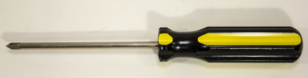
#1 Philips Head Screwdriver [14]
Needle-Nose Pliers (optional)
Book or Box approximately 1 ¼” tall, slightly larger than the top chassis plate
Removable Tape
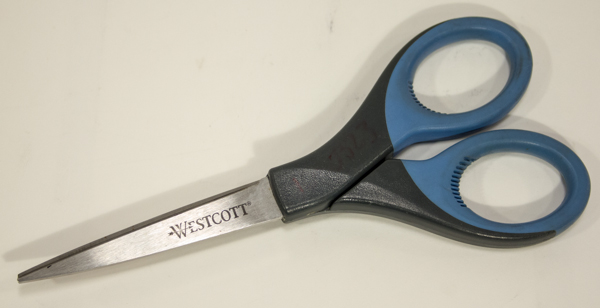
Scissors [15]
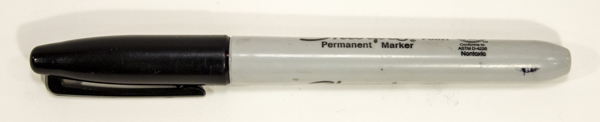
Permanent Marker [16] (or Paint Pen)

http://learn.parallax.com/print/book/export/html/1186[26/09/2017 12:28:19]
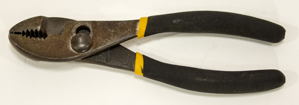
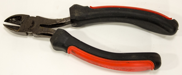
Flat-Nose Pliers
[17]
Diagonal Cutters [18]
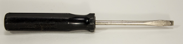
Small Flat-Head Screwdriver [19] (optional)
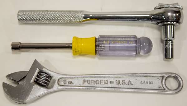
5/16" Wrench, 5/16" Socket, or Adjustable Wrench [20]
Loctite and 242 are trademarks or registered trademarks of Henkel Corporation, U.S.A. Spektrum is a trademark or registered trademark of Horizon
Hobby, Inc. and Bachmann Industries, Inc.
Section 1: Assemble the Booms
In this section, you’ll be assembling the four booms, or "arms" for your ELEV-8 v3.
Warning! As tempting as it may be, DO NOT attach the propellers or propeller
adapters to the motor yet. In fact, you won’t need them until the very last step, so
go ahead and stash them away for the moment.
This section will take approximately 1 to 2 hours, depending on your skill level and equipment.
Tools Needed in this Section
1.5 mm Hex Key (#725-00067, included in Kit)
Paper Towels or other disposable work surface/wipes
#1 Philips Head Screwdriver [14]
Needle-Nose Pliers (optional)
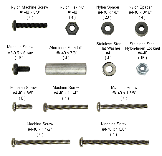
Tip! For your reference, wherever hardware is included in a Parts list, just click on
the item link to open this image [21] in a new window.
Parts Needed in this Section
2 - ELEV-8 v3 Boom - Silver (Clear) (#730-00065), #1 in drawing below
2 - ELEV-8 v3 Boom - Blue (#730-00066), #1 in drawing below
4 – KEDA 1000kV Outrunner Motor (#750-90010), #2 in drawing below
4 – Landing Gear (#721-80007), #3 in drawing below
4 – ELEV-8 v3 Motor Mount (#721-80304), #4 in drawing below
4 - Black Rubber Grommet (#700-00140), #5 in drawing below
4 - Plug, Fits 3/4"OD Tube (#700-00145), #6 in drawing below
8 – Saddle Washer, 3/4" (#712-00010), #7 in drawing below
16 – Machine Screw, M3-0.5 x 6mm [21], #8 in drawing below
4 – Machine Screw, #4-40 x 1 1/2" [21], #9 in drawing below
4 – Machine Screw, #4-40 x 1 1/4” [21], #10 in drawing below
4 - Flat Washer, #4 [21], #11 in drawing below
8 – Locknut, #4-40 [21], #12 in drawing below
8 - Nylon Spacer, #4 x 1/8" Length [21], #13 in drawing below
1 – Loctite® Threadlocker Blue 242® (#700-00106)

http://learn.parallax.com/print/book/export/html/1186[26/09/2017 12:28:19]
A PDF of the above drawing is available for download here [22].
Step 1: Loctite® Motor Set Screws
Apply Loctite® to the motor set screws to prevent them from loosening during flight and potentially causing equipment
failure.
Tools Needed:

http://learn.parallax.com/print/book/export/html/1186[26/09/2017 12:28:19]
Paper Towels or other disposable work surface/wipes
1.5 mm Hex Key
Parts Needed:
4 – KEDA 1000kV Outrunner Motor (#750-90010)
1 – Loctite® Threadlocker Blue 242® (#700-00106)
Instructions:
1. Using the hex key, carefully remove the motor set screw from each motor. The screws may be very tight; be
careful not to break your hex key. If your motors have two set screws, remove only one at a time.
Tip! To open the Loctite® twist off the cap. When you are done, use the other
end of the cap to seal the Loctite®, you'll need it a few more times in the
assembly process.
2. For each motor, apply a small amount of Loctite® to the set screw threads and carefully reinstall the screws. Seat
each screw firmly but do not over-tighten. Work over a paper towel or other disposable work surface for easy
cleanup! If your motors have two set screws, remove and Loctite® the second set screw only after reinstalling the
first one.

http://learn.parallax.com/print/book/export/html/1186[26/09/2017 12:28:19]
3. Allow the Loctite® to set for 10 minutes; it will fully cure in 24 hours.
Step 2: Attach Motors to Motor Mounts
Before the motors can be attached to the Booms, they need to be connected to the Motor Mounts, which are one of the
sacrifical parts of the ELEV-8 v3.
Sacrificial parts are intentionally engineered to fail under excess mechanical stess. They are engineered to fail first, thus
protecting other parts of the system, just as an elecrrical fuse protects an elecrical circuit. In this case, the motor mount is
engineered to to break before the motor is damaged in most (but not all) crashes, since it is less expensive and easier to
replace than the motor.
Tools Needed:
#1 Philips Head Screwdriver
Parts Needed:
4 – KEDA 1000kV Outrunner Motor (#750-900010)
4 – ELEV-8 v3 Motor Mount (#721-80304)
16 – Machine Screw, M3-0.5 x 6mm [21]
Tip! For your reference, wherever hardware is included in a Parts list, just click on
the item link to open this image in a new window.

http://learn.parallax.com/print/book/export/html/1186[26/09/2017 12:28:19]
Instructions:
1. Hold the motor upside-down (the wires come out the bottom of the motor), and place a mount plate over it so that
the holes in the mount line up with those in the motor, and the motor wires come out of the end of the mount. You
may need to flip or rotate your mount around (so it may not match the shown image).

http://learn.parallax.com/print/book/export/html/1186[26/09/2017 12:28:19]
2. Lay the four motor screws out on a paper towel or other disposable work surface. Place a drop of Loctite® on the
threads of each screw.
3. One at a time, insert four screws into the inner-most holes on the motor mount bottom, making sure to line up with
the threaded holes in the bottom of the motor. Tighten with the screwdriver.
4. Repeat this process for the three remaining motors.

http://learn.parallax.com/print/book/export/html/1186[26/09/2017 12:28:19]
Step 3: Feed Motor Wires Through Booms
The extension wires are feed through the booms to protect them, and it's easiest to do so before the motors are mounted.
Grommets are used to protect the wires from the sharp edges of the holes
Tools Needed:
Needle Nose Pliers (optional)
Parts Needed:
4 – Motor/Mount Assemblies from Step 2
2 - ELEV-8 v3 Boom - Silver (Clear Anodized) (#730-00065)
2 - ELEV-8 v3 Boom - Blue (#730-00066)
4 - Black Rubber Grommet (#700-00140)
Instructions:
1. Feed the three cables of one of the motor assemblies through one of the grommets.

http://learn.parallax.com/print/book/export/html/1186[26/09/2017 12:28:19]
2. Slide the grommet all the way to the motor.
3. Feed the three cables of one of the motor assemblies through the large hole on the side of one of the booms,
towards the opposite end of the boom.
4. Pull/push the wires all the way through the boom until they emerge from the other end. You may find needle nose
pliers helpful to pull the wires through.
5. Fit the grommet into the hole.

http://learn.parallax.com/print/book/export/html/1186[26/09/2017 12:28:19]
6. Repeat this for the other three booms.

http://learn.parallax.com/print/book/export/html/1186[26/09/2017 12:28:19]
Step 4: Bolt Motor Mount and Landing Gear to
Booms
Now you will be fastening the motor mounts to the booms and attaching one side of the landing gear.
Tools Needed:
#1 Philips Head Screwdriver
Parallax Combination Wrench (#700-10025)
Parts Needed:
4 – Motor/Mount/Boom Assemblies, prepared in Step 3
4 – Landing Gear (#721-80007)
8 – Saddle Washer, 3/4" (#712-00010)
8– Locknut, #4-40 [21]
4 – Machine Screw, #4-40 x 1 1/2" [21]
4 – Machine Screw, #4-40 x 1 1/4” [21]
8 - Nylon Spacer, #4 x 1/8" Length [21]
4 - Flat Washer, #4 [21]
Note: When determinig which machine screw to use, use the screws with a length
that is equal to or just shorter than the length listed. (Industry standard tolerance for
machine screws allows them to be up to 1/16" shorter than their numerical size.)
Instructions:
1. Feed a #4-40 x 1 1/2” screw through the hole on the motor mount next to to where the wires come out of the motor.
Feed a #4-40 x 1 1/4” screw through the hole on the opposite end of the motor mount.
2. Slide a nylon spacer and saddle washer over the other end of each screw.

http://learn.parallax.com/print/book/export/html/1186[26/09/2017 12:28:19]
3. Insert the screws into the holes on the boom, and feed it through to the other side.
4. Take the short side of the landing gear (see the last image on this page) and feed it over the screw next to the
motor wires, followed by the locknut.
5. Place a washer over the other screw, followed by a locknut.

http://learn.parallax.com/print/book/export/html/1186[26/09/2017 12:28:19]
6. Using the screwdriver and wrench, tighten (clockwise) until there is no longer a gap between any parts (including
nut or screw-head). Then turn the locknut one more full rotation and stop. Do not turn more than this or you may
begin to crush the boom.
7. Repeat for the other three booms.

http://learn.parallax.com/print/book/export/html/1186[26/09/2017 12:28:19]
Step 5: Insert Tube Plugs
In the final step of boom assembly, you'll be fitting plastic caps to the end of the booms, which will help protect them
from impact and gives the ELEV-8 a cleaner look!
Tools Needed:
None
Parts Needed:
4 – Motor/Boom Assemblies, prepared in Step 4
4 - Plug, Fits 3/4"OD Tube (#700-00145)
Instructions:
1. Take a tube plug and orient it such that the lines on the backside are parallel to the axis of the motor. If your plug
looks different, no alignment is
necessary.

http://learn.parallax.com/print/book/export/html/1186[26/09/2017 12:28:19]
2. Push the plug firmly into the end of the boom nearest the motor until it bottoms out.
3. Repeat for the other three booms.
Section 2: Assemble the Chassis
In this section, you will assemble the ELEV-8 v3 Quadcopter chassis, following the four steps below. This section will
take approximately 0.5 to 1.5 hours, depending on your skill level and equipment.
Tools Needed in this Section
Book or Box approximately 1 ¼” tall, slightly larger than the top chassis plate
Removable Tape
#1 Philips Head Screwdriver [14]
Parallax Combination Wrench (#700-10025)
Scissors [15]
Parts Needed in this Section
1 – Top Chassis Plate (#721-80302), #1 in drawing below

http://learn.parallax.com/print/book/export/html/1186[26/09/2017 12:28:19]
1 – Bottom Chassis Plate (#721-80303), #2 in drawing below
4 – Motor/Boom Assemblies from Step 5, #3 & 4 in drawing below
16 – Saddle Washer, 3/4" (#712-00010), #5 in drawing below
16 – Nylon Spacer, #4 x 1/8" Length [21], #6 in drawing below
4 – Machine Screw, #4-40 x 1 3/8" [21], #7 in drawing below
4 – Machine Screw, #4-40 x 1 5/8” [21], #8 in drawing below
8 – Locknut, #4-40 [21], #9 in drawing below
4" – Foam, Adhesive-Backed (#900-00105), not pictured
2 – Hook and Loop Cable Tie (#900-00021), not pictured
A PDF of the above drawing is available for download here [23].
Step 6: Prepare the Top Chassis Plate
Chassis assembly starts with laying out the hardware and placing the top chassis plate upside down on an elevated
surfase, so that the booms can be positioned level in the next step.
Tools Needed:

http://learn.parallax.com/print/book/export/html/1186[26/09/2017 12:28:19]
Book or Box approximately 1 ¼” tall, slightly larger than the top chassis plate
Removable tape
Parts Needed:
1 - Top Chassis Plate (#721-80302)
8 – Saddle Washer, 3/4" (#712-00010)
4 – Machine Screw, #4-40 x 1 3/8" [21]
4 – Machine Screw, #4- 40 x 1 5/8” [21] (or 1 3/4", depending on your kit)
8 - Nylon Spacer, #4 x 1/8" Length [21]
Instructions:
1. Place a small piece of tape under the bottom side of the top plate, underneath the FRONT marking (unless yours is
already marked).
2. Holding the top chassis plate upright with the front toward you, place 1 3/8” screws through the holes indicated by
red circles, and 1 5/8” (or 1 3/4") screws through the holes indicated by blue circles.

http://learn.parallax.com/print/book/export/html/1186[26/09/2017 12:28:19]
3. Place the book or box (shown here as foam) over the plate and hold them together as you flip them over, so that the
top plate is upside-down and the front is now aimed away from you.

http://learn.parallax.com/print/book/export/html/1186[26/09/2017 12:28:19]
4. Slide a nylon spacer over each screw followed by a saddle washer.
Step 7: Connect Booms to Top Chassis Plate
Now you will carefuly lay out the booms to ensure the colors are placed in the corrrect orientation. The clear anodized
(appear silver in color) booms will be at the front, and the blue anodized booms will be at the rear.
Parts Needed:
4 – Motor/Boom Assemblies, prepared inStep 5
1 - Top Chassis Plate, prepared in Step 6
Other manuals for ELEV-8
5
Table of contents
Other Parallax Quadcopter manuals


Popular Quadcopter manuals by other brands


Carrera RC
Carrera RC 370503013X Assembly and operating instructions

Skyrotors
Skyrotors UG470 Quick assembly guide

ScratchBuilds
ScratchBuilds Red Devil Pro v1 quick start guide

Jamara
Jamara Compo AHP 2,4 GHZ Instruction

Reely
Reely Foldable Drone G-Sense operating instructions

Revell Control
Revell Control NAVIGATOR NXT user manual