manuals.online logo
Brands
  1. Home
  2. •
  3. Brands
  4. •
  5. PARASIT STUDIO
  6. •
  7. Recording Equipment
  8. •
  9. PARASIT STUDIO Into the Unknown User manual

PARASIT STUDIO Into the Unknown User manual

INTO THE UNKNOWN
Build Document last updated january 2018
Version 2.1 2017/2018
Into the Unknown Guitar Synthesizer Deluxe is a C OS based fuzz
centered around the CD4046 PLL (phase locked loop) chip and a
CD4015 shift register chip.
It can do brutal fuzz, octave down and octave up, self oscillations,
theremin sounds, flanger'ish modulation and more!
This circuit works best with high output pickups. It is a gated circuit
by nature of the CMOS logic. If you are using single coils and need
more sustain, try a boost or compressor in front. To improve
tracking of the octave down, use your neck pickup with the tone
rolled off.
Happy playing!
Changelog Version 2.1
•The 2.1 version has a different component placement layout
on the PCB (the BO is still the same) for allow for a faster
build.
•ENV output removed
Changelog version 2.0
•The LFO now turns completely off in the middle position to
avoid ticking when not using the LFO.
•LFO gate added (optional). This will make the LFO turn on or
off depending on the input signal. It can be switched in/out
with the board mounted DIP switches.
•Direction of the gate and filter pots are reversed, so that it will
be easier to reset the pedal by turning all knobs counter-
clockwise.
•CV input and ENV output added for future mod possibilites.
ote: The 2.0 PCB is compatible with the old PCB in terms of pots
and switch placement, so it can be a drop in replacement for for
the old board (for anyone that had trouble with ticking).
CON ROLS
KNOBS
IX - Blends between fuzz and octave up. Goes from straight
square wave fuzz to octave up or blend between both. Only the
octave up is affected by the warp, track and LFO.
SUB - Controls the amount of octave down added to the signal.
GATE - Controls the input sensitivity. From very glitchy to gated and
controlled. Turned all the way down (CCW) the circuit will oscillate
by itself. Play around with the track, warp, lfo controls and your
guitar knobs to change the sound and behavoiur of the oscillation
(works best with the pedal directly after your guitar).
RATE - Controls the speed of the LFO. The modulation only affects
the octave up.
LEVEL - Controls the overall output volume.
FILTER - Controls the cutoff frequency of the resonant lowpass
filter. Turn it counter-clockwise to cut out the high end or sweep it
manually up and down for a cool effect.
TRACK - Controls the speed of the octave up tracking.
WARP - I don't know how to discribe this control... It's interactive
with the track control and has a strong effect on the character of
the modulation. Turn up both Track and Warp for Theremin sounds!
SWITCHES
OctD - Toggle between one or two octaves down
OctU - Toggle between one or two octave up
LFO - Triangle wave mode (up), Off (middle) or Square wave mode
(down)
Tweak the knobs and venture Into the Unknown!
General builds tips
•Solder the low profile components first, from short to tall
height. Recommended order: resistors, diodes, IC socket, film-
caps, electrolytics, pots and switches
•C OS chips are very sensitive to static charges and can be
easily damaged. It's a good idea to wear a anti-static
wristband or at least avoid wearing a wool jumper and petting
your cat/dog while building...
•Always use sockets for IC chips and transistors to avoid
heating them directly. It also makes it much easier to swap
them out if needed.
•Pay special attention to the orientation of the diodes and
electrolytics.
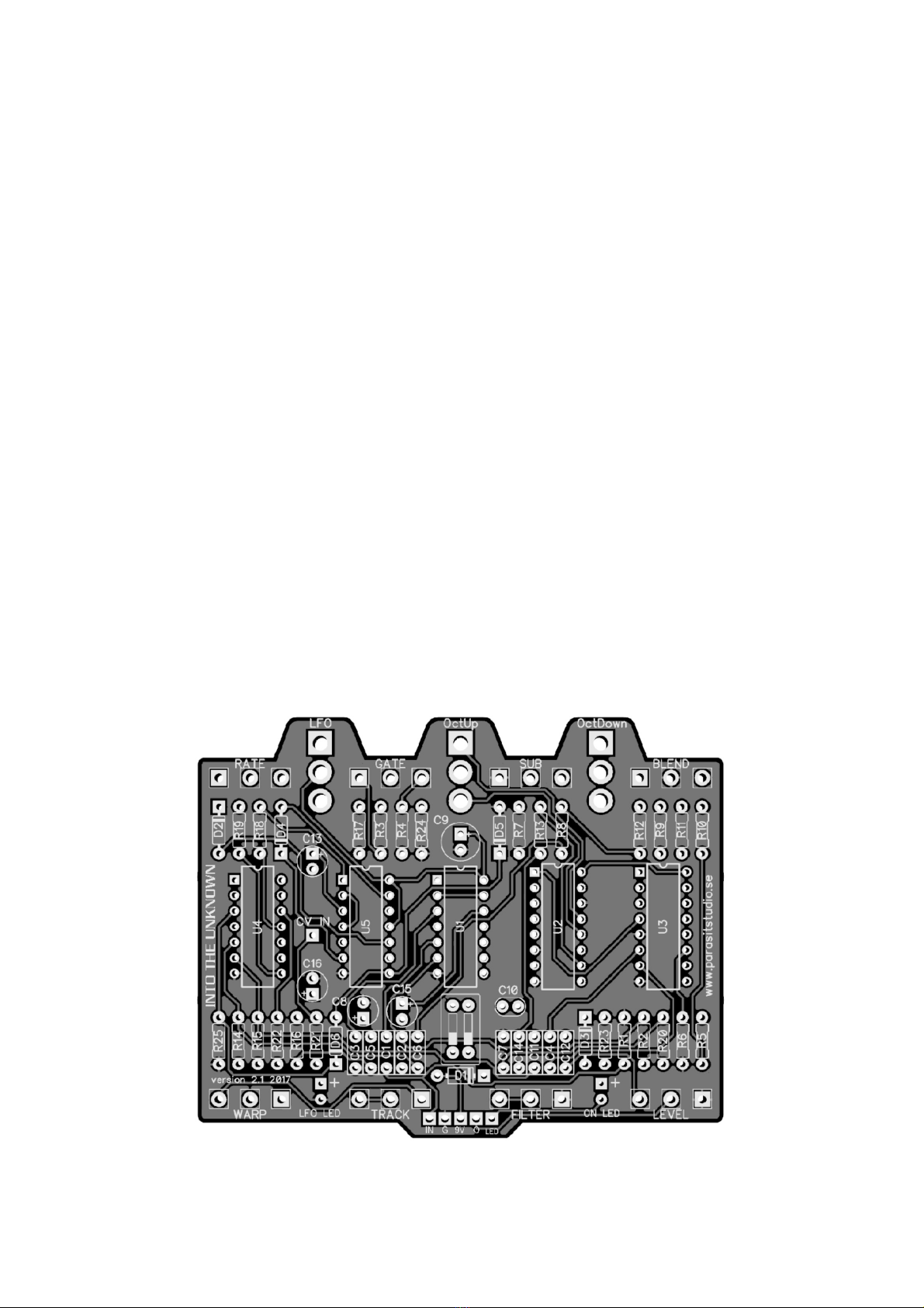
•The square pad represents pin 1 of each pot.
•There are a LOT of switches and pots on this PCB. Be sure to
place them in the PCB without soldering first, THEN place
them in your drilled enclosure. Gently tighten the nuts to the
enclosure, then solder LAST. Otherwise, it will be really hard to
get this in your enclosure.
•This PCB's is designed for 16mm Alpha PCB mounted angeled
pots. You could also use solder lug type and just tack some
“legs” with short pieces of wire to each pot to mimic a PCB
mount type. Again, it is a very good idea to drill holes in your
enclosure first, and mount the pots with the nuts BEFORE
soldering the pots to the PCB. This ensures you won’t put a lot
of stress on the PCB.
•ount the pots, switches and LED's to the back side (solder
side) of the PCB and solder them from the front side
(component side).
Wiring
For more info on how to wire up the stompswitch, jacks ect, please
visit the Parasit Studio website and download the PDF called
”offboard wiring”. You can find it here:
http://www.parasitstudio.se/build-docs.html
Into he Unknown Bill Of Materials (BOM)
•This PCB is designed for two board mounted LED's, one for
bypass indication and one LFO rate indicator.
•* These are current limiting resistors for the LED's. Use the
appropriate value for your LED type.
•The ”LED” hole (next to the output connection hole) should be
connected to the ground for LED bypass on your stompswitch.
Other things not included in the BO but good to have:
enclosure, input and output jacks, DC jack, led bezels, 3PDT
switch and knobs.
Resistors Capacitors IC's
R1 1 C1 100nF IC1 CD4069UBE
R2 1 C2 4.7nF IC2 CD4015BE
R3 2.2 C3 100nF IC3 CD4046BE
R4 1 C4 33nF IC4 CD4069UBE
R5 10K C5 4.7nF U5 CD4066BE
R6 10K C6 100nF
R7 68K C7 100nF Potentiometers
R8 470K C8 2.2uF GATE C250K
R9 100K C9 100uF IX B50K
R10 100K C10 220pF SUB B50K
R11 47K C11 6.8nF RATE C50K
R12 47K C12 100nF FILTER A50K
R13 100K C13 22uF LEVEL A100K
R14 220K C14 2.2nF TRACK A500K
R15 220K C15 2.2uF WARP C10K
R16 10K C16 1uF
R17 470K Diodes Switches
R18 1 D1 1N4001 OctDown SPDT on/on
R19 2.2K D2 1N4148 OctUp SPDT on/on
R20* 4.7K-22K D3 1N4148 LFO SPDT on/off/on
R21 10K D4 1N4148 Optional DIP SWITCH:
R22* 4.7K-22K D5 1N4148 2 positions
R23 100K D6 1N4148 (2 switches, 4 pins)
R24 100K
R25 47K 2x LED's
he LFO gate
The 2.0 version PCB has a LFO gate feature added (similar to the
Arcadiator). It turns the LFO off completely when there is no input
signal, so it stays quiet when not playing. The self oscillation from
turning up the gate pot will also turn on the LFO.
To enable or disable the gate, just turn both dip switches on or off.
If you don't have a DIP switch you can either just link the pads to
have the gate on at all times, or just leave the pads unlinked for a
free running LFO (just like the 1.0 version PCB). I suggest leaving
the pads unlinked unless you are having an issue with ticking. Then
add the links.
Link the upper and lower pads to have the LFO gate engaged at all
times, or just leave it unlinked for a free running LFO.
Drilling template (1590BB)
•This template is approximate. Use at your own risk!
•ake sure your printer isn't doing any scaling / is set to 100%
print size.
•Drill DC jack and input/output jacks to your own preference.
•I measured 20mm from the edge of the enclosure to the
center of the input jack and 37mm from the edge of the
enclosure to the center of the DC jack (on the right side, left
side when your have the enclosure upside down).
•Measure and confirm before drilling!
•Read the build tips section highlighted in red before soldering
pots and switches to the PCB.
roubleshooting
There's always a chance of running into trouble. To minimize error,
follow the BO and general building tips carefully. Take your time
and don't rush. Take a break now and then. Use good solder, and it
helps to have a decent soldering station insted of a cheap iron.
If you are still having trouble, please visit the madbean forum
Parasit Studio subforum section and ask for help there.
http://www.madbeanpedals.com/forum/index.php?board=84.0
If you have bought the usikding kit and have recieved a faulty or
missing component, please contact musikding directly.
https://www.musikding.de/kontakt.php?lang=eng
erms of use
PCB's from Parasit Studio are intended for DIY use only. Commersial resale is
not allowed. It's meant for personal use only, which means that it's not allowed
to build alot of pedals and sell them for profit to strangers using public forums
and craiglist ads. However, it's totally ok to build a few pedals and sell to your
friends and bandmates. After all, that's what this hobby is about. DIY or DIE!
www.parasitstudio.se
[email protected]
Schematic

Other manuals for Into the Unknown

1

This manual suits for next models

1

Popular Recording Equipment manuals by other brands

Rockbox Archos Jukebox Studio 5000 user manual

Rockbox

Rockbox Archos Jukebox Studio 5000 user manual

Danville Signal Processing dspMusik 2/8 user manual

Danville Signal Processing

Danville Signal Processing dspMusik 2/8 user manual

4ms Shaped Dual EnvVCA user manual

4ms

4ms Shaped Dual EnvVCA user manual

Bticino 323008 quick start guide

Bticino

Bticino 323008 quick start guide

BLACK NOISE PIPE user manual

BLACK NOISE

BLACK NOISE PIPE user manual

Digital Voice Systems AMBE-3000 HDK Specifications

Digital Voice Systems

Digital Voice Systems AMBE-3000 HDK Specifications

M-Audio M-Track Eight user guide

M-Audio

M-Audio M-Track Eight user guide

Yamaha MY8-SDI-ED owner's manual

Yamaha

Yamaha MY8-SDI-ED owner's manual

SPEC RSP-501 manual

SPEC

SPEC RSP-501 manual

Champion instruments PRO instructions

Champion instruments

Champion instruments PRO instructions

Mackie HDR 24 user guide

Mackie

Mackie HDR 24 user guide

Akai MPD 24 Operator's manual

Akai

Akai MPD 24 Operator's manual

Car-Interface.com CI-VL2-N902 manual

Car-Interface.com

Car-Interface.com CI-VL2-N902 manual

GRASS VALLEY T user manual

GRASS VALLEY

GRASS VALLEY T user manual

TC Electronic Multi-effects Processor G-Natural user manual

TC Electronic

TC Electronic Multi-effects Processor G-Natural user manual

Pioneer DRM-ULV16 Service manual

Pioneer

Pioneer DRM-ULV16 Service manual

Pioneer CA-X7 operating instructions

Pioneer

Pioneer CA-X7 operating instructions

PAC AP4-CH41 (R.2) manual

PAC

PAC AP4-CH41 (R.2) manual

manuals.online logo
manuals.online logoBrands
  • About & Mission
  • Contact us
  • Privacy Policy
  • Terms and Conditions

Copyright 2025 Manuals.Online. All Rights Reserved.