PARK AUDIO GS Series User manual

TWO-CHANNEL
PROFESSIONAL
POWER AMPLIFIERS
GS4
GS5
GS6
GS7
GS8
GS series
Owner’s Manual
Park Audio

SUPPLY KIT
Power Amplifier 1 pc.
Power Cable 1 pc.
Spare air filter 2 pcs.
Warranty 1 pc.

TABLE OF CONTENTS
Page
Safety Precautions .......................................................................................................................2
General.............................................................................................................................................3
Unpacking .......................................................................................................................................3
Design Features............................................................................................................................4
Functional Features .....................................................................................................................6
Amplifier Block Diagram .............................................................................................................8
Front Panel......................................................................................................................................9
Rear Panel.......................................................................................................................................10
Input and Output Connectors....................................................................................................12
Cabel Requirements ..................................................................................................................14
AC Power Requirements............................................................................................................15
Rack-Mounting Requirements................................................................................................16
Operating Modes .........................................................................................................................17
Maintenance...................................................................................................................................18
Specifications.................................................................................................................................19
Operating Conditions ..................................................................................................................20
Dimensions .....................................................................................................................................21

CAUTION
RISK OF ELECTRIC SHOCK
DO NOT OPEN
AVIS
RISQUE DE CHOC ELECTRIQUE
NE PAS OUVRIR
CAUTION! The GS4, GS5, GS6, GS7,GS8 amplifiers run on 230VAC voltage. Removing
the cover will expose you to a potentially dangerous voltage!
Do not use the unit if the electrical power cord is frayed or broken.
Power is supplied from 230VAC single-phase grounded 50/60 Hz source.
CAUTION! The GS4, GS5, GS6, GS7, GS8 amplifiers can yield dangerous output voltage!
Do not touch the non-insulated cable parts connected to outputs of the unit in operation!
CAUTION! The high sound pressure caused by the high output signal applied to speaker
systems, may endanger your hearing. Please, take care to observe the required safety
precautions.
WARNING SIGNS
Important information! Intended to warn the user about any
important information contained in this Owner’s Manual.
Hazardous voltage inside! Intended to warn the user about electric
shock hazard due to high voltage inside the product.
This sign next to the output terminals warns about dangerous voltage
while in operation.
2

GENERAL
The GS4, GS5, GS6, GS7, GS8 power amplifiers (GS - Series) are designed for sound
signal high-fidelity amplification within professional sound reproduction systems.
The amplifier’s schematics provides for high sound quality whether under low signal
conditions or overload.
WARNING!
Make sure to take all precautions where required.
Please, follow all instructions and guidelines.
To avoid any risk of electrical shock and/or fire hazard, please, do not expose this unit
to rain or moisture. Do not use this unit near open water.
Use dry cloth to clean the unit.
Do not block fan vents.
Do not place the unit near heating radiators, furnaces or other heat-emitting devices.
Do not connect this unit to an ungrounded power supply line.
Protect the power cord against damage.
Disconnect the unit from power supply in case of thunder or during downtime.
In case of malfunctioning, caused by water or any other foreign matter inside or when
the unit has been dropped, or the power cord has been damaged, or the unit has been found
faulty, please, consult qualified personnel.
ATTENTION!
The GS4, GS5, GS6, GS7, GS8 amplifiers have the same design and functional
features and differ only in the schematics elements, output power and weight. Unless
specified otherwise, the word “amplifier” hereinafter applies to any of the above models.
UNPACKING
The manufacturer’s quality control system provides for careful examination of each
product before it leaves the factory to ensure its flawless appearance. After unpacking,
please, check the unit for any physical damage. In case of damage, please, contact your
local dealer. Keep the shipping carton and all packing material, as you may require them for
reshipment of the unit.
3

4
DESIGN FEATURES
Physical Design
The amplifier is enclosed in a metal (steel) case of 2U height. The amplifier is
designed to be installed into a standard 19" rack.
Power Supply Source
Switchable. Individual for each channel.
Cooling System
Forced, cooling rate smooth adjustable system.
Four fans, two per each channel. Backward air flow direction.
Dust Filter
Front panel filter easily removable/replaceable for periodic maintenance.
Power Amplifier Unit
Based on TD Class schematics.
TD Class power amplifier combines the best features of both Class D and analogue
amplifiers. The amplifier boasts the efficiency comparable to Class D amplifiers and
sound quality typical of analogue amplifiers.
Balanced inputs
The use of balanced inputs provides for an essential reduction of the environment-
induced hum and noise interference with long input connecting cables.
Input level Attenuators
Precision ALPS 31-step control knobs, individual for each channel.
Sensitivity slide switches
3 positions: 0.775V, 1.4V or 32dB fixed gain. Individual for each channel.
Mode switch
3-position slide switch.
Operating modes available:
– STEREO – two channels drive two separate loads from two separate signal
sources;
– MONO – two channels drive two separate loads from a single input signal source;
– BRIDGE – two channels drive a common load from a single signal source.
Input filter
Third-order filter individual for each channel.
Two pre-set cutoff frequency points (35Hz and 45Hz ) plus a disable position.

Recommended by world leading manufacturers of loudspeakers.
This filter cuts off any signals below 35Hz or 45 Hz which generally cannot be
reproduced by most professional loudspeakers.
The filter significantly reduces the displacement of the LF speaker cone below the
loudspeaker frequency cut-off point which makes it possible to increase the power applied to
the LF speaker (the power being not wasted for the cone “flapping”) and thus to raise the
sound pressure created by the loudspeaker without any danger of overheating the LF drivers
. When it is necessary to achieve a linear frequency response to drive full-range
loudspeakers generally used in studios or in cinema theaters, the input filter can be disabled
(bypassed for each channel individually) with the slide switches located on the amplifier rear
panel.
See below the amplifier low frequency response diagrams.
Optoelectronic Clip-Limiter
Independent for each channel.
Reduces the level of the input signal and eliminates the distortion, caused by hard clipping.
Removable Power Cord
A powerCON 20A NEUTRIK connector for GS4, GS5 and a powerCON 32A
NEUTRIK connector for GS6, GS7, GS8.
This feature is provided for convenience of transportation and rack mounting.
20Hz 50Hz 100Hz 200Hz 900Hz
-10
-5
0
5
10
«45 Гц»
20Hz 50Hz 100Hz 200Hz 900Hz
-10
-5
0
5
10
«OFF»
20Hz 50Hz 100Hz 200Hz 900Hz
-10
-5
0
5
10
«35 Гц»
5

6
FUNCTIONAL FEATURES
Output Short-Circuit Protection
Individual per each channel. Protects the output stage of the power amplifier against
short-circuiting, as well as limits the output current when a maximum-level sine signal is
applied continuously to 2-Ohms loudspeaker.
Overload Protection
The double-stage overload protection system, independent for each channel, protects
the output stage and optimizes the quality sound under overload.
In the event of short overloads (for example, caused by a sharp decrease in the
complex load resistance), only the current protection of the output stage is activated. It
limits the output transistors current to safe level. Protect threshold allows to give full
output power shortly, even on case of very low load.
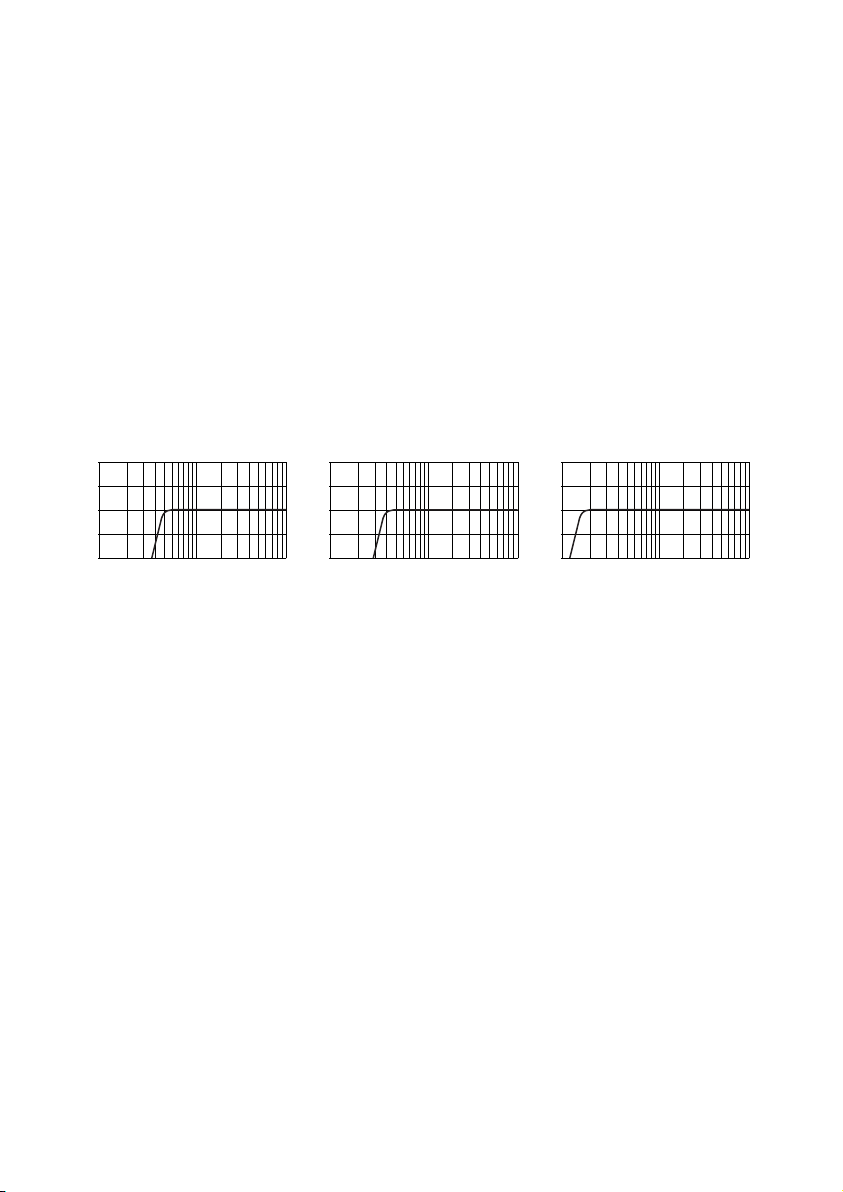
In case of a more continuous overload, the protection system activates the built-in
Clip-limiter, which reduces the level of the input signal.
DC Output Protection
Independent for each channel. Prevents DC damage to loudspeakers.
The amplifier’s schematics precludes transit of any clicks or noise during the
power-on/off transition process.
Protection of loudspeakers against DC damage is ensured for each channel by
individual power supply units which are disabled in the event of output DC voltage or
any powerful LF fluctuations. In case the protection system becomes active on both
channels and both power supply units become disabled, all indicators go off.
The amplifier can be restarted with the POWER toggle switch, by way of turning
the amplifier off and turning it on, about 2 minutes later again.
High Frequency Protection
Independent for each channel. Prevents any damage to HF drivers as might be caused
by non-musical signals of powerful high frequency spectrum.
Should any powerful high frequency fluctuations occur on the output either as a
result of poor contact in the input cable connectors, or being send to the amplifier’s
input by any other device (such as a crossover or mixing console), the protection
system activates the built-in optoelectronic Clip-limiter to reduce the input signal level.
Thus the protection system effectively prevents any damage to tweeters as might be
caused by non-musical signals of powerful high frequency spectrum.
Thermal Protection
Independent for each channel. Protects the amplifier’s output stage against
overheating.
The amplifier may stop functioning only in case of the fan breakdown or blocked
air flow. In this case upon reaching 85°С, the independent protection system disables
the respective channel of the amplifier. The CLIP LED goes on and the SIGNAL LED of
the affected channel goes off. The amplifier resumes its operation in the reverse order.
As soon as the amplifier cools down, the affected channels gradually regain their
amplification level up to the set value.

7
Soft Start
Reduces the power-on inrush current.
The soft start system is provided to reduce inrush current to the amplifier and
to minimize the noise contributed by the amplifier to the power mains during the
power-on process.
Soft Signal Start
Ensures smooth power-on sound signal rise.
During the power-on process, this feature ensures smooth gain from zero to
the maximum level to provide for a smooth rise of the sound level emitted from the
loudspeakers.
Overvoltage Protection System
Relay system. Used to protect the amplifier against overvoltage in the mains.
In case of accidental connection of the amplifier to incorrect-wired mains, the
inter-phase voltage of 400V may be applied to the amplifier. In this case the
protection system will block the mains connection to the power supply. Only the
protection system stand-by power supply unit remains in operation. The system
activates, whenever the mains voltage exceeds ~265V. The amplifier automatically
resumes operation after the mains voltage goes down to ~260V.

8
AMPLIFIER BLOCK DIAGRAM
1+
2+
CH 1
INPUT
THRU
1+
2+
OUTPUT
CH 1, CH 2,
BRIDGE
+U
OUTPUT
CH 2
CH 2
INPUT
THRU
Power
amplifier
Power
amplifier
Class D
Class D
_U
+U
_U
Class D
Class D
MONO
MODE
LEVEL
Clip
Limiter
0.775V
GAIN
45 Hz
HI PASS
FILTER
35Hz
45Hz
35 Hz
OFF
1.4V
32 dB
45Hz
LEVEL
0.775V
GAIN
45 Hz
HI PASS
FILTER
35Hz
45Hz
35 Hz
OFF
1.4V
32 dB
45Hz
STEREO
BRIDGE
Clip
Limiter

FRONT PANEL
THERM LEDs – thermal protection indicators.
ALARM LEDs – DC output or powerful LF fluctuation alarm condition*.
CLIP LEDs – overload indicators.
POWER LED.
Dust filters.
LEVEL– input signal attenuators**.
LEDs – indicate the signal level (dB) at the amplifier output.
POWER switch.
Notes:* Upon power-on, the LEDs go on for a while. This is normal.
** Input level Attenuators dB attenuation 31-step control knobs .
WARNING! The above knobs adjust the sensitivity level rather than the amplifier output
power.
43 5
CLIP
ALARM
POWER
CLIP
9
6
20
3
ALARM
CH 1CH 2
0
THERM THERM
15
LEVEL
9
6
20
3
0
15
LEVEL
GS 8
P RO FE SS I ON AL P OW E R AM PL I FI ER
Pa rk Audi o
21 6
7
dB dB
dB
T0
dB
1
10
40 4
6
8
12
1416
18
22
28
32
50
dB
T0
dB
1
10
40 4
6
8
12
1416
18
22
28
32
50
11 9 8 814 13 10
12
1
26
35
4
8 14
9 13
10 12
11
9
7

10
REAR PANEL
GS4, GS5
INPUT
CH2
CH 1
CAUTION
RISK OF ELECTRIC SHOCK
DO NOT OPEN
NE PAS OUVRIR
RISQUE DE CHOC ELECTIQUE
AVIS
Use INPUT CH1 for MONO & BRIDGE MODE
TO REDUCE THE RISK OF FIRE OR ELECTRIC SHOCK
DO NOT EXPOSE THIS EQUIPMENTTO RAIN OR MOISTURE.
DO NOT REMOVE COVER.
NO USER SERVICEABLE PARTS INSIDE.
REFER SERVICING TO QUALIFIED SERVICE PERSONNEL.
WARNING
MODE
MONO
STEREO
BRIDGE
THRU
INPUT
THRU
PUSHPUSH
CH1
CH2
2 min
BRIDGE
2 min
4 min
2 min
CH2
SPEAKER OUTPUTS
1
1 1
1 1 2
2
2
1
MAINS IN
~230V AC
CAUTION
DO NOT BLOCK FAN VENTS
THE UNIT HAS COOLING
Pa rk Aud io
45Hz
35Hz 45Hz
35Hz
31 754 62
12
8 9
11
1314
10
15
INPUT
CH2
CH 1
CAUTION
RISK OF ELECTRIC SHOCK
DO NOT OPEN
NE PAS OUVRIR
RISQUE DE CHOC ELECTIQUE
AVIS
Use INPUT CH1 for MONO & BRIDGE MODE
TO REDUCE THE RISK OF FIRE OR ELECTRIC SHOCK
DO NOT EXPOSE THIS EQUIPMENTTO RAIN OR MOISTURE.
DO NOT REMOVE COVER.
NO USER SERVICEABLE PARTS INSIDE.
REFER SERVICING TO QUALIFIED SERVICE PERSONNEL.
WARNING
MODE
MONO
STEREO
BRIDGE
THRU
INPUT
THRU
PUSHPUSH
CH1
CH2
2 min
BRIDGE
2 min
4 min
2 min
CH2
SPEAKER OUTPUTS
1
1 1
1 1 2
2
2
1
NLT4M
L
I
N
E
I
C
E
H
T
T
E
N
S
NLT4M
L
I
N
E
I
C
E
H
T
T
E
N
S
MAINS IN
~230V AC
CAUTION
DO NOT BLOCK FAN VENTS
THE UNIT HAS COOLING
Pa rk Aud io
45Hz
35Hz 45Hz
35Hz
31 754 62
12
8 9
11
1314
10
15
GS6, GS7, GS8
THRU – line outputs (XLR male).
Used to deliver input signal to the input of another amplifier. THROUGH connectors
are parallel to INPUT connectors of respective channels.
GAIN – input sensitivity.
Used to select the input sensitivity (0.775V, 1.4V) or a 32dB fixed gain.
INPUT – Channel 2 balanced input (XLR female).
HI PASS FILTER – cutoff filter switches.
Used to set the required cutoff frequency (35Hz or 45Hz) or to disable the filter (See:
Input Filter).
MODE switch:
– MONO – two channels drive two separate loads from a single input signal source;
– STEREO – two channels drive two separate loads from two separate input signal
sources;
– BRIDGE – two channels drive a common load from a single input signal source.
19
28
3
46
5

11
INPUT– Channel 1 balanced input (XLR female).
Used to supply input signal to channel 1, channel 1 and 2 (in MONO mode), and a
common input signal (in BRIDGE mode).
Label.
Contains the amplifier model designation, power ratings and Serial No.
Air vents
MAINS IN – power cord socket (powerCon) for 230V AC 50/60Hz grounded mains.
Channel 1/2/ bridge output, used either to connect a load (loudspeaker) to Channel1,
or to connect it to both channels, with a single SPEAKON connector, as well as to
connect a load (loudspeaker) to the amplifier in BRIDGE Mode.
Channel 2 output
Used to connect a load (loudspeaker) to Channel 2.
11
10
7
15
12
13
14

12
INPUT AND OUTPUT CONNECTORS
Input Connectors
Use XLR (male) connectors to connect to the amplifier inputs and XLR (female)
connectors to line outputs.
21
3
2 1
3
XLR male XLR female
Cold « – »
Shield (Ground)
Hot « + »
Cold « – »
Hot « + »
Shield (Ground)
Output Connectors
To connect loudspeakers to the amplifier outputs, use SPEAKON NL2FX connectors.
Use a SPEAKON NL4FX or NLT4FX connector for bridged connection or for connection of
both channels with a single cable.
The SPEAKON NL2FC or NL4FC connectors may be used to connect loudspeakers
to the outputs of GS4 or GS5 amplifiers.
Wiring for Loudspeakers Connection at STEREO and MONO MODE
NL2FX
Output (–)
NL4FX
1+
1- 1+
1-
Output ( )
+Output (–) Output ( )
+
Wiring for Loudspeakers Connection at BRIDGE MODE
NL4FX
2+ 2-
1+
1-
Output (–)
Output ( )
+

13
Wiring for Loudspeakers Connection for connecting two channels
with a single connector
Use a POZIDRIVE PZ1 screwdriver to connect cables to connectors. Never use a
PHILIPS screwdriver. See the detailed wiring information at http://www.neutrik.com
CAUTION! Never attempt to jumper or otherwise link up any pins of output connectors.
NL4FX
2+ 2-
1+
1-
Channel 2
Output (+)
Channel 1
Output (+)
Channel 1
Output (–)
Channel 2
Output (–)

14
CABLE REQUIREMENTS
Input Cables
Make sure to use only shielded cables whether balanced or unbalanced. Shielding
when properly grounded protects a signal against external electrical interference. As a rule,
unbalanced lines of over 3 meters long are not acceptable. Greater distances require a
balanced cable.
Avoid placing input cables close to power cords or power transformers.
Output Cables
The amplifier is capable of delivering high level output current; therefore, the wire
gauge used for speaker cables is particularly important. Inadequate wire gauge adds
significant resistance to the speaker’s own impedance, reducing the power which is actually
delivered to the speaker. It will also result in a decreased damping factor and possible fire
hazard.
Since the power applied to the loudspeaker is of primary concern in system design, we
have included the table below to allow you determine the appropriate wire gauge for your
application.
Power Loss in a 10-meter Cable
1.50
2.00
2.50
4.00
6.00
0.24
0.18
0.15
0.09
0.06
10.7 %
8.3 %
7 %
4.3 %
2.9 %
2.9 %
2.2 %
1.8 %
1.1 %
0.7 %
5.7 %
4.3 %
3.6 %
2.3 %
1.5 %
Wire Gauge
2
(mm )
Cable
Resistance
(Ohms)
Cable power loss
2Ohm load 8Ohm load4Ohm load
The table shows the percentage of the power loss in a 10-meter copper multiple-core
cable. This table reflects the power loss as a percentage of the output power of the amplifier
applied to the load. Use this table to determine the power loss to the load at other cable
lengths. For example, if you plan to deliver 1000Watts to 2-Ohms load through 20m of 2.5-
mm2 cable, the power loss in the cable would be 7 % x 2=14 % of 1000W or 140W lost in the
cable.

AC POWER REQUIREMENTS
Use 230 V 50/60 Hz single-phase grounded power supply mains for amplifier.
The quality of the AC power supply mains is of prime importance for the
amplifier functioning. The amplifier should be powered from the mains designed
for at least 1.5 times the average current consumed by the amplifier.
Never try to connect the amplifier to a household power supply mains.
Use the power cord supplied. The power cord supplied with a GS6, GS7 or GS8
amplifier has only a PowerCon connector on one side. The other side of the cord should
be connected either directly to the power distributor terminal box or to an industrial-type
three-pin plug. Use a plug designed for the current rating not less than the average
current consumed by the amplifier.
Connection and wiring must be performed by a qualified technician.
Never use household-type electric plugs.
Prior to plugging, please, make sure that there are no other devices consuming
much AC current, as the normal operation of such several devices may be impossible.
In the event of line voltage sag, the unit will continue to operate normally, albeit with less
power.
The actual AC current consumption by the amplifier depends on the type of the
music program and the load impedance. While installing the audio systems, in order to
optimize the power wiring, please, note that for reproduction of typical audio material at
the full output level, the average current consumption rate is as follows:
– 4/7 A for GS4 into 4/2 Ohms;
– 5/9 A for GS5 into 4/2Ohms;
– 6/11 A for GS6 into 4/2 Ohms;
– 7/11 A for GS7 into 4/2 Ohms;
– 8 A for GS8 into 4Ohms.
* Note: The above ratings are given for a crest-factor 3 musical signal. Some
modern music genres may have less crest factor, which may lead to increased current
consumption.
In order to minimize the AC current hum and noise, make sure to plug all audio
devices interconnected with signal cables, into the same mains outlet.
15

16
RACK-MOUNTING REQUIREMENTS
The amplifier is designed to fit a standard 19” rack. While mounting, make sure to
provide unhindered air access to the front and rear sides of the rack. The fan blows air
backwards. It is not necessary to leave empty space above or below the amplifier. Prior to
installing the amplifier into the rack, remove the rubber feet from the amplifier bottom panel.
Having done that, put the amplifier into the rack and secure it in place with four screws with
washers. The manufacturer strongly recommends to secure the amplifier rear brackets to
the rack, too. Where required, use a transition bracket (optional) to extend the mounting
depth of the amplifier mounted into the rack.

17
OPERATING MODES
STEREO Mode
Two input signals are linked up to the input connectors of respective channels.
Speakers are linked up to the output of respective channels. See the connector wiring
in the Loudspeaker Connector Wiring Section.
MODE switch is set to STEREO.
For most applications, it is recommended to set the input HI PASS FILTER switches to
45Hz or 35Hz (depending on the specific application and/or loudspeaker ratings). However,
when it is necessary to obtain a linear frequency response to drive full-range loudspeakers,
as in studios or cinema houses, set this input filter switch to OFF. See the Input Filter
Section.
To adjust the level of input signal, use a LEVEL control of each channel.
MONO Mode
Input signal is linked up to Channel 1 input connector.
Speakers are linked up to the output of respective channels. See the connector wiring
in the Loudspeaker Connector Wiring Section.
MODE switch is set to MONO.
For most applications, it is recommended to set the input HI PASS FILTER switches to
45Hz or 35Hz (depending on the specific application and/or loudspeaker ratings). However,
when it is necessary to obtain a linear frequency response to drive full-range loudspeakers,
as in studios or cinema houses, set this input filter switch to OFF. See the Input Filter Section.
To adjust the level of input signal, use a LEVEL control of each channel.
BRIDGE Mode
Input signal is linked up to Channel 1 input connector.
Speaker is linked up to Channel 1 output.
See the connector wiring in the Loudspeaker Connector Wiring Section.
MODE switch is set to BRIDGE.
WARNING! The GAIN sensitivity switches, located on the rear panel, must be
always set to the same position on both channels.
For most applications, it is recommended to set the input HI PASS FILTER switches to
45Hz or 35Hz (depending on the specific application and/or loudspeaker ratings). However,
when it is necessary to obtain a linear frequency response to drive full-range loudspeakers,
as in studios or cinema houses, set this input filter switch to OFF. See the Input Filter
Section.
Use channel 1 LEVEL control to adjust the level of the input signal.
* Note: In this mode, only Channel 1 switch is active.

18
MAINTENANCE
Cleaning of Dust Protective Air Filter
No special tools are required for removing the filter. Just grip it and pull. Wash the filter
with any detergent, flush it with water, let it dry and re-install.
In case the filter is worn out, replace the filter with a spare one supplied.
ATTENTION! Never install a wet filter.
Do not dry the filter with hot air or expose it to direct sun rays.
Other manuals for GS Series
1
This manual suits for next models
5
Table of contents
Other PARK AUDIO Amplifier manuals

PARK AUDIO
PARK AUDIO df1404 mkII User manual

PARK AUDIO
PARK AUDIO DF DSP Series User manual

PARK AUDIO
PARK AUDIO DF-SERIES WITH DSP User manual

PARK AUDIO
PARK AUDIO GS Series User manual

PARK AUDIO
PARK AUDIO TA Series User manual

PARK AUDIO
PARK AUDIO RX Series User manual

PARK AUDIO
PARK AUDIO DX1000T DSP User manual