Parker PAC-96-24 User manual

CLICK TO CHANGE TEXT
1
AIR COMPRESSOR
EN
OWNERS MANUAL
PAC-96-24 / PAC-96-50

3
GENERAL SAFETY RULES ................................................................................................ 4-5
SAFETY SYMBOLS .................................................................................................................. 6-7
FOR SAFE OPERATION ........................................................................................................ 8-12
WHAT'S IN THE BOX? ........................................................................................................... 14-15
PRODUCT FEATURES ........................................................................................................... 16-17
ASSEMBLY ..................................................................................................................................... 18-20
PRE-OPERATION ...................................................................................................................... 21
OPERATION .................................................................................................................................. 22-26
MAINTENANCE .......................................................................................................................... 28-32
TROUBLESHOOTING ............................................................................................................ 34-35
EXPLODED DIAGRAM .......................................................................................................... 36
PARTS INDEX .............................................................................................................................. 37
SPECIFICATIONS ...................................................................................................................... 38
GUARANTEE ................................................................................................................................ 39
DECLARATION OF CONFORMITY ............................................................................. 41
2
INTRODUCTION CONTENTS
This manual has been produced by Parker Products Ltd. and should be kept with the product and referenced
for operation, maintenance and troubleshooting.
This manual contains an overall description of the product, together with all the necessary information for using the
product correctly and safely. It is highly recommended that this manual is read prior to any operation or maintenance of
this product. The safety precautions and warnings are to ensure your safety and protect you from harm or damage to
the product.
All photographs and drawings in this manual are supplied by Parker Products Ltd. to help you with the operation and
maintenance of the product. The information contained in this manual was accurate at the time of production, however
Parker Products Ltd. may make modifications to the product without notification. This Air Compressor has been designed
for personal and private use only.
The product is to be used only for its prescribed purpose, any other use is deemed to be a case of misuse.
The user/operator and not the manufacturer will be liable for any damage or injuries of any kind caused as a result of this.
Please note that our equipment has not been designed for use in commercial, trade or industrial applications.
Our warranty will be voided if the machine is used in commercial, trade or industrial businesses or for equivalent purposes.

4 5
• READ THIS MANUAL CAREFULLY BEFORE USING THIS MACHINE.
• WARNING! Never allow children or anyone who does not fully understand the directions given in the manual to use the machine.
• ALWAYS USE safety equipment; appropriate footwear, eye protection, ear protection, head protection, trousers and gloves.
• NEVER use the product when ground is slippery, at night, during rain storms, lightning storms, or at times of strong wind.
• NEVER operate this machine when you are fatigued, ill or under the influence of alcohol, drugs or medication.
• NEVER perform maintenance or assembly procedures on this machine when the machine is running.
• NEVER unscrew any connecting parts while the tank is still under pressure.
• NEVER disassemble any electrical parts before disconnecting the electrical plug.
• ALWAYS use caution when adjusting the safety valve.
• NEVER use the compressor when the voltage is too low or too high.
• NEVER use electrical cable more than 5m long with less 2 than a 1.5 mm section rated to 16A.
• NEVER disconnect the plug to stop the compressor, turn the switch to the OFF position.
• CAUTION! If the release valve does not work when the motor is stopped find the cause immediately to prevent damage to the motor.
• CAUTION! When restarting with the reset button check the compressor for problems and check the pressure in the tank is under
0.8Mpa.
• ALWAYS Disconnect the plug to cut o the power supply and open the outlet valve and discharge all the air in the air tank after use.
• CAUTION! For your protection, if this tool is to be used outdoors, it should not be exposed to rain, or used in damp locations.
• CAUTION! Never use this machine if it has been damaged of is in need of replacement parts.
• INSPECT the entire unit for loose fasteners and fittings.
• WATCH OUT for children, pets, open windows etc and blow debris safely away.
• ALWAYS shut o the machine whilst not in use.
• ALL MAINTENANCE other than that listed in this manual should be carried out by professionally trained and certified personnel.
GENERAL SAFETY GENERAL SAFETY
WARNING
To reduce the risk of injury, user must read
instruction manual.
GLOVES
Gloves should be worn where appropriate.
HEAD, EYE & EAR PROTECTION
Approved head, eye & ear protection should be
worn at all times during operation.
BOOTS
Wear sturdy, non-slip boots.
CLOTHING
Appropriate clothing should be worn during
operation. Ensure clothing is made of strong
fabric and is not baggy or loose.
RESPIRATOR
Protect your lungs against dust.
ON
OFF
For safe operation and maintenance symbols are moulded in relief on the machine or shown on a label.

6 7
SAFETY SYMBOLS
SAFETY SYMBOLS
WARNING! To reduce the risk of injury,
user must read instruction manual.
This symbol, before a safety comment, indicates a
PRECAUTION, a WARNING or a DANGER. Ignoring
this warning can lead to an accident for yourself or for
others. To limit the risk of injury, fire, or electrocution
always apply the recommendations indicated.
RISK OF INJURY. DO NOT OPEN OR
REMOVE SAFETY SHIELDS WHILE
ENGINE IS RUNNING.
DO NOT TOUCH THE MOVING PARTS OF
THE MACHINE UNTIL THEY ARE
COMPLETELY STOPPED.
WARNING! Never to touch the spark plug or plug
cord while the machine is in operation. Doing
so may result in being subjected to an electrical
shock.
WASTE ELECTRICAL PRODUCTS SHOULD NOT BE
DISPOSED OF WITH HOUSEHOLD WASTE. PLEASE
RECYCLE WHERE FACILITIES EXIST CHECK YOUR
LOCAL AUTHORITY OR RETAILER FOR RECYCLING
ADVICE
CONFORMS TO CURRENT SAFETY STANDARDS
Triman - Waste Collection & Recycling
Double Insulated
RISK OF ELECTRIC SHOCK.
The compressor must be disconnected from the mains
supply before removing any covers. Do not use in a
damp environment.
HOT SURFACES.
This compressor contains surfaces which may reach a
high temperature during operation. Never operate with
the motor housing removed.
RISK OF ACCIDENTAL START-UP.
The compressor could start automatically in the event
of a power cut and subsequent reset. Do not carry the
compressor while it is connected to the power source,
or when the tank is filled with compressed air.
EXTREME PRESSURE.
Servicing while pressurised can cause severe injury.
Turn o machine and release pressure before
attempting to service.
Air and condensation water can burst from the
compressor when the drain plug is removed.

8 9
WARNING! - As with all machinery, there are certain hazards involved
with their operation and use. Exercising respect and caution will
considerably lessen the risk of personal injury. However, if normal safety
precautions are overlooked, or ignored, personal injury to the operator, or
damage to property may result. It is in your own interest to read and pay
attention to the following rules:
WARNING! - When using the air compressor, you should follow basic
safety precautions including the following to reduce the risk of personal
injury. Make sure that you have read all of the instructions before using
the air compressor. Keep this booklet with the compressor for future
reference by the operator. Persons who have not read this booklet should
not use the air compressor.
WARNING! - Compressed air can be dangerous. Death or serious injury
could result from improper or unsafe use of this compressor. To avoid
these risks, use your common sense and follow these basic safety
instructions. Compressed air should never be inhaled as it may contain
toxic vapours or solid particles. Always work in good ventilation,
especially when spraying paints or other toxic substances and always
use a suitable face mask. Do not spray near sources of possible ignition.
WARNING! - Attachments, hoses and accessories must meet or exceed
the maximum pressure rating of this compressor. If low pressure parts
are used, the air pressure could cause them to explode or fly apart,
resulting in serious injury. Always take great care when releasing the
pressure and connecting/disconnecting tools.
WARNING! - This compressor must be connected to a power socket that
is safeguarded by a suitable circuit breaker or fuse.
TRAINING: Prior to use all operators should become familiar with the
instructions in this booklet. In particular, become familiar with the ON/
OFF control for emergency stopping.
ALWAYS USE EYE PROTECTION: When operating the air compressor,
always use eye protection, and make sure that other people in the work
area are also using eye protection. Eye protectors must provide
protection from flying particles both from the front and from the side.
NEVER TOUCH MOVING PARTS: Never place your hand near any
moving parts on the air compressor or operate with the covers removed.
PROTECT YOUR SELF AGAINST ELECTRIC SHOCK: Never operate the
air compressor in wet or damp locations.
DRESS PROPERLY: Loose clothing or jewellery may be caught in
moving parts. Always tie long hair back.
KEEP VISITORS/CHILDREN AWAY: Do not allow visitors/children to
handle the air compressor or attachments and ensure that any people in
the work area are suitably dressed.
KEEP THE WORK AREA CLEAN: Cluttered areas invite accidents, clear
the work area of all unnecessary tools, debris and furniture.
DISCONNECT THE AIR COMPRESSOR: Always disconnect the air
compressor from the mains power supply and decompress before
performing maintenance, changing any parts and when not in use.
DO NOT ABUSE THE CABLE: Never pull on the cable when removing
the plug from the mains socket, or lift the compressor by the mains cable.
BREATHING QUALITY AIR: This compressor should not be used to
supply breathing quality air.
DO NOT ABUSE THE COMPRESSOR: Do not stand on the compressor.
SAFETY VALVE: Never remove or attempt to adjust the safety valve.
Keep the safety valve free from paint and other accumulations.
AVOID UNINTENTIONAL STARTING: Do not move the air compressor
when it is connected to the mains power supply. When connecting the
air compressor to the mains supply make sure the red button on top of
the air compressor is in the OFF (down) position.
FOR SAFE OPERATION
FOR SAFE OPERATION
i
i
i
i
i
i
i
i
i
i
i
i
i

10 11
KEEP ALL SCREWS AND COVERS TIGHTLY IN PLACE: Check the
screws and covers periodically.
ADEQUATE VENTILATION: The compressor should only be used in
areas with adequate ventilation and should not be exposed to heat, or
used near inflammable substances.
NEVER USE AN AIR COMPRESSOR WHICH APPEARS DEFECTIVE
OR IS OPERATING ABNORMALLY: If the compressor operates
unusually or makes strange noises, switch o immediately and purge the
air tank. Arrange repair with an authorised service centre.
DO NOT MODIFY THE AIR COMPRESSOR: Do not attempt to modify
the air compressor, tank, fittings or attachments in any way. Doing so will
invalidate the guarantee and could result in personal injury.
DO NOT MODIFY THE TANK: Do not modify the tank or operate at
pressures or temperatures outside the limits stated in this booklet.
TURN OFF THE AIR COMPRESSOR WHEN NOT IN USE: When not in
use, turn o the air compressor by pressing the On/O switch, remove
the plug from the mains supply and slowly undo the drain valve to release
the pressure from the tank. Remember to close the drain valve before
storage and ensure it is fully tightened before use.
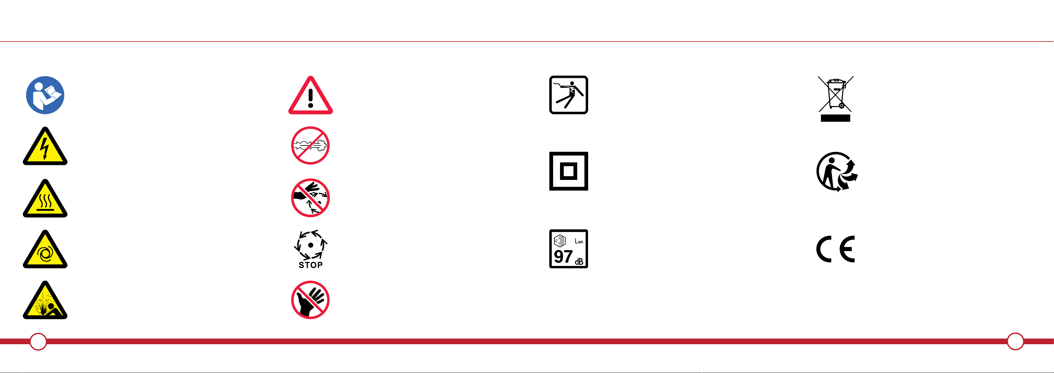
DO NOT TOUCH HOT SURFACES: During operation, the motor,
connections, compressor body, cylinder head and tubes may get hot,
please take care.
DO NOT DIRECT THE AIR STREAM AT THE BODY: Do not direct the
air stream at people or animals, as injury may result. Compressed air
can cause soft tissue damage and propel dirt and other particles at high
speed.
ONLY USE RECOMMENDED PARTS: To avoid the risk of bursting, only
hoses with a rated pressure of 8 bar, or more should be used. Never
attempt to repair faulty hoses.
DO NOT USE THIS COMPRESSOR TO INFLATE SMALL,
LOW-PRESSURE OBJECTS: Items such as children's toys or footballs
can explode if over-inflated.
AVOID KINKING OR TRAPPING THE AIR HOSE: Always replace faulty
hoses - never attempt a repair if a leak is detected.
DRAIN TANK: Drain the tank after each use, switch o and slowly open
the drain valve to release the air then tilt the compressor to empty
condensed water
STORE THE AIR COMPRESSOR PROPERLY: When not in use the air
compressor should be stored in a secure, dry place out of the reach of
children. Always lock up the storage area.
PROTECT YOUR HEARING: Ear protection should be worn when
operating this compressor.
MAINTAIN THE AIR COMPRESSOR WITH CARE: If the air compressor
is damaged in any way, have it repaired by a qualified service engineer.
EXTENSION LEAD: Only use extension leads that are of an
appropriate power rating and suitable for the work environment.
Extension leads must have an earth connection. Inspect the extension
lead regularly and replace if damaged.
ONLY USE PARTS AND ACCESSORIES RECOMMENDED IN THIS
MANUAL: The use of unauthorised accessories or attachments is not
permitted and may result in personal injury and damage to the air
compressor. Do not attempt to repair or modify the air compressor.
STAY ALERT: Watch what you are doing, use common sense, and do
not operate the air compressor when you are tired. The air compressor
should not be used if you are under the influence of alcohol, drugs or any
medication that makes you drowsy.
EACH USE CHECK THE AIR COMPRESSOR AND HOSE FOR
DAMAGED PARTS: Never use the air compressor if it has been
damaged in any way. Have the air compressor repaired by a qualified
service engineer. Do not use the air compressor if the On/O switch does
not operate correctly.
HANDLE THE AIR COMPRESSOR CAREFULLY: Operate the air
compressor according to the instructions contained within this
instruction booklet. This air compressor should never be operated by
children or individuals unfamiliar with its operation.
KEEP THE MOTOR AIR VENT CLEAR: Keep the motor vent clear and
free from dust, wipe regularly to maintain an adequate supply of clean air
to the air compressor.
OPERATE THE AIR COMPRESSOR AT THE CORRECT VOLTAGE: Make
sure that the mains supply voltage is the same as the voltage shown on
the rating plate.
DO NOT WIPE THE PLASTIC PARTS WITH SOLVENT: Do not use
solvents or thinners such as petrol, benzene, carbon tetrachloride or
alcohol to clean the air compressor, as these chemicals will damage the
finish. With the air compressor unplugged from the supply, use a dry
cloth to wipe over the plastic casing.
FOR SAFE OPERATION
FOR SAFE OPERATION
i
ii
i
i
i
i
i
i
i
i
i
i
i
i
i
i
i
i
i
i
i
i

12 13
NEVER STOP THE COMPRESSOR BY REMOVING THE PLUG OR
SWITCHING OFF AT THE MAINS SUPPLY: Always use the On/O
switch on the compressor.
NEVER OPERATE WITHOUT ALL GUARDS IN PLACE: Never operate
without all guards or safety features in place and in proper working order.
NEVER OPERATE IN THE PRESENCE OF FLAMMABLE LIQUIDS OR
GASES: The air compressor produces sparks during operation.
CHECK FOR DAMAGED PARTS AND AIR LEAKS: If any part of the
compressor is damaged, it should be carefully checked to determine that
it will operate correctly and perform its intended function. Check for the
alignment of parts, damage to parts, air leaks and any other conditions
that may aect its operation. A guard or any other part that is damaged
or defective should be properly repaired or replaced by an authorised
service centre. Defective pressure switches must be replaced prior to
further use of the compressor.
ONLY USE WITHIN THE RECOMMENDED OPERATING
TEMPERATURE RANGE: This compressor should only be used in an
ambient temperature of between 0OC and 25OC.
CLEANING AND CONDITION OF THE COMPRESSOR: Keep the
external surfaces of the tank clean. Avoid impact damage and do not
allow the tank to come into contact with abrasive or corrosive materials.
MOVING THE COMPRESSOR: Always transport the compressor by
lifting or pulling it with the appropriate grips or handles.
USING THE COMPRESSOR FOR PAINTING:
• Do not work in enclosed areas or near naked flames.
• Make sure that the area in which you are working has good
ventilation.
• Protect your nose and mouth with a suitable face mask.
• Always check the safety data sheets for substances being sprayed &
ensure manufacturers instructions are followed.
MOTOR HOUSING: Do not insert your fingers or other objects inside the
motor housing to avoid physical damage or damage to the compressor.
THIS PAGE HAS INTENTIONALLY BEEN LEFT BLANK
FOR SAFE OPERATION
i
i
i
i
i
i
i
i
i

14
RUBBER SUPPORT FOOT
1x
OPERATION
WHAT’S IN THE BOX
15
WHAT’S IN THE BOX
MAIN BODY & COMPRESSOR
FAN COVER
PRESSURE SWITCH
PRESSURE GAUGES
REGULATING VALVE
SAFETY VALVE
DISCHARGE PIPE
AIR TANK
DRAIN VALVE
ALL PRE-ASSEMBLED.
AIR FILTER
1x
WHEELS
2x
AXLE KIT
2x
OIL PLUG
1x
OIL
1x

16 17
PRODUCT FEATURES
PRODUCT FEATURES
POWER
SWITCH
DRAIN
VALVE
AIR
TANK
FAN
COVER
WHEELS
OIL LEVEL
SIGHT WINDOW
RUBBER
SUPPORT FOOT
OUTLET
VALVE
OIL SUMP
BOLT
PRESSURE
GAUGES
OIL FILER
PLUG
AIR
FILTER
REGULATOR
HANDLE

18 19
ASSEMBLY
Attach the wheels using the axle kit provided. Be
sure to use the washers and spring washer in the
positions shown. Use a spanner to tighten the wheel
assembly in place.
The rubber foot is simply push fit. Locate the front
lower leg and push the rubber foot into position.
1ATTACH WHEELS 2ATTACH RUBBER SUPPORT FOOT
ASSEMBLY
WARNING! Do not run the machine with the white plastic travel plug in place.
WARNING! Do not run the machine without the air filter in place.
iNOTE: Identify all parts before proceeding with the assembly of machine.
1REMOVE AIR FILTER TRAVEL PLUG
Remove the white plastic travel plug from the air
filter location hole. It is important that the white
plug is removed from the machine and the air filter
is fitted before running the machine.
2ATTACH AIR FILTER
With the white plastic travel plug removed screw
the air filter in place. Turn the air filter clockwise in
the air filter location hole to secure it in place.
WARNING! The machine is heavy, you may require assistance with the wheel assembly process.

20 21
PRE-OPERATION
ASSEMBLY
1REMOVE OIL FILLER TRAVEL PLUG
Remove the white plastic travel plug from the oil
filler hole.
2FIT RED PLUG
Push the oil filer plug firmly into place. It is
important to always have the oil filler plug in place
when the machine is in use.
3CHECK OIL LEVEL
When checking the oil level ensure the
machine is on level ground to give an
accurate reading. Keep the oil level within
the red circle of the oil level sight window.
1REMOVE OIL FILLER PLUG 2FILL WITH OIL
Remove the oil filler plug. Place the plug
somewhere safe while refilling with oil as to
not lose it.
Pour fresh oil into the oil filler hole. If
required use a small funnel to make the
process easier. it is recommended that ISO
46 Compressor Oil is used in this machine.
WARNING! Do not run the compressor without suicient oil inside. This will damage the machine beyond repair.
WARNING! Open the outlet valve & run the compressor for 10 minutes with no load to ensure all moving parts are lubricated.
WARNING! Do not run the machine with the white plastic travel plug in place.
WARNING! Do not run the machine without the oil filler plug in place. iNOTE: ISO 46 Compressor Oil is the recommended oil to use with this machine.
NOTE: Keep voltage within ±4% of the rated value.

22 23
OPERATION
OPERATION
1PRESSURE GAUGES
There are two pressure gauges located to the front of the machine.
one of the gauges is regulated and one is not. The regulated pressure
gauge shows the 'user set' outlet pressure. This can be adjusted
using the regulator adjustment knob. The unregulated pressure gauge
shows the current pressure of the tank.
NOTE: Pressure gauges should be checked by a certified repair centre every six months to ensure they are in correct working order.
i
1POWER SWITCH
The power switch is located on top of the
machine on the pressure switch housing.
2POWER SWITCH ON (1)
Pull the power switch upwards to turn the
machine into the ON(1) position.
3POWER SWITCH OFF (0)
Push the power switch down to turn the
machine into the OFF(0) position.
NOTE: Push the power switch down to turn the machine into the OFF(0) position when the machine is not in use.
i
WARNING! If the release valve does not work when the motor is stopped find the fault immediately to prevent damage to the motor.

24 25
OPERATION
OPERATION
1REGULATOR VALVE KNOB
The regulator valve knob is located in
between the two pressure gauges and
release valves.
2INCREASE PRESSURE
On one of the outlets the outlet pressure of
compressed air can be increased by turning
the regulator valve knob in a clockwise
direction.
3DECREASE PRESSURE
The outlet pressure of compressed air can
be decreased by turning the regulator valve
knob in an anti-clockwise direction.
NOTE: The Regulator valve should be checked by a certified repair centre every six months to ensure it is in correct working order.
i
1RATED PRESSURE ADJUSTMENT
The compressor is controlled by a pressure switch. It stops automatically as the pressure
increases to the maximum and restarts as pressure decreases to the minimum. The rated
pressure has been adjusted during the manufacturing process - alter this pressure with
caution. To gain access to the adjustment screw simply remove the pressure switch cover.
loosen the screw on top of the cover and slide the cover o. Before proceeding ensure the
power switch is in the o position and the machine has been disconnected from the mains.
2ADJUSTMENT SCREW
The rated pressure can be altered by turning
the adjusting screw. alter this pressure with
caution.
WARNING! Alter the rated pressure with caution. IF necessary have it checked by a certified repair centre before proceeding.
WARNING! Before carrying out any maintenance on the machine turn the power o and disconnect from the mains supply.

26 27
OPERATION
LOCATE THERMAL RESET SWITCH
iNOTE: Before using the thermal reset button check for low voltage, clogged air filter and lack of proper ventilation.
NOTE: Before using the thermal reset button check the pressure in the tank is under 0.8Mpa.
2RESET
If the motor cuts out wait 5 minutes for the
motor to cool then press the reset button. If
the thermal overload activates again, switch
o the compressor, remove the plug from the
mains and have your compressor checked
by a qualified service agent.
1
This compressor is equipped with a thermal overload device with a thermal reset switch. This
operates as a safety device to protect the motor if it is overloaded or overheats for any reason.
The thermal overload automatically cuts the power and the thermal reset button will 'pop out'
indicating that an internal electric safety device has tripped shutting the motor o. Once the
motor has cooled suiciently it can be re-started, usually by pushing the 'popped-out' reset
switch back down.
WARNING! If the thermal overload protector is activated, the motor must be allowed to cool down before start-up is possible.
WARNING! The motor will automatically restart without warning if left plugged into electrical outlet and unit is turned on.
THIS PAGE HAS INTENTIONALLY BEEN LEFT BLANK

28 29
MAINTENANCE
MAINTENANCE
4EMPTY USED OIL
3LOCATE SUMP BOLT
The sump bolt is located at the side of the
machine. Use a ratchet spanner or socket to
loosen the bolt by turning it in an
anti-clockwise direction.
Strain o any used oil into a container and
dispose of responsibly. Once the machine is
empty of the old oil replace the sump bolt
and re-tighten. You are now ready to refill
with fresh oil.
5FILL WITH FRESH OIL
Remove the oil filler plug and pour in the oil,
use a funnel to aid the process if required.
Approx 275ml of ISO 46 compressor oil is
required. Check the sight-glass and make
sure the oil is at a suicient level. Replace
the oil filler plug by pressing it firmly in place.
1SWITCH OFF 2CHECK OIL LEVEL
Before any maintenance operation stop the
air compressor, cut o the power supply,
disconnect from the mains and discharge
all the air in the tank.
Renew lubricating oil after the first ten
working hours. Check the oil level through
the sight-glass after every twenty working
hours, the oil level should be within the red
circle of the sight-glass. Replenish if
necessary. You can replenish by unbolting
the sump bolt to strain o any old oil.
6CLEAN THE COMPRESSOR
Clean the crank case and tank if any oil is
spilt during this process. It's recommended
that the compressor is cleaned after each
use to keep in good working order.
WARNING! When carrying out maintenance stop the air compressor, cut o the power supply and discharge all the air in the tank NOTE: ISO 46 Compressor Oil is the recommended oil to use with this machine.
NOTE: Keep the compressor in a clean, dry and ventilated area. wipe down with a damp cloth to remove any dirt or grime build up.
i

30 31
MAINTENANCE
1REMOVE AIR FILTER COVER
Remove the air filter cover by turning the wing nut
in and anti-clockwise direction. Remove the cover,
washer and wing-nut and place somewhere safe.
Remove the yellow air filter and clean or replace
as necessary. If cleaning rinse filter with water and
soap. Do not refit until dry.
iNOTE: Check the air filter monthly, clean and replace as necessary.
2REPLACE/CLEAN FILTER
Slide the replacement filter onto the thread followed
by the filter cover and the washer. Lock the air filter
assembly in place by tightening the wing nut onto
the thread. The filter may need more frequent
attention if the compressor is operating in a dusty
environment.
MAINTENANCE
1LOCATE DRAIN VALVE
The drain valve is located on the bottom of the tank.
Once the compressor has been turned o and all
pressure has been vented from the tank, turn the
drain valve to remove any condensation from inside
the tank.
WARNING! Corrosion inside the tank could lead to the tank exploding when under pressure.
WARNING! Air tank should be checked by a certified repair centre every twelve months.
2REMOVE CONDENSATION FROM TANK
Allow any internal moisture to escape. It’s a good
idea to tilt the tank to ensure that all moisture has a
chance to drain out. When the tank is fully drained,
you’re free to close the valve and begin using your
compressor again.
WARNING! Never run the machine without the filter fitted it can cause serious damage to the unit.
WARNING! Only use drain valve when the machine is switched o and disconnected from mains.
WARNING! Water in the air tank will lead to rust, which will damage the tank’s structural integrity.

32 33
MAINTENANCE
1SAFETY VALVE AND PRESSURE GAUGES
Have the safety valve and pressure gauge checked
by a certified repair centre every six months to
ensure they are in correct working condition.
iNOTE: Pressure gauges should be checked by a certified repair centre every six months.
NOTE: Air tank should be checked by a certified repair centre every twelve months.
2AIR TANK
Make sure there is no rust on the air tank and the
air tank is not damaged. Have the thickness of the
tank checked by a certified repair centre every year
to ensure the tank thickness is not less than 2.1mm.
THIS PAGE HAS INTENTIONALLY BEEN LEFT BLANK

34 35
TROUBLESHOOTING
PROBLEM POSSIBLE CAUSE SOLUTION
Motor not running,
running slow or
getting hot
Fault in line or insuicient voltage Check the line
Power wire too thin or long Replace the wire
Faulty pressure switch Repair or replace
Faulty motor Repair or replace
Main compressor sticking Check and repair
Main compressor Sticking
Seized due to insuicient oil Check crankshaft, bearing, connecting rod, piston, piston ring etc.
Replace if necessary
Moving parts damaged by foreign body
Shaking or abnormal noise
Connecting parts loose Check and re-tighten
Foreign body in the main compressor Check and clean
Piston locking valve seat worn/torn Replace gasket
Moving parts seriously worn Repair or replace
TROUBLESHOOTING
PROBLEM POSSIBLE CAUSE SOLUTION
Pressure insuicient or
discharge capacity
decreased
Motor running too slow Check and remedy
Air filter clogged clean or replace
Safety Valve leaking Check and adjust
Discharge pipe leaking Check and repair
Sealing gasket damaged Check and replace
Valve plate damaged, stuck or carbon build up Clean or replace
Piston ring and cylinder worn or damaged Repair or replace
Excessive oil consumption
OIl level too high Keep oil level within set range
Breather pipe choked up Check and clean
Piston ring and cylinder worn or damaged Repair or replace

36 37
EXPLODED DIAGRAM PARTS INDEX
NO. NAME QTY NO. NAME QTY NO. NAME QTY NO. NAME QTY
1BOLT M8 x 103 4 18 SEALED RING 13 x 2.5 2 35 WASHER 10 2 52 BOLT ST 3.9 x 19 2
2CYLINDER COVER 1 19 CRANK CASE COVER 1 36 SPRING WASHER 10 2 53 BOLT M5 x 8 2
3CYLINDER COVER GASKET 120 BOLT M6 x 10 6 37 WHEEL 254 ROTOR 1
4VALVE PLATE 1 21 OIL LEVEL GASKET 1 38 WHEEL BOLT M10 2 55 BEARING 6204 1
5VALVE CLACK 1 22 OIL LEVEL 1 39 TANK 156 SEALING RING 1
6VALVE PLATE GASKET 1 23 ONLY WAY VALVE 1 40 LOCK NUT M8 4 67 CAPACITANCE 1
7CYLINDER 1 24 PRESSURE SWITCH 1 41 LOCK BOLT M8 x 2.4 4 58 WASHER 8 1
8CYLINDER GASKET 1 25 PRESSURE GAUGE 2 42 SEALED RING 18 x 2.4 2 59 NUT M8 1
9PISTON RING 3 26 QUICK COUPLERS 243 STEM RP 1/2 2 60 PISTON PIN 1
10 PISTON 1 27 REGULATOR VALVE 1 44 DISCHARGE PIPE 1 61 FAN COVER 1
11 CIRCLIP 228 DISTRIBUTOR 145 STARTER 162 COLUMN 2
12 CONNECTING ROD 129 RELEASE PIPE 1 46 BEARING 6203 1 63 AIR FILTER 1
13 CRANK CASE 1 30 SAFETY VALVE 1 47 CONUGATED WASHER 164 CURVED HEAD 1
14 CRANK 131 NUT RP 1/2 1 48 MOTOR COVER 1 65 PLASTIC HANDLE 1
15 HEX BOLT M8 x 22 (LEFT) 1 32 WASHER FOOT 1 49 BOLT M5 x 105 4 66 BOLT M5 x 1 4
16 RUBBER GASKET 1 33 DRAIN VALVE 1 50 FAN 167 POWER CORD 1
17 BREATHER PIPE 1 34 LOCK NUT M10 2 51 CIRCLIP 168 THERMAL PROTECTOR 1

38 39
GUARANTEE
SPECIFICATIONS
TECHNICAL SPECIFICATION PAC-96-24 PAC-96-50
Power - 1.5kW / 2.5 HP 1.5kW / 2.5 HP
Voltage - 230 V 230 V
Frequency - 50 Hz 50 Hz
Motor Poles - 2 P 2 P
Rated Speed - 2850 RPM 2850 RPM
Delivery - 9.6 CFM 9.6 CFM
Discharge Pressure - 115 PSI / 0.8 MPa 115 PSI / 0.8 MPa
Restart Pressure - 70 PSI / 0.5 MPa 70 PSI / 0.5 MPa
Tank Capacity - 24L 50L
Dimensions 600 x 290 x 645 770 x 330 x 730
Air Outlet Size - 1/4 in 1/4 in
*All information correct at time of printing.
If you require further information please contact ParkerBrand directly
Parker Products Ltd Guarantees the product against defective material or damage for a minimum
period of 12 months from the date of purchase. A proof of purchase must be provided with the product.
In case of any fault please return the product to Parker Products Ltd or an authorised repair agent.
If any fault is caused by defective materials or quality of build, repair will be carried out free of charge.
However, this guarantee does not apply in the case of normal wear and tear, nor any damage caused
by misuse, accident or any repair from an unauthorised agency.
The product is to be used only for its prescribed purpose, any other use is deemed to be a case of
misuse. The user/operator and not the manufacturer will be liable for any damage or injuries of any
kind caused as a result of this.
Please note that our equipment has not been designed for use in commercial, trade or industrial
applications. Our warranty will be voided if the machine is used in commercial, trade or industrial
businesses or for equivalent purposes.
NOTE: In order for you to eect this guarantee you must provide proof of purchase in the form of a
dated receipt or invoice. If repairs are outside of the warranty period a quote will be made accordingly.
Parker Products Limited
This manual suits for next models
1
Table of contents
Popular Air Compressor manuals by other brands

Mea
Mea SMARTPACK 40H Owner's/operator's manual

Scheppach
Scheppach HC25 Translation of original instruction manual

Campbell Hausfeld
Campbell Hausfeld WL6000 Series operating instructions

Craftsman
Craftsman 919.167370 owner's manual

Grizzly
Grizzly H4519 instruction manual

Scheppach
Scheppach HC80V Translation of original instruction manual

Gardner Denver
Gardner Denver ELECTRA-SAVER II Operating and service manual

Craftsman
Craftsman 919.167361 owner's manual

Panasonic
Panasonic DA73C12RCU6 Specification sheet

Powermate
Powermate 200-2276 parts manual

Hanbell
Hanbell RC2-100A Technical manual

Emerson
Emerson Copeland Scroll Digital ZFD13KVE Application guidelines