Installation and servicing manual
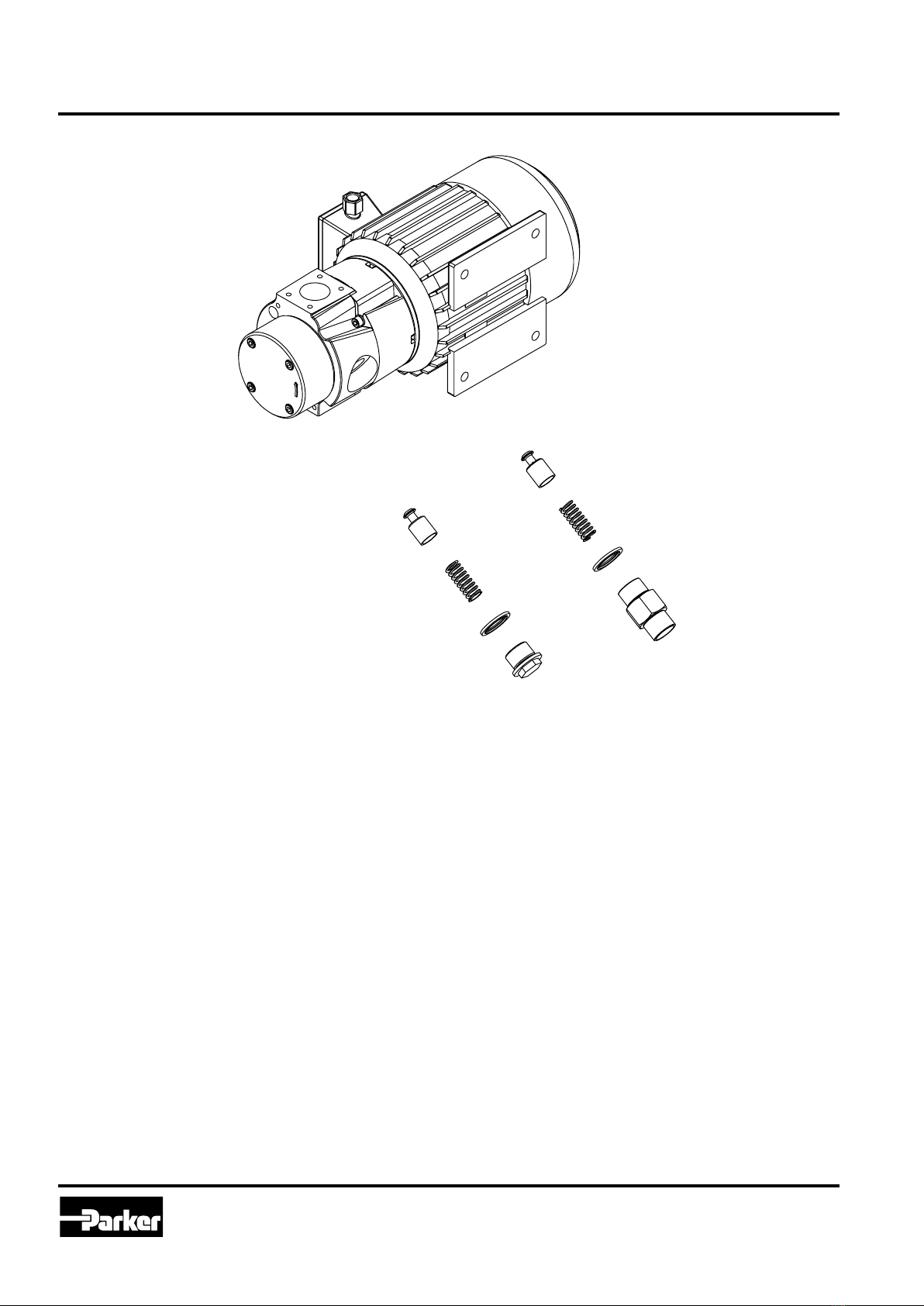
Low pressure pump, QPM3
10 Parker Hannin Corporation
Hydraulics Group
Catalogue HY10-6012-UM/EU
Installation/Handling
Installation
Lifting
Caution Risk of bodily injury. To prevent bodily injury when
lifting the pump, ensure correct lifting technique is used.
Make sure that all lifting devices are working properly and
that they are approved for the weight of the pump. Use
lifting straps under the pump unit to prevent bodily injury.
Mounting
Precaution Risk of bodily injury. Make sure that all parts of
the pump are firmly secured.
An upright position of the QPM3 pump, standing on the electric mo-
tor feet is recommended.
The pump can be mounted in any position in steps of 90° in relation
to the electric motor.
To achieve optimum pump capacity, install the unit below tank oil le-
vel (max. 5 meter) and as close to the tank as possible. When instal-
led above tank oil level, minimize the difference in height and install
a check valve or shut-off valve at the pump inlet. Place the unit to
ensure adequate air flow through the electric motor.
The acoustic pressure level could reach 65-67 dB(A) LpA at a dis-
tance of 1 m under normal conditions. Inappropriate location or ope-
ration under extreme conditions could generate increased acoustic
power level.
Oil connection
Connect the QPM3 low pressure pump using flexible hydraulic
hoses. Make sure that all connections and hoses are sized
according to the system pressure, flow, temperature and type of
oil. Connect the hydraulic hoses as illustrated in figure 2.
A– Inlet.
B– Outlet.
Maximum permitted oil temperature is 100 °C.
The size of the inlet line should not be inferior to the pump
connection size. A larger size is recommended.
Avoid flow rates in excess of 1 m/s in the pump inlet line.
Maximum pressure on the pump suction side is 0.5 bar.
Maximum suction pressure in the pump inlet line with oil filled pump
is 0.4 bar.
Parker will not be held responsible for the consequences of any
modification or variation with regard to connections.
Electrical connection
Danger Electrical shock hazard. All electrical connections
must be made by a qualied electrician!
Prior to connecting the motor to the electrical supply system,
make sure that the specification on the electric motor rating plate
corresponds to the mains supply voltage and frequency. The
electric motor should be installed according to general rules and
electrical safety regulations and must be installed by a qualified
electrician.
Caution Risk of personal injury and damage to property.
Be careful when connecting the equipment. Improperly
made connections, damaged cables, etc. could cause
parts to become current carrying or result in incorrect
direction of rotation of the electric motor and pump.
See Figure 3.
Important Do not exceed the maximum rated current for the
electric motor, see electric motor rating plate.
Note! An electric motor overload protection is recommended.
In extremely humid environments, especially when the operation
is intermittent, condensation may form. Some motors are fitted
with plugged holes, which can be used to drain condensed water.
Depending on the placement of the electric motor, proper plugs
should be removed.
If the QPM3 low pressure pump is installed in an environment
where water may penetrate into the electric motor, use a protective
shield. The protective shield is available as an option.
Handling
Prior to initial start-up
Precaution Make sure that the unit is securely fixed and
correctly connected. We recommend to run the pump with
the same oil as used in the hydraulic system. See Technical
specification for oil compatibility.
Note! Air in the inlet line could sometimes cause problems at initial
start-up. Make sure that the pump inlet is always filled with oil.
Prior to start up
Precaution DMake sure that the pump can be put into
service without causing bodily injury or damage to property
or environment.
Make sure that:
• ltall hydraulic connections are tight,
• valves and similar throttling devices are open and
that conduits and couplings are not damaged.
At start-up
Make sure that:
• the direction of rotation corresponds to indications on the
pump cover by looking at the electric motor fan, see Figure 4,
• the oil lter is free from abnormal noise and vibrations.
Make sure not to overload the electric motor due to cold start
conditions or operation with high oil viscosity.
Recommended operating viscosity range is 10 – 800 cSt con-
sidering the motor power. Consult your local Parker office when
using high viscosity oils or when the pump is operating in cold
start condition.
For long service life, oil cleanliness should, according to ISO
4406, not be below 17/15.
Note! Air in the inlet line could cause problem at start-up.
Make sure that the pump inlet is always filled with oil.
During operation
Caution Risk of personal injury and damage to property.
The pump must not be run in such a way that the maximum
pressure is exceeded, which could occur if the pump outlet
is closed or severely throttled. This could damage the unit
and cause personal injury.
Important Risk of heat release. Avoid internal recirculation during
a long period of time.
Note! Use hearing protection when standing in the immediate
vicinity of an operating pump for long periods of time.
The pump is not provided with by-pass valve as standard.
Use pump with by-pass valve if the system is provided with shut-
off valves etc. or if the pump is exposed to cold starts.
Pump with internal or external by-pass valve is available as option.


 null")