2
1 Safety Information
Important: Do not operate this equipment until the safety information and instructions in this user guide have been read and understood by all
personnel concerned.
Only competent personnel trained, qualified, and approved by Parker domnick hunter should perform installation, commissioning,
service and repair procedures.
Use of the equipment in a manner not specified within this user guide may result in an unplanned release of pressure, which may cause serious
personal injury or damage.
When handling, installing or operating this equipment, personnel must employ safe engineering practices and observe all related regulations,
health & safety procedures, and legal requirements for safety.
Ensure that the equipment is depressurised and electrically isolated, prior to carrying out any of the scheduled maintenance instructions
specified within this user guide.
Most accidents that occur during the operation and maintenance of machinery are the result of failure to observe basic safety rules and
procedures. Accidents can be avoided by recognising that any machinery is potentially hazardous.
Parker domnick hunter can not anticipate every possible circumstance which may represent a potential hazard. The warnings in this manual
cover the most known potential hazards, but by definition can not be all-inclusive. If the user employs an operating procedure, item of equipment
or a method of working which is not specifically recommended by Parker domnick hunter the user must ensure that the equipment will not be
damaged or become hazardous to persons or property.
Should you require an extended warranty, tailored service contracts or training on this equipment, or any other equipment within the Parker
domnick hunter range, please contact your local Parker domnick hunter office.
Details of your nearest Parker domnick hunter sales office can be found at www.parker/dhfns.com
Retain this user guide for future reference.
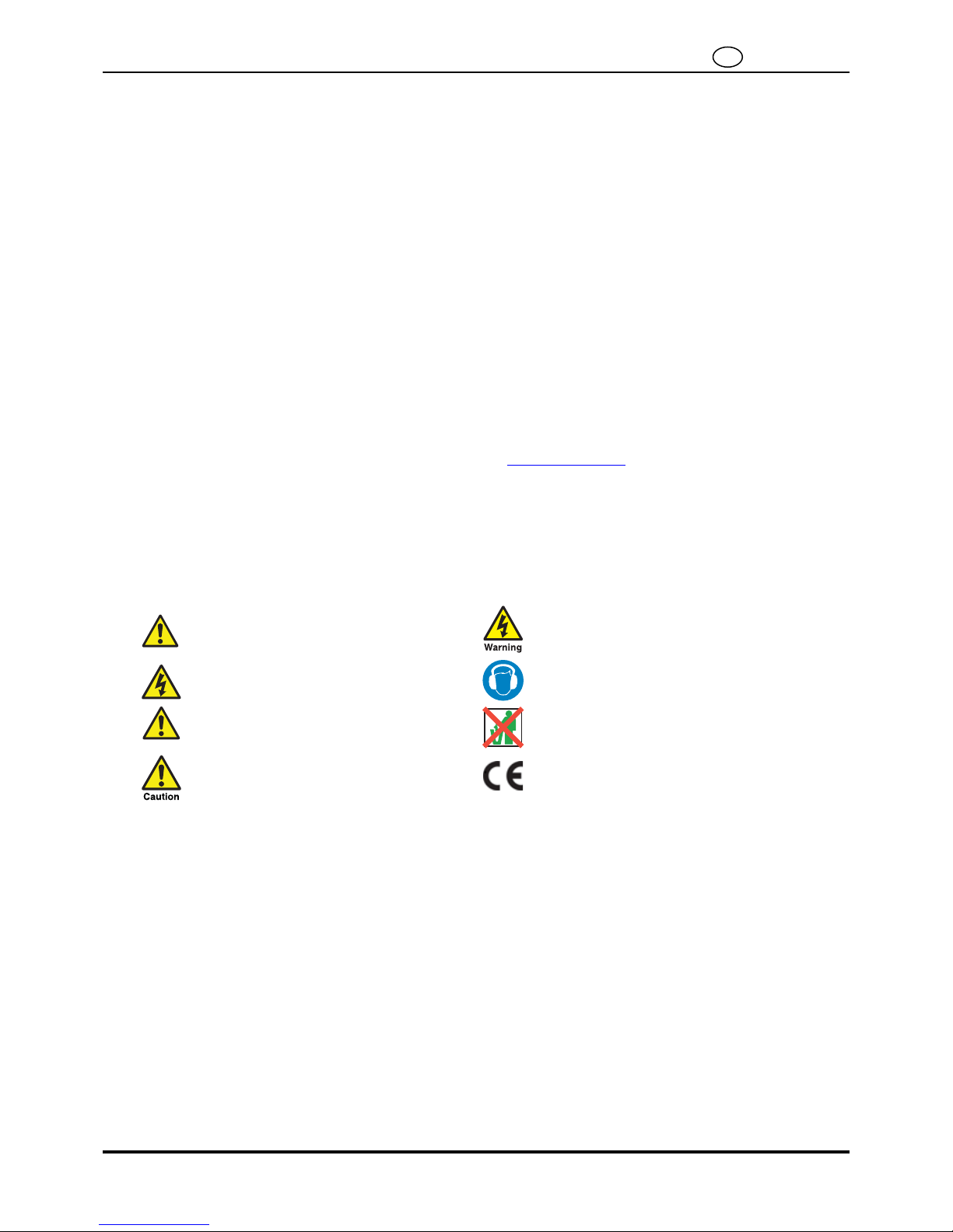
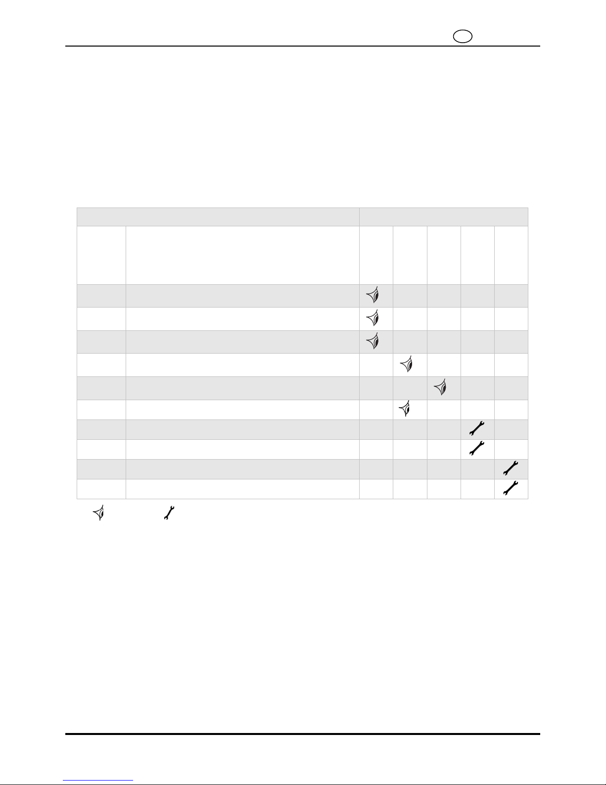
1.1 Markings and Symbols
The following markings and international symbols are used on the equipment and within this user guide:
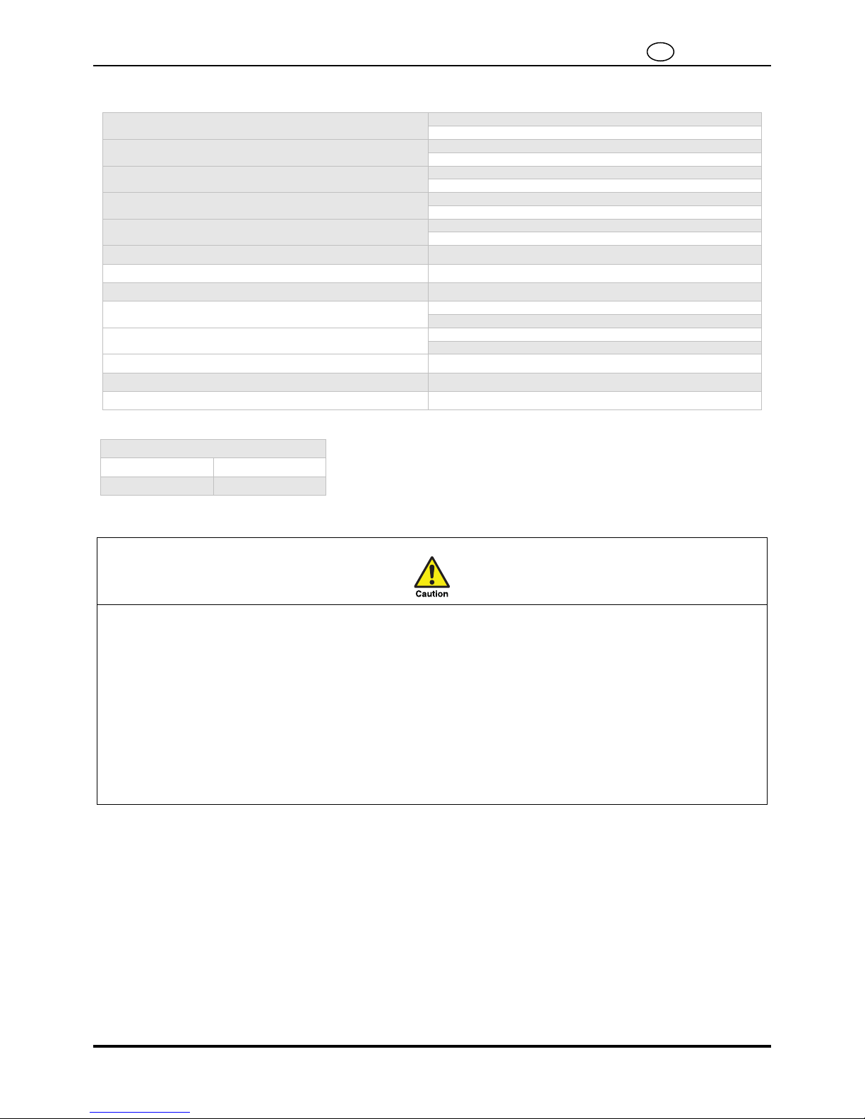
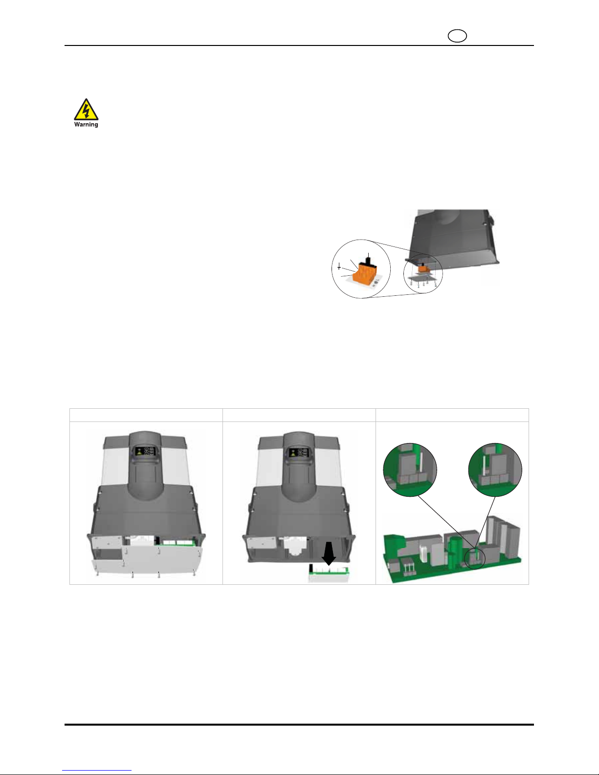
1.2 Hazardous Substances
The chambers of the dryer are filled with DRYFIL desiccant material. This is a powerful desiccant and will dry out the atmosphere, eyes, nose,
and mouth.
If the desiccant comes into contact with the eyes or skin, wash the affected area with copious amounts of water.
DRYFIL may contain some dust therefore an orinasal dust respirator should be worn when handling the equipment. Adequate ventilation should
be provided when working with desiccant.
The desiccant is classified as non-hazardous for transportation.
DRYFIL will evolve heat on contact with moisture and may generate pressure in a confined space. DRYFIL should therefore be stored in a dry
place in its original packaging.
DRYFIL is non-flammable. Any fire should be fought by means appropriate to the material causing the fire.
DRYFIL should be disposed of into a licensed land fill site.
Caution, Read the User Guide. Highlights actions or procedures which, if not
performed correctly, could lead to electric shock.
Risk of electric shock. Wear hearing protection.
Highlights actions or procedures which, if not
performed correctly, may lead to personal injury or
death.
When disposing of old parts always follow local
waste disposal regulations.
Highlights actions or procedures which, if not
performed correctly, may lead to damage to this
product. Conformité Européenne


 null")