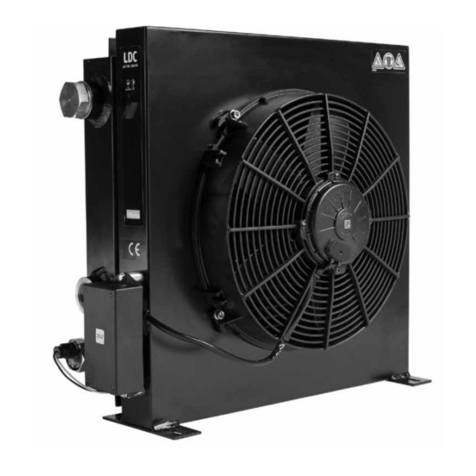
Parker LOC Datasheet

Air Oil Coolers
LOC Cooling System for industrial Use
Installation and servicing manual
aerospace
climate control
electromechanical
filtration
fluid & gas handling
hydraulics
pneumatics
process control
sealing & shielding

Installation and servicing manual
Air Oil Coolers, LOC
2Parker Hannin Corporation
Hydraulics Group
Catalogue HY10-6003-UM/EU
AIR OIL COOLER
LOC
AIR OIL COOLER
LOC
1
5
4
13
2
A
1/2 A
B
B
1/2 A
A
A
CB
B
CD
3
D

Installation and servicing manual
Air Oil Coolers, LOC
3Parker Hannin Corporation
Hydraulics Group
Catalogue HY10-6003-UM/EU
6
Y- koppling
Y- connection
Y- Anschluss
Connexion en Y
Conexión en Y
D- koppling
D- connection
D- Anschluss
Connexion en D
Conexión en D
Y-koppling
Y-connection
Y-Anschluss
Connexion en Y
Conexión en Y
D-koppling
D-connection
D-Anschluss
Connexion en D
Conexión en D

Installation and servicing manual
Air Oil Coolers, LOC
4Parker Hannin Corporation
Hydraulics Group
Catalogue HY10-6003-UM/EU
AIR OIL COOLER
LOC
AIR OIL COOLER
LOC
AIR OIL COOLER
LOC
11 A12
10
9
11 B
78

Installation and servicing manual
Air Oil Coolers, LOC
5Parker Hannin Corporation
Hydraulics Group
Catalogue HY10-6003-UM/EU
Komponentförteckning
AElmotor
BMotorfäste
CFläktgaller
DFläktenhet*
EFläkthus
FKylelement
GPluggar och gummistålbrickor
HFötter
ISlang med anslutningar
JKonsol
KPump
*Utförandet, fast eller löst nav, varierar
med typ av kylarsystem.
Part list
AElectric motor
BMotor attachment
CFan guard
DFan unit*
EFan housing
FCooler ma trix
GPlugs and rubber steel washers
HFeet
IHose wi th connections
JBracket
KPump
*The design, fixed or detachable hub, is
depending on type of cooling system.
Komponentenverzeichnis
AElektromotor
BMotorhalterung
CSchutzgitter
DLüftereinheit*
ELüftergehäuse
FKühlelement
GStopfen und Gummi stahlscheiben
HFüße
ISchlauch mi t Anschlüssen
JKonsole
KPumpe
*Die Ausführung mi t starrer oder loser
Nabe hängt vom Kühlermodell ab.
Liste des composants
AMoteur électrique
BSupport moteur
CGrille ventilateur
DHélice complète*
ECaisson ventilateur
FRadiateur
GBouchons et joints à lèvres
HPieds
IFlexible avec connections
JChaise
KPompe
*La conception, moyeu fixe ou non fixe, varie
suivant le type du système de refroidissement.
Lista de pi ezas
AMotor eléctrico
BSoporte de motor
CRejilla de protección ventilador
DVentilador completo*
ECaja del ventilador
FRadiador
GTapón ciego con junta metalbuna
HPatas
IFlexible hidráulico con conexiones
JConsola del motor
KBomba
*El asiento del ventilador, fijo o desmontable,
dependerá del tipo de sistema de refrigeración.
A
B
C
D
EF
G
H
I
J
K
Komponentförteckning
A Elmotor
B Motorfäste
C Fläktgaller
D Fläktenhet*
E Fläkthus
F Kylelement
G Pluggar och gummistålbrickor
H Fötter
I Slang med anslutningar
J Konsol
K Pump
* Utförandet, fast eller löst nav, varierar
med typ av kylarsystem.
Part list
A Electric motor
B Motor attachment
C Fan guard
D Fan unit*
E Fan housing
F Cooler matrix
G Plugs and rubber steel washers
H Feet
I Hose with connections
J Bracket
K Pump
* The design, fixed or detachable hub, is
depending on type of cooling system.
Komponentenverzeichnis
A Elektromotor
B Motorhalterung
C Schutzgitter
D Lüftereinheit*
E Lüftergehäuse
F Kühlelement
G Stopfen und Gummistahlscheiben
H Füße
I Schlauch mit Anschlüssen
J Konsole
K Pumpe
*
Die Ausführung mit starrer oder loser
Nabe hängt vom Kühlermodell ab.
Liste des composants
A Moteur électrique
B Support moteur
C Grille ventilateur
D Hélice complète*
E Caisson ventilateur
F Radiateur
G Bouchons et joints à lèvres
H Pieds
I Flexible avec connections
J Chaise
K Pompe
* La conception, moyeu fixe ou non fixe, varie
suivant le type du système de refroidissement.
Lista de piezas
A Motor eléctrico
B Soporte de motor
C Rejilla de protección ventilador
D Ventilador completo*
E Caja del ventilador
F Radiador
G Tapón ciego con junta metalbuna
H Patas
I Flexible hidráulico con conexiones
J Consola del motor
K Bomba
* El asiento del ventilador, fijo o desmontable,
dependerá del tipo de sistema de
refrigeración.

Installation and servicing manual
Air Oil Coolers, LOC
6Parker Hannin Corporation
Hydraulics Group
Catalogue HY10-6003-UM/EU
B
ACD
I
H
G
F
E
G
Ti llval
BS-Bypass, enpassage*
CDammskydd
DStenskydd
ET- Bypass, tvåpassage*
FTermokontakt
HTryckfallsindikatorer
IFilterenhet
* Kan fås som tryckstyrd eller temperatur-
och tryckstyrd bypass.
Ti llbehör
ALyftöglor
GVibrationsdämpare
Options
B S by-pass, single-pass*
C Dust guard
D Stone guard
E T by-pass, two-pass*
F Thermo contact
H Pressure drop indicator
I Filter unit
* Pressure controlled or temperature and
pressure controlled by-pass valves are availble.
Accessories
A Lifting eye
G Vibration dampener
Sonderzubehör
BS-Bypass, Einzeldurchlauf*
CStaubschutz
DSteinschutz
ET- Bypass, Doppeldurchlauf*
FThermokontakt
HDi fferenzdruckanzeigen
IFilter
* Mi t Drucksteuerung oder Temperatur-
und Drucksteuerung lieferbar.
Zubehör
AHebeösen
GVibrationsdämpfer
Equipements en option
BBypass type S, modèle 1 passe*
CFiltre antipoussière
D Grille de protection
E Bypass type T, modèle 2 passes*
F Thermocontact
H Inidcateurs de comatage
I Filtre
* Di sponsible comme bypass commandé par
pression ou par température et pression
Accessoires
A Anneaux de levage
G Patins antivibratoires
Opci ones
B By-pass tipo S, 1 paso*
C Filtro antipolvo
D Protección piedras
E By-pass tipo T, 2 pasos*
F Termocontacto
H Di spositivo de presión di ferencial
I Conjunto filtro
* Di sponible como bypass controlado por pre
ción o por temperatura y presión
Accesorios
A Cáncamos de elevación
G Silent blocs
Tillval
B S-Bypass, enpassage*
C Dammskydd
D Stenskydd
E T-Bypass, tvåpassage*
F Termokontakt
H Tryckfallsindikatorer
I Filterenhet
* Kan fås som tryckstyrd eller temperatur-
och tryckstyrd bypass.
Tillbehör
A Lyftöglor
G Vibrationsdämpare
Options
B S by-pass, single-pass*
C Dust guard
D Stone guard
E T by-pass, two-pass*
F Thermo contact
H Pressure drop indicator
I Filter unit
* Pressure controlled or temperature and
pressure controlled by-pass valves are availble.
Accessories
A Lifting eye
G Vibration dampener
Sonderzubehör
B S-Bypass, Einzeldurchlauf*
C Staubschutz
D Steinschutz
E T-Bypass, Doppeldurchlauf*
F Thermokontakt
H Differenzdruckanzeigen
I Filter
* Mit Drucksteuerung oder Temperatur-
und Drucksteuerung lieferbar.
Zubehör
A Hebeösen
G Vibrationsdämpfer
Equipements en option
B Bypass type S, modèle 1 passe*
C Filtre antipoussière
D Grille de protection
E Bypass type T, modèle 2 passes*
F Thermocontact
H Inidcateurs de comatage
I Filtre
*
Disponsible comme bypass commandé par
pression ou par température et pression
Accessoires
A Anneaux de levage
G Patins antivibratoires
Opciones
B By-pass tipo S, 1 paso*
C Filtro antipolvo
D Protección piedras
E By-pass tipo T, 2 pasos*
F Termocontacto
H Dispositivo de presión diferencial
I Conjunto filtro
*
Disponible como bypass controlado por pre
ción o por temperatura y presión
Accesorios
A Cáncamos de elevación
G Silent blocs

Installation and servicing manual
Air Oil Coolers, LOC
7Parker Hannin Corporation
Hydraulics Group
Catalogue HY10-6003-UM/EU
Contents
Inledning 8
Säkerhetsföreskrifter 8
Beskrivning 8
Installation 9
Handhavande 9
Förebyggande underhåll 10
Underhåll 10
Tekniska data 13
Försäkran om överensstämmelse 14
Introduction 15
Safety instructions 15
Description 15
Installation 16
Handling 16
Preventive maintenance 17
Maintenance 17
Technical specification 20
Declaration of conformity 21
Einleitung 22
Sicherheitsvorschriften 22
Beschreibung 23
Installation 23
Bedienung 24
Vorbeugende Wartung 24
Wartung 25
Technische Daten 27
Konformitätserklärung 28
Introduction 29
Consignes de sécurité 29
Description 30
Installation 30
Consignes d’emploi 31
Entretien préventif 31
Entretien 32
Caractéristiques techniques 35
Déclaration de conformité 36
Introducción 37
Instrucciones de seguridad 37
Descripción 38
Instalación 38
Modo de empleo 39
Mantenimiento preventivo 39
Mantenimiento 40
Características técnicas 43
Declaración de conformidad 44
SE
GB
DE
FR
ES

Installation and servicing manual
Air Oil Coolers, LOC
8Parker Hannin Corporation
Hydraulics Group
Catalogue HY10-6003-UM/EU
Inledning
Denna anvisning är avsedd att vara ett hjälpmedel vid installation,
användning och underhåll av LOC kylsystem.
Förvara anvisningen så att den alltid finns till hands.
Ersätt omedelbart en förlorad anvisning.
Läs igenom anvisningen och varningstexterna noggrant och se till
att förstå innehållet innan du använder kylsystemet.
På så sätt får du ut mesta möjliga av ditt kylsystem och felaktig
användning undviks.
Endast för ändamålet utbildad personal får installera, handha och
underhålla kylsystemet.
Parker förbehåller sig rätten till tekniska ändringar.
Avsedd användning
LOC kylsystem är avsett för kylning och rening (tillval) av olja i
hydraulsystem för industriella applikationer.
Garanti och reklamation
Vid haveri, kontakta Parker. Parker ansvarar inte för LOC kylsys-
tem efter egenhändiga reparationer och/eller modifieringar.
Säkerhetsföreskrifter
Installatör och brukare ska känna till, förstå och beakta varningar
eller upplysningar som anges på dekaler, skyltar och i denna
anvisning.
Varningsnivåer och uppmärksamhetstexter...
...gällande personlig säkerhet
Uppmärksamhetstexter, som har med personlig säkerhet att
göra, är klassade i tre nivåer, enligt nedan, beroende på hur all-
varliga följderna av en olycka kan bli.
Fara anger att en olycka kommer att inträffa om
föreskriften inte följs. Olyckan leder till allvarlig personskada
eller möjligen dödsfall.
Varning anger att en olycka kan komma att inträffa om
föreskriften inte följs. Olyckan kan leda till allvarlig person-
skada eller möjligen dödsfall.
Försiktighet anger att en olycka kan komma att inträffa
om föreskriften inte följs. Olyckan kan leda till personskada.
...gällande övrig säkerhet
Uppmärksamhetstexter som har med övrig säkerhet (egendom,
process eller omgivning) och handhavande att göra är klassade
enligt följande:
Viktigt anger att en olycka kan komma att inträffa om föreskrif-
ten inte följs. Olyckan kan leda till skada på egendom, process
eller omgivning.
...gällande tilläggsinformation
Tilläggsinformation markeras enligt följande:
Anm! Anger extra information som kan underlätta förståelse för,
eller utförande av, ett visst moment.
Övergripande föreskrifter
Lyft
Varning Kläm-/krossrisk. För att undvika personskador vid
lyft är det viktigt att använda rätt lyftmetod. Kontrollera att
den lyftanordning och de lyftdon som används är felfria och
godkända för kylsystemets vikt.
Installation
Fara Risk för elchock. Elektrisk anslutning får endast
utföras av behörig elektriker!
Drift, hantering och underhåll
Varning Risk för personskada. Koppla alltid bort
drivkällan för motorn innan underhåll.
Varning Risk för personskada. Se till att systemet är
trycklöst innan hydraulanslutningar kopplas bort.
Varning Risk för allvarlig brännskada. Vid drift kan
kylsystemet bli mycket varmt. Vidrör ej kylsystemet
förrän det har svalnat.
Försiktighet Klämrisk. Kylsystemet kan styras via en
termokontakt. Fläkten startar då automatiskt vid upp-
nådd temperatur. Var försiktig vid vistelse nära roterande
komponenter.
Försiktighet Risk för förgiftning. Förbrukad olja skall
lämnas på därför avsedd depå för att inte orsaka skada
på person, egendom eller miljö.
Viktigt Statisk elektricitet. Fläktar alstrar statisk elektricitet.
Undvik känslig utrustning (elektronik m.m.) i systemets omedelbara
närhet.
Antistatiska fläktar finns att beställa.
Anm! Använd hörselskydd vid vistelse under en längre tid i när-
heten av ett kylsystem i drift.
Varningsdekal
Nedanstående dekal är fäst på LOC kylsystem vid leverans.
Varning! Heta ytor! Använd hörselskydd! Roterande fläkt!
(art.nr. 500029 – 70 x 30 mm alt.
art.nr. 5000291 – 120 x 50 mm) Se Bild 1.
Beskrivning
LOC kylsystem består i huvudsak av en luftoljekylare, en
växelströmsmotor samt en lågtryckspump ur vår QPM-serie.
Kylsystemet kan med fördel även förses med en filterenhet för
rening av oljan.
LOC kylsystem finns med kyleffekt 2,7 - 44,8 kW samt med
nominellt oljeflöde 20-80 l/min.
Märkskylt kylsystem
Kylsystemets märkskylt är placerad på fläkthuset. Se Bild 2.
På märkskylten finns information om:
A– Artikelnummer
B– Artikelbenämning
C–Serienummer
D – Leveransdatum
(år och vecka, t.ex. 1018, dvs år 2010 och vecka 18).
Ersätt skadad eller saknad skylt omedelbart.
Märkskylt filterenhet
På filterenhetens märkskylt finns följande information:
• Artikelnummer på lterpatron
• Benämning på lterpatron (04” HP).
Inledning/Säkerhetsföreskrifter/Beskrivning

Installation and servicing manual
Air Oil Coolers, LOC
9Parker Hannin Corporation
Hydraulics Group
Catalogue HY10-6003-UM/EU
Installation
Lyft
Varning Kläm-/krossrisk. För att undvika personskador vid
lyft är det viktigt att använda rätt lyftmetod. Kontrollera att
den lyftanordning och de lyftdon som används är felfria och
godkända för kylsystemets vikt.
LOC kylsystem är från och med storlek 033 förberedda för lyftög-
lor. Lyftöglor finns att beställa som tillbehör.
Montering
Försiktighet Risk för personskador. Se till att kyl systemets
alla delar är ordentligt fixerade.
Parker rekommenderar att installera LOC kylsystem horisontellt,
stående på kylsystemets fötter. För att undvika personskador, se
alltid till att kylsystemet är ordentligt fastsatt.
För att uppnå god luftgenomströmning och därmed bästa möjliga
kyleffekt och lägsta möjliga ljudtrycksnivå, lämna ett utrymme
motsvarande åtminstone halva elementhöjden fritt framför och
bakom kylsystemet. Se Bild 3.
Om systemet är utrustat med filterenhet, se till att ett utrymme
motsvarande filterpatronens storlek lämnas fritt över filtret för att
förenkla vid byte av filterpatron. Se Bild 3.
Ljudtrycksnivån kan uppgå till 57-86 dB(A) LpA vid 1 m avstånd
under normala driftsförhållanden. Olämplig placering av
kylsystemet, eller drift under extrema förhållanden, kan orsaka
förhöjd ljud trycksnivå och sämre kyleffekt.
För att förhindra att tanken töms vid byte av filterpatron, bör
kylsystemets vätskenivåvara högreän tankens vätskenivå.Om detta
inte är möjligt, installera en backventil eller en avstängningsventil i
systemets in- och utlopp.
Anslutning av kylsystemet
Använd hydraulslangar för att ansluta kylsystemet. Se till att
kopplingar och slangar är dimensionerade efter hydraulsystemets
tryck, flöde, temperatur och typ av olja.
Anslut hydraulslangarna till pumpenheten enligt Bild 4.
A– Inlopp.
B– Utlopp för modell S-bypass, enpassage.
C- Utlopp för modell T-bypass, två-passage.
D- Anslutning för termokontakt.
Maximalt tillåten oljetemperatur är 100 °C.
Dimensioner på anslutningar beror på kylsystemets storlek.
Maximalt tillåten vätsketemperatur i kylsystemet är 100 °C.
Flödesschema, se Bild 5.
För bästa möjliga pumpeffekt, placera kylsystemet under tankens
vätskenivå (max. 5 meter) och så nära tanken som möjligt. Vid
montering ovanför tankens vätskenivå, skall höjdskillnaden
minimeras.
Inloppsledningens diameter bör inte vara mindre än pumpens
anslutningsdiameter. En grövre diameter rekommenderas.
Undvik strömningshastigheter över 1 m/s i pumpens ingående
oljeledning. Maximalt tryck på pumpens sugsida är 0,5 bar.
Elektrisk anslutning
Fara Risk för elchock. Elektrisk anslutning får endast utföras
av behörig elektriker!
Innan inkoppling av motorn till elnätet, se till att uppgifterna på
motorns märkskylt överensstämmer med nätets spänning och
frekvens.
Elmotorn ska installeras i enlighet med allmänt gällande regler och
elsäkerhetsföreskrifter och måste installeras av en behörig elektriker.
Försiktighet Var noggrann vid inkoppling. Felaktig
inkoppling, skadade kablar, etc. kan ge upphov till
strömförande komponenter och fel rotationsriktning på
motor, fläkt och pump. Se Bild 6.
Viktigt Elmotorns märkström får inte överskridas, se märkplåt på
elmotorn.
Anm! Parker rekommenderar att använda överströmsskydd för
elmotorn.
I mycket fuktig miljö, speciellt i samband med intermittent
drift, kan kondens vatten bildas i elmotorn. Vissa elmotorer är
försedda med pluggade hål som kan användas som utlopp för
eventuellt kondensvatten. Beroende på elmotorns placering bör
dräneringspluggarna avlägsnas.
LOC kylsystem kan förses med termokontakt för temperaturlarm.
Fläkten startar då automatiskt vid uppnådd temperatur. Använd
relä vid högre belastning än vad som är tillåtet för termokontakten.
Viktigt Termokontakten får ej användas för att direkt styra elmotorn.
Handhavande
Innan första uppstart
Försiktighet se till att enheten kan startas utan risk för
skada på person, egendom eller miljö.
Kontrollera att:
• kylsystemets delar inte är skadade
• äkten roterar fritt (använd handkraft)
• alla hydrauliska anslutningar är åtdragna
• äkthusets insida är fri från föremål som kan slungas iväg och
orsaka skador på person eller egendom
• ventiler eller liknande strypdon är öppna samt att ledningar eller
kopplingar inte är skadade.
Se Tekniska data för rekommenderade vätskekombinationer.
Innan start
Försiktighet Se till att enheten kan startas utan risk för
skada på person, egendom eller miljö.
Kontrollera att:
• alla hydrauliska anslutningar är åtdragna
• ventiler eller liknande strypdon är öppna samt att ledningar eller
kopplingar inte är skadade.
Installation/Handhavande

Installation and servicing manual
Air Oil Coolers, LOC
10 Parker Hannin Corporation
Hydraulics Group
Catalogue HY10-6003-UM/EU
Vid start
Kontrollera att:
• äktens rotationsriktning och luftöde överensstämmer med
indikering på fläkthuset
• inga onormala ljud och vibrationer förekommer
• kylsystemet inte läcker.
Se till att inte överbelasta motorn vid kallstart eller på grund av
alltför hög viskositet.
Viskositetsområde är 10 – 800 cSt med beaktande av pump,
motorkapacitet, filterdimension etc.
Kontakta Parker vid användning av oljor med hög viskositet
(t.ex. tjock smörjolja) eller vid kallstarter.
För problemfri drift bör oljans renhetsklass enligt ISO 4406 vara
minst 17/15.
Anm! Luft i inloppsledningen kan orsaka problem vid
igångsättning, fyll då ledningen med olja.
Anm! Om kylsystemet är utrustat med en filterenhet FX3, se
avsnitt för Filterenhet FX3.
Under drift
Varning Risk för allvarlig brännskada. Vid drift kan kyl-
systemet bli mycket varmt. Vidrör ej kylsystemet förrän
den har svalnat.
Anm! Använd hörselskydd vid vistelse under en längre tid i
närheten av ett kylsystem i drift.
Varning LOC kylsystem får ej köras så att pumpens maximalt
tillåtna tryck överskrids, vilket kan inträffa om oljeledningen på
pumpens utloppssida är stängd eller kraftigt strypt. (Se separat
broschyr för pumpen). Detta kan både skada pumpen och
orsaka personskador.
Pumpen saknar tryckbegränsningsventil som standard.
Välj pump med tryckbegränsningsventil om systemet t.ex.
är utrustat med avstängningsventil samt om pumpen utsätts
för kallstarter. Som tillval finns internt eller externt dränerad
bypassventil färdigmonterad i pumpen.
Förebyggande underhåll
De viktigaste underhållsåtgärderna är de förebyggande
åtgärderna som brukaren ska utföra med jämna intervaller.
Kontrollera att:
• inga onormala ljud och vibrationer förekommer
• kylsystemet är ordentligt fastsatt
• kylsystemet är rent, smuts försämrar kyleffekten
• kylsystemet är fritt från skador, byt ut skadade komponenter
• kylsystemet inte läcker
• varningsdekaler är i gott skick, ersätt skadade eller saknade
dekaler omedelbart.
Årligen: Kontrollera den elektriska installationen. Detta får en-
dast utföras av behörig elektriker.
Pumpen är under normala driftsförhållanden underhållsfri.
Drift under extrema förhållanden kräver inspektion och underhåll
eller utbyte av pump och/eller koppling. Se separat broschyr för
pumpen.
Rengöring
Varning Risk för personskada. Koppla bort drivkällan
för motorn innan rengöring.
Varning Risk för allvarlig brännskada. Vid drift kan kyl-
systemet bli mycket varmt. Vidrör ej kylsystemet förrän
det har svalnat.
Kylsystem Vid yttre rengöring av kylsystemet med exempelvis
vatten, ska alla elanslutningar kopplas från. Beakta elmotorns
kapslingsklass.
Kylelement Kylelementets luftlameller rengörs enklast
med tryckluft. Vid behov, använd högtryckstvätt med
avfettningsmedel. Vid högtrycksspolning måste strålen föras
parallellt med lamellerna. Se Bild 7.
Fläkthus Demontera kylelementet vid invändig rengöring av
fläkthuset. Insidan av fläkthuset rengörs enklast med tryckluft.
Vid behov, använd avfettningsmedel. Blås med tryckluft från
elmotorsidan genom fläktgallret.
Pump Parker ansvarar inte för ingrepp i pumpen vid t ex invän-
dig rengöring. Om pumpen har körts med smutsig olja rengörs
den genom att köras med ren olja.
Filterenhet (tillval) Filterpatroner kan inte rengöras.
Underhåll
Demontering Parker ansvarar inte för konsekvenser efter
egenhändigt, av kunden, utförda reparationer eller modifie-
ringar.
Varning Risk för allvarlig brännskada. Vid drift kan kyl-
systemet bli mycket varmt. Vidrör ej kylsystemet förrän
det har svalnat.
Varning Risk för personskada. Koppla bort drivkällan
för motorn vid underhåll.
Viktigt Använda patroner får ej kastas i vanlig sophantering
utan skall lämnas in på därför avsedda depåer/stationer.
Demontering av kylelement
1. Stäng av systemet.
2. Koppla bort drivkällan för motorn.
3. Se till att systemet är trycklöst.
4. Stäng oljeanslutningarna.
5. Koppla bort hydraulslangarna.
6. Skruva loss skruvarna med brickor som fäster kylelementet i
fläkthuset. Se Bild 8.
7. Lyft bort kylelementet.
Montering av kylelement
1. Lyft kylelementet på plats.
2. Skruva fast kylelementet i fläkthuset. Se Bild 8.
3. Anslut hydraulslangarna till kyl elementet. Se Bild 4.
4. Koppla till drivkällan för motorn.
5. Utför åtgärder enligt Innan start och Vid start.
Förebyggande underhåll/Underhåll

Installation and servicing manual
Air Oil Coolers, LOC
11 Parker Hannin Corporation
Hydraulics Group
Catalogue HY10-6003-UM/EU
Demontering av pump och koppling
1. Stäng av systemet.
2. Koppla bort drivkällan för motorn.
3. Se till att systemet är trycklöst.
4. Stäng oljeanslutningarna.
5. Koppla bort hydraulslangarna från kylelementet.
6. Skruva ur skruvarna och gummistålbrickorna som håller
pumpen till elmotorn.
7. Tag bort pumpen och kopplingens kuggkrans.
Pumpen och kopplingsdelarna kan nu bytas ut.
8. Lossa stoppskruven i axelkopplingsdelen.
Ta bort axelkopplingsdelen från elmotoraxeln.
Montering av pump och koppling
1. Installera axelkopplingsdelen på elmotoraxeln.
Installera stoppskruven.
2. Installera pumpen och kopplingens kuggkrans.
3. Skruva i skruvarna och gummistålbrickorna som håller
pumpen till elmotorn.
4. Anslut hydraulslangarna till kylelementet. Se Bild 4.
5. Koppla till drivkällan för motorn.
6. Utför åtgärder enligt Innan start och Vid start.
Demontering av elmotor och fläkt
Varning Risk för allvarlig brännskada. Vid drift kan
kylsystemet bli mycket varmt. Vidrör ej kylsystemet
förrän det har svalnat.
Varning Risk för personskada. Koppla bort drivkällan
för motorn vid underhåll.
Fläkten är balanserad tillsammans med navet vid leverans.
Anm! Vissa modeller har fast nav, se Bild 10, andra modeller
har löst nav, se Bild 11 A och Bild 11 B.
1. Stäng av systemet.
2. Demontera pumpen enligt Demontering av pump och
koppling.
3. Säkra motorn.
4. Skruva loss skruvarna med brickor som fäster motorfästet i
fläkthuset. Se Bild 9.
5. Skruva loss skruvarna med brickor som håller
motorkonsolen till fötterna. Dra motorn bakåt.
6. Skruva loss skruven med bricka som fäster fläkten med nav
i motoraxeln. Se Bild 10. Dra försiktigt loss fläkten med nav
från motoraxeln. Använd avdragare vid behov.
7. Skruva loss skruvarna med brickor som håller motorn till
motor fästet. Se Bild 12.
8. Skruva loss skruvarna med brickor som håller motorn till
motorkonsolen.
9. Lyft bort motorn.
Vid ytterligare demontering av fläkt, märk upp alla delarna för
att säkerställa korrekt återmontering, framförallt med avseende
på balans och rotationsriktning. Se Bild 13.
Montering av elmotor och fläkt
Anm! Vissa modeller har fast nav, se Bild 10, andra modeller
har löst nav, se Bild 11 A och Bild 11 B.
1. Skruva fast motorn på motorkonsolen.
2. Skruva fast motorn i motorfästet. Se Bild 12.
3. Passa in spåret i navet mot krysskilen på motorn. Använd
etanol i navet som smörjning och tryck fast fläkten med nav
på motoraxeln. Knacka eventuellt försiktigt med t.ex. en
gummiklubba. Applicera Loctite på skruven och skruva fast
fläkten med navet i motoraxeln. Se Bild 10.
4. Kontrollera att fläkten sitter fast på motoraxeln och att den
inte glappar.
5. Lyft motorfästet med fläkt, fläktgaller, motor och motorkonsol
på plats för montering i fläkthuset.
6. Justera in fläktgallret och motorn och skruva fast motorfästet
i fläkt huset. Se Bild 9. Skruva fast motorkonsolen.
7. Kontrollera att fläkten är centrerad och roterar fritt (använd
handkraft). Vid behov justera placeringen av fläktgallret och
motorn.
8. Se till att alla skruvar är åtdragna.
9. Koppla motorn till drivkällan.
10.Utför åtgärder enligt Innan start och Vid start.
Filterenhet FX3
Med vår filterenhet typ FX3 filtreras oljan i en separat filterkrets,
ett bra komplement till systemets eget filter. Filterenhet FX3
finns som tillval.
Innan start
1. Avlufta filterenheten genom att öppna luftpluggen vid filteren-
hetens topp ca. två varv.
2. Fyll filterenheten gradvis tills all luft kommit ut och stäng
sedan luft pluggen.
3. Sätt systemet under fullt tryck och kontrollera om det inte
läcker. Om så är fallet, se Periodiskt underhåll.
Försiktighet Om filterenheten inte avluftas ordentligt,
stiger innehållet av löst luft i oljan, vilket förkortar dess
livslängd och kan även orsaka andra problem i hydraul-
systemet.
Periodiskt underhåll
Filterenheten fordrar normalt ingen speciell service utom
periodisk kontroll av tryckfallsindikatorn. Schemalägg byte av
filterpatron var sjätte månad eller oftare och ha alltid ett rikligt
förråd av patroner i reserv.
Varning Om trycket i filterenheten inte sänkts innan
filterpatronen lossas, kan det medföra skador på per-
son, egendom och miljö.
Underhåll

Installation and servicing manual
Air Oil Coolers, LOC
12 Parker Hannin Corporation
Hydraulics Group
Catalogue HY10-6003-UM/EU
Vid underhåll ska eventuell smuts på filterenhetens utvändiga
ytor avlägsnas. Underhåll ska göras med lämpliga verktyg.
Vid externt läckage ska O-ringen vid läckaget bytas ut. Om
läckaget fortsätter, kontrollera om repor eller sprickor finns på
tätningsytan. Byt ut defekta delar.
Ett smutsigt system kan snabbt sätta igen en ny filterpatron.
Det kan krävas ett eller två patronbyten för att stabilisera patro-
nens livslängd. Om livslängden är kort eller tryckfallet är högt,
kan filterenheten vara underdimensionerad, kontakta Parker.
Tryckfallsindikatorer
Tryckfallsindikatorer kontrollerar filterpatronens kondition
genom att mäta differentialtryckfallet mellan filtrets in-
och utlopp. Tryckfallsindikatorn arbetar oberoende av
överströmningsventilen och är avsedd att indikera före det
att ventilen öppnar. Detta innebär att det finns tid att byta
filterpatron innan överströmningsventilen öppnar och släpper
igenom ofiltrerad olja samt att filterpatronens livslängd utnyttjas
maximalt.
Om indikeringen ignoreras och nedsmutsningen fortsätter,
öppnas överströmningsventilen i filterenheten när tryckfallet
över filterpatronen uppnår 3,5 bar. Systemet fungerar därefter
enbart som kylsystem utan filtrering.
Indikator typ D
Om den visuella tryckfallsindikatorn typ D är monterad och
utlöser (den röda knappen skjuts ut 5 mm) under kallstart,
återställs den genom att trycka på knappen när normal
arbetstemperatur uppnåtts. Om indikatorn utlöses efter
återställning, byt filterpatron.
Indikator typ P
Den visuella indikatorn typ P har termoskydd, dvs om tempera-
turen understiger 0 °C sker ingen indikering förrän temperaturen
överstiger +29 °C. Denna indikator har manuell återställning.
Indikator typ M
Den elektriska tryckfallsindikatorn M har automatisk återställ-
ning och anslutning enligt DIN 43650, ISO4400 (Hirschmann)
och är fuktsäker enligt IP65. För effektiv övervakning av filterpa-
tronens livslängd, använd både positiv indikering (grön lampa)
och negativ indikering (röd lampa) för smutsig patron.
Om den elektriska tryckfallsindikatorn typ M används och
utlöser (dvs den röda lampan tänds) under kallstart, fortsätt
driften tills den röda lampan slocknar när systemet värmts upp
till normal arbetstemperatur. Denna funktion kan användas
som ”uppvärmningsindikering” i driftprocedurerna. Om den
röda lampan förblir tänd eller tänds när systemet är varmt, byt
filterpatron.
Indikator typ U
Den elektriska tryckfallsindikatorn U är försedd med en 2-polig
AMP kontakt.
Byte av filterpatron
1. Stäng av systemet och eventuell avstängningsventil.
2. Se till att systemet är trycklöst
3. Öppna luftpluggen på filterenhetens lock ca. två varv.
4. Skruva bort locket motsols, sett ovanifrån.
5. Lyft ur filterpatronen. Släng både filterpatron och packning.
Filterpatronen kan inte rengöras. Försök att rengöra filterpa-
tronen kan bryta ner filtermediet och leda till att förorenad
olja läcker genom filterpatronen. Använda patroner får ej
kastas i vanlig sophantering, utan skall lämnas in på därför
avsedda depåer/stationer. 6. Sätt i en ny filterpatron. Kon-
trollera att den har en O-ring i botten.
7. Sätt i en ny O-ring i filterenhetens lock och skruva på locket.
8. Starta pumpmotorn med luftpluggen öppen cirka två varv.
9. Drag åt avluftningsskruven när enbart olja flyter ut. Vid upp-
start kan tryckfallsindikatorn lösa ut på grund av hög viskosi-
tet. Återställ indikatorn. Kör inte systemet utan filterpatron.
Efter patronbyte återställ tryckfallsindikatorn genom att trycka
in den röda knappen. Den elektriska indikatorn återställs auto-
matiskt. När systemet nått normal arbetstemperatur, kontrol-
lera att den elektriska indikatorn inte har utlösts och/eller den
visuella varningsknappen har förblivit intryckt. Om den visuella
indikatorn skjuts ut på grund av kallstartsförhållande, återställ
den enligt beskrivning under Tryckfallsindikatorer.
Parker garanterar inte filterpatronens livslängd som vi inte råder
över utan som beror på förhållandena hos det system i vilket
filterenheten har installerats.
Anm! Enheten är försedd med patronutdragningsmekanism
som underlättar patronbyte. Då locket tas av låser flikarna på
patronens ändkåpa fast i locket varvid patronen automatiskt
dras av från hylsan.
Viktigt Försök inte att rengöra eller återanvända filterpatronen.
Filterpatronen ska bytas vid behov eller vid angivna intervaller,
maximalt sex månader.
Underhåll

Installation and servicing manual
Air Oil Coolers, LOC
13 Parker Hannin Corporation
Hydraulics Group
Catalogue HY10-6003-UM/EU
Teknisk data
Tekniska data
Kylsystem
Maximalt arbetstryck: 10 bar
Värmeöverföringstolerans: ± 6 %
Maximalt tillåten oljetemperatur: 100 °C
Kompatibilitet
Mineralolja
Syntetiska oljor
Vegetabiliska oljor
Vid drift med andra vätskor eller vid extrema driftsförhållanden,
kontakta Parker.
Material
Pumphus/Kylelement Aluminium
Filterenhet (tillval) Aluminium
Fläkthus Stål
Fläktblad/nav Glasfiberförstärkt polypropylen/aluminium
Fläktgaller Stål
Ytbehandling Elektrostatisk pulverlackering
Elmotor
3-fas asynkronmotor enligt IEC 60034-1
Rekommenderad omgivnings temperatur -20 °C - +40 °C
Isolationsklass F
Temperaturstegring B
Kapslingsklass IP 55
För märkström, se separat manual för elmotorn.

Installation and servicing manual
Air Oil Coolers, LOC
14 Parker Hannin Corporation
Hydraulics Group
Catalogue HY10-6003-UM/EU
Försäkran om överrensstämmelse
PARKER
A
Manufa
Produc
t
Person
Swede
n
Parker
H
Directi
v
relates
f
The pr
o
-
S
-
S
–
-
S
a
-
A
-
2
The ab
o
AB and
CE-ma
r
If the p
r
is also
n
service
directiv
e
Sätra,
J
A
ccumulator &
cturer:
t
:
authorised
n
AB
H
annifin M
a
v
e 2006/42/
E
f
ulfils all th
e
o
duct is in c
S
afety of
m
1/A1:2009
a
S
afety of
m
–
Hydrauli
c
S
afety of
m
a
nd lower l
i
Pumps an
d
A
1:2009/A
C
Electric mo
2
006/95/E
C
o
ve is valid
a complet
e
r
ked by Pa
r
r
oduct is no
n
ot CE-ma
r
until the pr
o
e
s and sta
n
J
anuary 15
Cooler Division
Pa
A
c
c
St
r
S
E
S
w
Ph
M
a
w
w
Pa
to compile
a
nufacturin
g
E
C, under
s
e
relevant
p
onformity
w
m
achinery –
a
nd SS-EN
m
achinery –
c
s, SS-EN I
S
m
achinery –
i
mbs, SS-E
d
pump unit
s
C
:2010.
tors used
o
C
and the E
for a comp
e
product is
r
ker Hannifi
n
t delivered
r
ked by Par
k
o
duct has
b
n
dards.
2013
_
_
_
Rik
a
Te
c
Pa
r
Europe - Sätr
a
EC De
c
rker Hanni
f
c
umulator
a
r
ömsätravä
g
E
-127 35 S
k
w
eden
one: +46 8
a
il: infoolae
r
w
w.parker.c
o
rke
r
LOC
A
the techni
c
g
Sweden
A
s
ole respon
p
rovisions o
f
w
ith the req
u
Basic con
c
ISO 1210
0
Safety req
u
S
O 4413:2
0
Safety dist
a
N ISO 138
5
s
for liquid
s
o
n the prod
u
lectromagn
lete produ
c
n
Manufact
complete b
k
er Hanni
f
i
n
b
een declar
_
________
_
a
rd Erikss
o
c
hnical Ma
n
r
ker Hannifi
a
· Box 8064 ·
1
c
laration o
f
f
in Manufac
a
nd Cooler
g
en 16
k
ärholmen
636 07 00
r
.se@park
e
o
m
A
ir oil coole
r
c
al file: Rik
a
A
B declare
s
sibility that
f
the Machi
u
irements i
n
c
epts, gene
r
0
-2/A1:200
9
u
irements f
o
0
10.
a
nces to pr
e
5
7:2008.
s
– Commo
n
u
ct comply
w
etic Comp
a
c
t delivered
uring Swe
d
y Parker H
a
n
Manufact
u
ed in confo
_
________
_
o
n
n
age
r
n Manufac
t
1
41 08 Kungen
s
f
conformi
t
turing Swe
d
Division
e
r.com
r
with AC m
a
rd Eriksso
n
s
, accordin
g
the produc
t
nery Direct
i
n
the follow
i
r
al principl
e
9
.
o
r fluid po
w
e
vent haza
n
safety re
q
w
ith the Lo
w
a
tibility Dire
c
by Parker
H
d
en AB.
a
nnifin Ma
n
u
ring Swed
rmity with t
h
_
______
t
uring Swe
d
s
Kurva
t
y
d
en AB
otor and ci
r
n
, Parker H
a
g
to Annex
V
t
above to
w
i
ve.
i
ng standar
e
s for desig
n
w
er systems
rd zones b
e
q
ui
r
ements,
w
Voltage
D
c
tive (EMC
H
annifin M
a
n
ufacturing
S
en AB and
h
e require
m
d
en AB
©
r
culation pu
a
nnifin Ma
n
V
III of the
M
w
hich this d
ds and dire
n
, SS-EN I
S
and their
c
e
ing reach
e
SS-EN 80
9
D
irective (L
V
) 2004/108
/
a
nufacturin
g
S
weden A
B
must not b
e
m
ents of th
e
©
2012 Copyri
g
mp
n
ufacturing
M
achinery
eclaration
ctives.
S
O 12100-
c
omponent
s
e
d by upper
9
+
V
D)
/
EC.
g
Sweden
B
the produ
c
e
put into
e
relevant
g
ht
s
c
t

Installation and servicing manual
Air Oil Coolers, LOC
15 Parker Hannin Corporation
Hydraulics Group
Catalogue HY10-6003-UM/EU
Introduction/Safety instructions/Description
Introduction
The purpose of this manual is to serve as a reference guide for in-
stallation, maintenance and operation of the LOC cooling system.
Keep the manual at hand. A lost manual should be replaced as
soon as possible.
For optimum performance and in order to prevent incorrect use,
please read this manual carefully and observe all safety precau-
tions prior to putting the cooling system into service.
Installation and maintenance work should only be carried out by
qualified personnel.
Parker reserve the right to make technical alterations without prior
notice.
Use
The LOC cooling system is designed to cool oils and, as an op-
tion, to clean oils in hydraulic systems for industrial applications.
Warranty and claims
In the event of malfunction, consult your local Parker office. Parker
shall not be held responsible for any consequences due to modifi-
cation and/ or alterations made by the customer.
Safety instructions
The installation contractor as well as the user should be aware
of, understand and observe all safety precautions in this manual,
including any information mentioned on labels attached to the
product.
Definition of Safety Warning Levels….
…concerning personal safety
All precautions concerning personal safety are classified as per
below, depending on how severe the consequences of an inci-
dent could be.
Danger This alerts you to an action or procedure that, if
performed im-properly, will produce bodily harm or death.
Caution This alerts you to an action or procedure that, if
performed improperly, is likely to produce bodily harm or
death.
Precaution This alerts you to an action or procedure that,
if performed improperly, is likely to cause an accident with
physical harm.
…..concerning other safety issues
Notifications concerning other safety issues (property, process or
environmental) and maintenance work are classified as follows:
Important This alerts you to an action or procedure that, if per-
formed improperly, is likely to result in damages to the product,
process or environment.
….concerning additional informationn
Additional information is marked as follows.
Note! This alerts you to important information related to the text
in a paragraph.
Overall instructions
Lifting
Caution Risk of bodily injury. To prevent physical harm
when lifting the unit, ensure correct lifting technique is used.
Make sure that all lifting devices are free from damage and
approved for the weight of the cooling system.
Installation
Danger Electrical shock hazard. All electrical connec-
tions must be made by a qualified electrician!
Operation, handling and maintenance
Caution Risk of bodily injury. Disconnect the motor
power supply prior to maintenance.
Caution Risk of bodily injury. Before disconnecting the
hydraulic connections, make sure the system is depres-
surized.
Caution Risk of severe burns. As the cooling system
could become extremely hot during operation, make
sure the system is cool before touching.
Precaution Risk of bodily injury. If the cooling system is
provided with a thermo contact, the fan will start when
the preset temperature has been reached. Keep away
from rotating parts.
Precaution This indicates a toxic hazard. To prevent
bodily injury and damage to property or environment,
used oil should be collected according to specific
industrial waste regulations of each country.
Important Static electricity. Fans generate static electricity.
Do not put sensitive devices (electronics etc.) in the immediate vici-
nity of the cooling system. Antistatic fans are available on request.
Note! Use hearing protection when standing close to an opera-
ting cooling system for long periods of time.
Warning label
The warning label specified below is attached to the LOC
cooling system at delivery.
Caution! High temperature surfaces! Use hearing protection!
Rotating fan!
(P/N 500029 – 70 x 30 mm or
P/N 5000291 – 120 x 50 mm). See Figure 1.
Description
The LOC cooling system consists of an air oil cooler, a DC motor
and a gerotor type of low pressure pump from our QPM series.
In addition, the cooling system can be provided with a filter for
cleaning of the oil. LOC cooling system is avail able with cooling
capacity 2.7 - 44.8 kW and nominal oil flow 20 - 80 l/min.
Cooling system identification plate
The type plate of the cooling system is located on the fan housing.
See Figure 2.
The type plate contains the following information:
A– Part number
B– Designation
C– Serial number
D – Date of delivery
(year and week, e.g. 1018, i.e. year 2010 and week 18)
Replace a damaged or missing type plate as soon as possible.
Filter unit identification plate
The type plate on the filter unit contains information about:
• P/N of the lter element
• Designation of lter element (04” HP).

Installation and servicing manual
Air Oil Coolers, LOC
16 Parker Hannin Corporation
Hydraulics Group
Catalogue HY10-6003-UM/EU
Installation/Handling
Installation
Lifting
Caution Risk of bodily injury. To prevent bodily injury when
lifting the unit, ensure correct lifting technique is used.
Make sure that all lifting devices are working properly and
approved for the weight of the cooling system.
The LOC cooling system as from size 033 can accommodate
lifting eyes. Lifting eyes are available from Parker on request.
Mounting
Precaution Risk of bodily injury. Make sure that all parts of
the cooling system are firmly secured.
An upright installation of the cooling system standing on its feet is re-
commended. To prevent bodily injury, make sure the cooling system
is securely fixed.
A free space corresponding to a minimum of half the height of the
matrix should be available in front of and behind the cooling system
to allow for good airflow, i.e. optimal cooling capacity as well as low
acoustic pressure level. See Figure 3.
In cases where a filter unit is provided, a space corresponding to at
least the size of the filter element should be available above the filter
unit to allow for replacement of the filter element. See Figure 3.
The acoustic pressure could reach 57-86 dB(A) LpA at 1 m distance
in normal operating conditions. Inappropriate location of the cooling
system or operation in extreme conditions could generate increased
acoustic pressure and reduce cooling capacity. Consult your local
Parker office.
In order to avoid that the tank empties when replacing the filter ele-
ment, make sure that the cooling system oil level is above that of the
tank. If this is not possible, install a control valve or shut-off valve in
the system inlet and outlet.
Connection of the cooling system
Connect the cooling system using flexible hydraulic hoses to the
hydraulic system. Make sure that all connections and hoses are
sized according to the system pressure, flow, temperature and
type of oil. Connect the hydraulic hoses as illustrated in Figure 4
A– Inlet.
B– Outlet for S by-pass, single-pass.
C- Outlet for T by-pass, two-pass.
D- Connection for thermo contact
The sizes of connections are cooling system dependent.
Maximum permitted oil temperature is 100°C.
Flow chart, see Figure 5.
To achieve the very best pump capacity, place the cooling system
below tank oil level (max. 5 meter) and as close to the tank as
possible. When installed above tank oil level, minimize the difference
in height. The size of the inlet line should not be inferior to the pump
connection size. A larger size is recommended.
Avoid flow rates in excess of 1 m/s in the pump inlet line.
Maximum pressure on the pump suction side is 0.5 bar.
Electrical connection
Danger Electrical shock hazard. All electrical connections
must be made by a qualified electrician!
Prior to connecting the motor to the electrical supply system, make
sure the specification on the electric motor rating plate corresponds
to the mains supply voltage and frequency. The electric motor
should be installed according to general rules and electrical safety
regulations and must be installed by a qualified electrician.
Caution Be careful when connecting the equipment.
Improperly made connections, damaged cables, etc.
could cause parts to become current carrying or result in
incorrect direction of rotation of the electric motor, fan and
pump. See Figure 6.
Important Do not exceed the maximum rated current for the
electric motor, see electric motor rating plate.
Note! An electric motor overload protection is recommended.
In extremely humid environments, especially when the operation is
intermittent, water condensation could build up. Some motors are
fitted with plugged holes, which can be used to drain condense
water. Depending on the placement of the electric motor, proper
plugs should be removed.
LOC cooling system can be provided with a thermo contact for
temperature control. The fan will start automatically when the pre-
set temperature has been reached. Use a relay if the current load
exceeds the maximum load for the thermo contact.
Note! The thermo contact may not be used for direct control of the
electric motor.
Handling
Prior to initial start-up
Precaution Make sure the cooling system is securely fixed
and correctly connected.
We recommend the following prior to initial start-up:
1. Run the cooling system with the same oil as used in the hydraulic
system.
2. Filter the oil before passing through the cooling system.
See Technical specification for oil compatibility.
Prior to start up
Precaution Make sure that the unit can be put into service
without causing bodily injury or damage to property or
environment.
Make sure that:
• the fan rotates freely (use hand force)
• all oil linlets and outlets are tight
• the inside of the fan housing is free from objects that could be
thrown around and cause bodily injury or damage to property
• valves and similar throttling devices are open and that conduits
and couplings are not damaged.
• valves and similar throttling devices are open and that conduits
and couplings are not damaged.
At start-up
Make sure that:
• the direction of rotation of the fan and the airow corresponds to
indications on the fan housing,
• the cooling system is free from abnormal noise and vibrations,
• the cooling system is free from leaks.
Make sure not to overload the electric motor due to cold start
conditions or operation with high oil viscosity. Viscosity range is
10 – 800 cSt considering the pump, motor power, filter element
size etc.

Installation and servicing manual
Air Oil Coolers, LOC
17 Parker Hannin Corporation
Hydraulics Group
Catalogue HY10-6003-UM/EU
Preventive maintenance/Maintenance
Consult your local Parker office when using high viscosity oils
(e.g. thick lubricating oils) or when operating in cold start mode.
For optimal operation, a cleanliness rating of 17/15 according
to ISO 4406 ISO is required.
Note! Air in the inlet line could cause problem at start-up, fill
the line with oil.
During operation
Caution Risk of severe burns. The cooling system
could become extremely hot during operation, make
sure that the cooling system is cool before touching.
Note! Use hearing protection when standing in the immediate
vicinity of an operating cooling system for long periods of time.
Caution LOC cooling system must not be run in such
a way that the pump maximum pressure is exceeded,
which could occur if the pump outlet is closed or se-
verely throttled. (See pamphlet for the QPM pump.) This
could damage the pump and cause personal injuries.
The pump has no pressure relief valve as standard. Install a
pressure relief valve if the system is equipped with e.g. a shut-
off valve and/or if the pump is operating in cold start condi-
tions. A pump fitted with internally or externally drained by-pass
valve is available as option.
Preventive maintenance
Preventive maintenance work must be carried out at regular
intervals. Make sure that:
• the cooling system is free from abnormal noise or vibrations
• the cooling system is securely xed
• the cooling system is clean - debris will reduce the cooling
capacity
• the cooling system is free from damage, and that damaged
components are replaced
• the cooling system is free from leaks
• warning labels are in good condition, replace any damaged/
missing label immediately.
Annually: Check the electrical installation. This may only be
made by a qualified electrician.
In normal operating conditions the pump is maintenance free.
In extreme operating conditions the pump requires inspection,
service or replacement of the pump and/or couplings.
See separate pump manual.
Cleaning
Caution Risk of bodily injury. Prior to cleaning,
disconnect all motor power supplies.
Caution Risk of severe burns. As the cooling system
could become extremely hot during operation, make
sure the system is cool before touching.
Cooling system When cleaning the exterior of the cooling
system, for instance using water, disconnect all power supplies.
Be aware of the electric motor protection standard.
Cooler matrix The air fins of the cooler matrix can be cleaned by
blowing through with compressed air. If necessary, a highpressure
washing system and degreasing agent can be used. When using
a high-pressure washing system point the jet parallel to the air fins.
See Figure 7.
Fan housing Remove the cooler matrix when cleaning the inside
of the fan housing. To clean the inside of the fan housing, use
compressed air. If necessary a degreasing agent can be used.
Blow with compressed air from the electric motor side through the
fan guard.
Pump Parker will not be held responsible for any interference in
the pump such as internal cleaning. If the pump has been run with
contaminated oil, clean it by running it with clean oil.
Filter unit (option) Filter elements cannot be cleaned.
Maintenance
Dismounting Parker will not be held responsible for any con-
sequences after repairs, modifications or alterations made by
the customer.
Caution Risk of severe burns. As the cooling system
could become extremely hot during operation, make
sure that the cooling system is cool before touching.
Caution Risk of bodily injury. Disconnect the motor
power supply prior to maintenance.
Note! Used filter elements should be collected according to
specific industrial waste regulations of each country.
Dismounting the cooler matrix
1. Turn off the system.
2. Disconnect the electric motor power supply.
3. Make sure that the system is de-pressurized.
4. Disconnect the oil inlets and outlets.
5. Disconnect the hydraulic hoses from the cooler matrix.
6. Unscrew the screws with washers fixing the cooler matrix to
the fan housing. See Figure 8.
7. Remove the cooler matrix.
Mounting of the cooler matrix
1. Locate the cooler matrix.
2. Secure the cooler matrix to the fan housing by screws.
See Figure 8.
3. Connect the hydraulic hoses to the cooler matrix.
See Figure 4.
4. Connect the electric motor power supply
5. Proceed to Prior to start-up and At start-up.

Installation and servicing manual
Air Oil Coolers, LOC
18 Parker Hannin Corporation
Hydraulics Group
Catalogue HY10-6003-UM/EU
Dismounting the pump and coupling
1. Turn off the system.
2. Disconnect the power supply.
3. Make sure that the system is de-pressurized.
4. Disconnect the oil inlets and outlets.
5. Disconnect the hydraulic hoses from the cooler matrix.
6. Remove the screws and rubber steel washers fixing the pump
to the electric motor.
7. Remove the pump and the gear ring of the coupling.
The pump and the coupling parts can now be replaced.
8. Loosen the stop screw of the shaft coupling part.
Remove the shaft coupling part from the crankshaft.
Mounting of the pump and coupling
1. Fit the shaft coupling part to the crankshaft.
Tighten the stop screw.
2. Install the pump and gear ring of the coupling.
3. Install the screws and rubber steel washer fixing the pump to
the electric motor.
4. Connect the hydraulic hoses. See Figure 4.
5. Connect the electric motor power supply.
6. Proceed to Prior to start-up and At start-up.
Dismounting the electric motor and fan
Caution Risk of severe burns. As the cooling system
could become extremely hot during operation, make sure
the system is cool before touching.
Precaution Risk of bodily harm. Prior to maintenance,
disconnect the electric motor power supply. The fan is
balanced together with the hub prior to delivery.
The fan is balanced together with the hub at delivery.
Note! There are models with fixed hub Figure 10 and models with
detachable hub Figure 11 A and Figure 11 B.
1. Turn off the system.
2. Dismount the pump according to Dismounting the pump and
coupling.
3. Secure the motor.
4. Unscrew the screws with washers fixing the motor attachment
to the fan housing. See Figure 9.
5. Unscrew the screws with washers fixing the motor support to
the feet. Pull the motor backwards.
6. Unscrew the screw with washer fixing the fan/hub to the
crankshaft. See Figure 10. Remove with care the fan/hub from
the crankshaft. Use a pulley if required.
7. Unscrew the screws with washers fixing the motor to the motor
attachment. See Figure 12.
8. Unscrew the screws with washers fixing the motor to the motor
bracket.
9. Remove the motor.
If further dismounting of the fan is required, label all parts to ensure
correct assembly, first of all with regard to balance and direction of
rotation. See Figure 13.
Mounting of the electric motor and fan
Note! There are models with fixed hub Figure 10 and models with
detachable hub Figure 11 A and Figure 11 B.
1. Fit the motor to the motor bracket.
2. Fit the motor to the motor attachment by screws.
See Figure 12.
3. Fit the hub groove to the motor spline. Lube the hub with
ethanol and secure the fan with hub to the cranks haft. If
required, knock carefully with e.g. a rubber mal let. Use Loctite
on the screw and secure the fan with hub on the crankshaft by
screws. See Figure 10.
4. Make sure that the fan is fitted to the crankshaft without too
much play.
5. Place the motor attachment with fan, fan guard, motor and
motor support in the fan housing.
6. Adjust the fan guard and motor and fix the motor attachment
onto the fan housing by screws. See Figure 9.
Secure the motor support by screws.
7. Make sure the fan is centred/aligned and rotates freely
(use hand force). If necessary, adjust the location of the fan
guard and motor.
8. Make sure all screws are tightened.
9. Connect the electric motor power supply.
10.Proceed to Prior to start-up and At start-up.
Oil filter unit FX3
Fitted with an filter unit type FX3 the oil will be cleaned in a sepa-
rate system. This is an excellent complement to the system oil
cleaning system. Filter unit FX3 is available as option.
Prior to start-up
1. Bleed filter by opening the vent plug at the top of filter approx-
imately two turns.
2. Fill filter until all air bleeds through the plug, then tighten plug.
3. Pressurize system fully and check for leaks; if leaks occur refer
to Routine maintenance.
Precaution Failure to bleed the filter unit adequately will
increase the dissolved air content of the system oil, which
will shorten oil life and may cause other problems in the
system.
Routine maintenance
The filter unit FX3 does not normally require special attention
except for periodic monitoring of the pressure drop indicator.
Schedule replacement of filter element every six months or sooner,
and have ample supply of spare elements available.
Caution Failure to depressurize the filter unit before servi-
cing element may result in personnel injury or damage to
property, or environment.
Maintenance

Installation and servicing manual
Air Oil Coolers, LOC
19 Parker Hannin Corporation
Hydraulics Group
Catalogue HY10-6003-UM/EU
During servicing the external surfaces of the filter assembly must
be cleaned to remove any dust deposits. Servicing must be
conducted using suitable tools that do not present a hazard. If
external leakage is noted, replace O-ring at leak. If leakage per-
sists, check sealing surfaces for scratches or cracks; replace any
defective parts.
A dirty system can quickly plug a new filter element. It may require
one or two initial element changes to stabilize element life. If ele-
ment life is short or differential pressure is excessive, filter may be
undersized; contact your local Parker office.
Pressure drop indicators
A pressure drop indicator operates by sensing the differential
pressure between port upstream and downstream of the filter
element. The pressure drop indicator operates independent from
the bypass valve and is intended to react before the valve opens.
This implies that there is time available to change filter cartridge
before the bypass valve opens and lets unfiltered oil through, and
this also maximizes the utilization time of the filter element.
If the indis ignored and the contamination persists, the bypass
valve will open in the filter unit when the pressure drop across the
filter element reaches 3,5 bar. The system will then operate as a
cooling system without oil cleaning.
Indicator type D
If visual indicator D is fitted and actuates ‘cold start’ (red button
extends 5 mm), reset by depressing the button when the normal
operating temperature is reached. If indicatoractuates after reset-
ting, replace filter element.
Indicator type P
Visual indicator type P has thermal lockout , i.e. no signal when
the temperature is below 0 °C; signal when temperature is above
+29 °C. This indicator has manual reset.
Indicator type M
The electrical pressure drop indicator M has an automatic reset
and connection according to DIN 43650, ISO4400 (Hirschmann)
and is moisture-proof according to IP65. Use of both positive
indication (green light) and negative indication (red light for dirty
element) is recommended to effectively monitor filter element life.
If an electrical pressure drop indicator type M is used and actuates
(e.g. red light comes on) during cold tart, continue operating until
the signal (red light) goes out as system warms to normal opera-
ting temperature. This feature can be used as ‘warm up’ indication
in operating procedures. If the warning signal (red light) remains or
appears when system is warm, replace the filter element.
Indicator type U
The electrical pressure drop indicator type U is equipped with a
2-pole AMP contact.
Filter element replacement
1. Turn off the system and shut-off valve if any.
2. Make sure the system is depressurized.
3. Open the vent plug on the filter unit cover approximately two
turns.
4. Unscrew and remove cover counter clockwise when viewed
from above.
5. Remove the filter element. Discard both the filter element and
its O-ring. The filter element is not cleanable. Any attempt to
clean the element can cause degradation of the filter medium
and allow contaminated oil to pass through the filter element.
Used filter elements should be collected according to specific
industrial waste regulations of each country.
6. Install a new filter element. Make sure this is fitted with an
O-ring in the bottom.
7. Install a new O-ring in the filter unit cover and screw on the
cover.
8. Start the pump motor with vent plug open approximately two
turns.
9. Tighten the vent plug when only oil bleeds through.
During start-up the pressure drop indicator could actuate
because of high viscosity. Reset the indicator. Do not run the
system without a filter element installed.
After element change ensure pressure drop indicator is reset by
pushing in the red button. The electrical indicator will reset auto-
matically.
When system reaches normal operating temperature, check that
the electrical indicator has not actuated and/or the visual warning
button has remained depressed. If visual indicator rises due to
a cold start condition, reset again as per section Pressure drop
indicator.
Parker do not warrant the service life of the filter element as this
is beyond our control and depends upon the condition of the
system into which the filter unit is installed.
Note! The FX3 filter unit is equipped with an element extraction
mechanism to facilitate element removal. While removing the cap,
tabs on the element end cap lock into hooks in the cap and the
element is automatically pulled from the nipple.
Important Do not attempt to clean or re-use the filter element.
Filter elements should be replaced upon indication or at specified
intervals, six months maximum.
Maintenance

Installation and servicing manual
Air Oil Coolers, LOC
20 Parker Hannin Corporation
Hydraulics Group
Catalogue HY10-6003-UM/EU
Technical specification
Cooling system
Maximum working pressure 10 bar
Heat transfer tolerance: ± 6 %
Maximum permitted oil temperature 100 °C
Compatibility
Mineral oil
Synthetic oils
Vegetable oils
For use with other oils or operation in extreme conditions,
contact your local Parker office.
Material
Pump housing/Cooler matrix Aluminium
Filter unit (option) Aluminium
Fan housing Steel
Fan blades/hub Glass fiber reinforced polypropylene/aluminium
Fan guard Steel
Surface treatment Electrostatic powder coating
Electric motor
3-phase asyncronuous motor according to IEC 60034-1
Recommended surrounding temperature -20 °C - +40 °C
Insulation standard F
Rise in temperature B
Protection standard IP 55
Regarding nominal voltage, see separate eletric motor manual.
Table of contents
Languages:
Other Parker Air Conditioner manuals
Popular Air Conditioner manuals by other brands

Carrier
Carrier 40GJB owner's manual

EcoNet
EcoNet A2024AJVCA installation instructions

Carrier
Carrier 38BA Installation, Start-Up and Service Instructions

Sanyo
Sanyo CH0971 Technical & service manual

MegaLife
MegaLife NEBULA GREEN R32 Use and Installation Instructions

TemperZone
TemperZone OSA 840RKTB installation guide