Parker 10MFP User manual

Portable Filter Carts
10MFP with Moduflow™

Applications for Portable Filter Carts
c ;%eB.F%b* b.< )@%J N.,IF.
G@BB%b* %bBI D.F>%L.
c6FPbD,.FF%b* )@%J ,FId
JF@dD IF DBIFP*. BPb!D BI
D_DB.d F.D.F>I%FD
c AIbJ%B%Ib%b* )@%J B(PB %D
PeF.PJ_ %b @D.
c AIdGe%d.bB%b* .:%DB%b*
D_DB.d HeBFPB%Ib
c 8.dI>%b* ,F.. <PB.F ,FId P
D_DB.d
c ;IF @D. <%B( )@%JD D@L( PD
(_JFP@e%LS *.PF PbJ e@N. I%eD
Parker portable lter carts are the
ideal wayto prelter and transfer
uids into reservoirs or to clean up
existing systems.
Fluid should alwaysbe ltered
before being put into use. New
uid is not necessarily clean uid.
Most new uids (right out of the
drum) are unt for use due to
high initial contamination levels.
Contamination, both particulate
and water, maybe added to a new
uid during processing, mixing,
handling and storage.
Water is removedby installing
Par-Gel™ elements in the outlet
lter. Par-Gel™ elements are made
from a polymer which has a very
high anity for free water.
Once water comes into contact
with this material, it is removed
from the system.
e Parker portable lter cart uses
two high capacity ModuFlow™
Plus lters for long element life
and better system protection. e
rst stage (inlet) lter captures
largerparticles, while the second
stage(outlet) lter controls ner
particles or removeswater. A
rugged industrial quality gear
pump gets the job done fast.
Using a Parker portable lter
cart is the most economical way
to protectyoursystem from
the harm that canbe caused by
contamination.
'<,7HN0V21 QL10Vol 7T 7LV ' W.M5 5270Vm0Q7L oLl N7LS ' !NVMVL0 m710 1o-QLS1 oLl
,d aeI 0QMV1 QLm2Vo1Vl #_% VNVMVL0 NQTV 027.nNVfT2VV 1V2-QmV
' 9QlV -o2QV0k 7T 5o20Qm.No0V ' %o5onNV 7T SV00QLS oF.Ql 07 ' !+0VLl1 F.Ql NQTV oLl 1k10VM
VNVMVL01 o-oQNonNV olV1Q2Vl mNVoLNQLV11 NV-VN 5V2T72MoLmV
' Wo2f`VNU ,o0V2 2VM7-oN ' >VM7-V1 CT2VV ,o0V2" T27M ' `V01 lQ20 oLl ,o0V2 7.0 7T
VNVMVL01 o-oQNonNV o1k10VM 1k10VM ,Q0R 7LV 527mV11
' _Vo-k l.0k T2oMV ' >.SSVl oLl l.2onNV ' &.QN0 07 No10 T72 MoLk R7.21
7T .1V
' [QSR0,VQSR0 oLl 5720onNV ' !o1k 07 M7-V T27M ' XLV 5V217L 75V2o0Q7L
5NomVf07f5NomV
' !NV-VLfT770 R71V oLl ' (llQ0Q7LoN Ro2l,o2V ' >Volk 07 .1V o1 2VmVQ-Vl
,oLl o11VMnNQV1 QLmN.lVl L70 LVmV11o2k

7.F>%L. LI>.F
<75fommV11QnNV T72'
Vo1k mRoLSQLS 7T
VNVMVL01e
?@Pe HeB.FD
<,710oSVg l7.nNV'
NVLS0R HN02o0Q7L
T72 N7LS VNVMVL0
NQTV oLl 5.M5
5270Vm0Q7L
^ID. f<PbJ
PDD.dNe_
>Volk 07 .1V@ L7'
ollQ0Q7LoN Ro2l,o2V
LVVlVl
qNV+QnNV R71V1 T72'
0QSR0 15701
\QLOf2V1Q10oL0 R71V'
52V-VL01 5.M5
mo-Q0o0Q7L
`.PF G@dG
^Ll.102QoN 4.oNQ0k'
?.QV0 75V2o0Q7L'
#V5VLlonNVg N7LS NQTV'
=e.d.bBD abIB D(I<bT
(-oQNonNV T72 n70R 5o20Qm.No0V'
oLl 9o0V2 >VM7-oN 39>i QL
l7.nNV NVLS0R ,d aeI 0QMV1
QLm2Vo1Vl #_%
?F%G BFP_
_VN51 OVV5 0RV ,72O'
o2Vo 1oTV oLl mNVoL
4%D@Pe %bJ%LPBIF
<VNN1 k7. ,RVL 07'
mRoLSV VNVMVL0
MMO4QKKO4 EA dIBIF
^Ll.102QoN n2oLl'
LoMV
^.P>_ ?@B_ ,FPd.
>.SSVl oLl n.QN0'
07 No10
Features
=e.LBF%LPe AIFJabIB D(I<bT
GT0e ,Q0R XYdXqq 1,Q0mR'
X50Q7LoN 5N.S'
;\ K5QL
!.2 a5QL
^Y# K5QL

Maximum Recommended Fluid
Viscosity:
10MFP – (108 cSt) 500 SUS
0.85 specic gravity
Visual Indicator (outlet lter):
Visual dierential type
3-band (clean, change,bypass)
Filter Bypass Valve Settings
(Integral to Element):
Inlet – 3 psid (0.2 bar)
Outlet – 35 psid (2.4 bar)
Operating Temperature:
-40°F to +150°F (-40°C to +66°C)
Electrical Service Required:
10MFP – 110/220 volts, 60/50
Hz,single phase, 10/5 amps
Electrical Motor:
10MFP – ¾ hp @ 3450 rpm,
O.D.P.
ermaloverload protection
Specifications:
Construction:
Cart frame – Steel
Filter head – Aluminum
Filter bowl – Steel
Hoses – PVC (Std.)
EPDM (high temp option)
Wands – PVC (Std.)
Steeltube (high temp option)
Weight:
110 lbs. (45.4kg)
E
A
Dimensions:
A = Height: 1034mm (40.7 in.)
B = Width: 648mm (25.5 in.)
C = Depth: 503mm (19.8 in.)
C

Typical Fluid Cleanliness Level
Requirements
Many manufacturers of hydraulic components
have established uid cleanliness levels for their
components. Using a portable lter cart canbe avery
eective wayto reach and maintain these cleanliness
levels.
Filter Cart Performance
Fluid cleanliness levels are a function of initial
contamination levels, contamination ingression rates,
reservoir size and lter element eciency. e chart
below lists approximate time requirements to achieve
certain cleanliness levels based on the assumptions
noted.
Notes:
The results in the chart are based on the following assumption:
Initial contamination level is 500,000 particles greater than1.
10 micrometers per 100 ml of fluid (10MFP cart).
Inlet filter fitted with 40SA element; outlet with 20Q element.2.
System ingression rate equal to 1 X 10³. 6particles greater
than 10 micrometers entering the system per minute.
Reservoir Time Projected
Capacity Required Cleanliness
(Litres) (Hours) Level (ISO)
190 0.5 20/18/15
190 1.0 17/15/12
190 2.5 16/14/11
378 1.5 18/16/13
378 2.5 17/15/12
378 4.0 16/14/11
757 2.5 19/17/14
757 3.5 18/16/13
757 5.0 17/15/12
Component ISO Cleanliness Level
Servo control valves 16/14/11
Proportional valves 17/15/12
Vane and piston
pumps/motors 18/16/13
Directional and pressure
control valves 18/16/13
Gear pumps/motors 19/17/14
Flow control valves
cylinders 20/18/15
New fluid 20/18/15
Filter Cart Element
Performance
Media Filter Capacity
Code Media (Grams)
40W Woven Wire *
40SA Synthetic *
20Q Microglass III 140
10Q Microglass III 135
05Q Microglass III 130
02Q Microglass III 110
Notes: Multipass test run @ 80 gpm to 50 psid terminal - 5 mg/l BUGL.
Efficiency %
Efficiency
Beta Rating
1000
10000
99.9
99.5
99.0100
200
20
250.0
95.0
Micron Size (c)
2Q
10Q
20Q
5Q
0 4 8 12 16 20

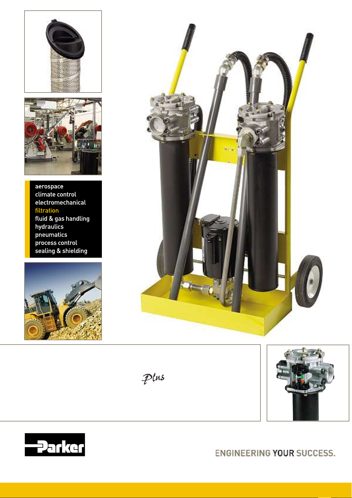
Maintenance Instructions
Turn switch to OFF position1.
and unplug cord from electri-
cal outlet.
Remove tube wands from oil to2.
prevent siphoning.
Loosen hex head screws on3.
lter cover. Turn cover to clear
screws, remove cover.
Pull lter element from the4.
lter head.
a) Replace the synthetic or
Microglass III elements.
Verify replacement.
b) Wire mesh elements
can be cleaned. Ultrasonic
cleaners provide best
results.
Install element in lter5.
housing. Make sure element
o-rings seat properly into the
head, making sure that the
notch on the element lines up
with the notch in the head.
Inspect the cover o-ring and6.
replace if necessary.
Replace cover and tighten7.
hex head screws until they are
snug. Do not over-torque these
screws. Do not interchange the
inlet lter cover with the outlet
lter cover. (e inlet lter has
a “RFP” prex, the outlet lter
has a “ILP” prex).
Assembly
Install hoses to inlet and outlet1.
lters by threading the hose
end with the straight thread
o-ring seal tting into the lter
ange.
Connect the PVC tube wands2.
to the swivel tting on the hose
end. When servicing the PVC
tube wand, do not over-torque
the metal ttings going into the
PVC coupling. Over-torque
will result in cracking the
coupling. Generally, 1/4 turn
beyond hand-tight is sucient.
Operating Instructions
Insert the inlet wand assembly1.
into the supply uid receptacle
(drum/reservoir). e RFP
lter is the inlet lter.
Insert the outlet wand assem-2.
bly into the clean uid recepta-
cle (drum/reservoir). e ILP
fIlter is the outlet lter.
AP@B%Ibg #7 L70 OQLO 0RV R71V
o11VMnNQV1g 0RQ1 Mok 2V1.N0 QL
V+mV11Q-V -om..M 72 52V11.2V o0
0RV 5.M5e
Verify that the ON/OFF switch3.
is OFF and plug the cord into
the proper grounded power
source (3 wire).
Turn switch to ON position and4.
check outlet wand for oil ow.
Allow 30 to 60 seconds for
lters to ll with oil. If repeated
attempts to obtain oil ow
fail, check pump inlet ttings
for tightness, remove inlet
lter access cover and verify
the cover sealing o-ring is in
place. For very viscous uids it
may be necessary to pour 1 or
2 quarts of uid into the RFP
inlet lter housing to prime
pump initially.
e condition of the lter5.
element should be monitored
by observing the cleanliness
indicator on the outlet lter.
When the indicator is in the
CHANGE position, both inlet
and outlet lter elements
MUST be replaced to prevent
uid from going through the
bypass in the lters.
e inlet lter element is6.
provided with a 0.2 bar bypass
spring, and prevents the pump
from cavitating if the element
is not changed. e outlet lter
element is provided with a 2.4
bar bypass spring to prevent
excessive pressure which may
be harmful to personnel or to
the lter cart.
3PFb%b*g <RV HN0V2 nk5o11
152QLS om01 o1 o2VNQVT -oN-V T72
0RV 5.M5e #7 L70 2V102Qm0 0RV
7.0NV0 R71V ,Q0R o1R.0f7TT -oN-V
,RQmR ,QNN lVTVo0 0RV T.Lm0Q7L
7T 0RV nk5o11 -oN-Vg mo.1QLS
V+mV11Q-V 52V11.2Vg ,RQmR Mok
nV Ro2MT.N 07 5V217LLVN 72 07 0RV
HN0V2 mo20e
e cleanliness indicator7.
works on dierential pressure
and will indicate the condi-
tion of the element (CLEAN,
CHANGE, or BYPASS).
WV6=g <RV HN0V2 mo20 M.10 nV
QL 75V2o0Q7L T72 0RV QLlQmo072 07
2Vol 5275V2Nke
Trouble Shooting
UFINe.d AP@D. 7Ie@B%Ib
Does not start ON/OFF Switch Turn switch ON, replace switch if defective
No electrical power Plug in cart
Defective motor Contact service department
No oil flow or erratic Filter housing not filled with oil Allow pump to run 30 to 60 seconds
pump noise Suction leak Check tightness of inlet fittings
Check o-ring in inlet filter cover for nicks
Kink or restriction in inlet hose
Add 1 or 2 quarts of oil to inlet filter
Defective pump Contact service department
Indicator reads Element dirty Replace or clean elements (both filters)
CHANGE or BYPASS Oil extremely cold or viscous Change element to coarser micron rating
Indicator does not No outlet element Install element
seem to move 40 micron element installed in Check cart model number to verify correct
outlet filter element. The inlet filter has a rating RFP
prefix; the outlet filter has an ILP prefix

7BPbJPFJ UFIJ@LBD 6PNe.
MOX;U 8.GePL.d.bB =e.d.bBD
MOX; 8.GePL.d.bB =e.d.bBD
VGB%Ib
\be.B
=e.d.bB
=e.d.bB VGB%IbD Ue@*
6_G.
8.GePL.d.bB
=e.d.bBD
\be.B [email protected]
MOX;UM-O7EMO9M5Z
940971Q
"K---$
`OO"&/9
BKEKBE?
"-O$OK
`caIaI?
`cJGDE?
BKEKBD?
40
ac
JeI
I
=kL0RV0Qm
ZQm27SNo11 ^^^
ZQm27SNo11 ^^^
ZQm27SNo11 ^^^
YQ02QNV
YQ02QNV
YQ02QNV
YQ02QNV
cea &o2
aeJ &o2
BJcDcK
`ccBGD
`ccBEJ?
`ccBGE
`caIaI?
BaEIDJ
"/&/""9
BKEJcc? ac ZQm27SNo11 ^^^ YQ02QNV aeJ &o2
BJcEKJ 9> 9o0V2 >VM7-oN YQ02QNV aeJ &o2
40
40
6
74
ac
9>
10
=0oQLNV11 =0VVN
=0oQLNV11 =0VVN
ZQm27SNo11 ^^^
=0oQLNV11 =0VVN
ZQm27SNo11 ^^^
9o0V2 >VM7-oN
ZQm27SNo11 ^^^
YQ02QNV
YQ02QNV
YQ02QNV
YQ02QNV
YQ02QNV
YQ02QNV
YQ02QNV
cea &o2
aeJ &o2
ac
40
10
a
ZQm27SNo11 ^^^
=kL0RV0Qm
ZQm27SNo11 ^^^
ZQm27SNo11 ^^^
YQ02QNV
YQ02QNV
YQ02QNV
YQ02QNV
cea &o2
aeJ &o2
UPFB [email protected]
X%LFIb 8PB%b*
X%LFIb 8PB%b*
X%LFIb 8PB%b*
X%LFIb 8PB%b*
X.J%P 6_G.
X.J%P 6_G.
X.J%P 6_G.
X.J%P 6_G.
7.Pe 6_G.
7.Pe 6_G.
7.Pe 6_G.
7.Pe 6_G.
\bB.*FPe C_GPDD
\bB.*FPe C_GPDD
MOX;U 8.GePL.d.bB \be.B =e.d.bBD
MOX; 8.GePL.d.bB \be.B =e.d.bBD
WIB.g B(. ,IeeI<%b* .e.d.bBD PF. ,IF B(. MOX; ;%eBFPB%Ib 6FIee._
MOX;U 1-O7E MO9 15Z "-O$OK "/&/""9
MOX;U 1-O7E MO9 1=58 "-O$OK "/&/""9
MOX;U 2-O7E MO9 1IND "-O$OK "/&/""9
bcZqWbJc=(bc?b;\
MOX;UM-O7EMO9M=58 bcZqWbJc=(bc?b!;>
MOX;UM-O7EMO9M\W? bcZqWbJc=(bc?b^Y#
Ordering Information
Y70V bA Wo20 L.MnV21 TVo0.2Vl ,Q0R n7Nl RQSRNQSR0Vl m7lV1 ,QNN VL1.2V op=0oLlo2l6 527l.m0 1VNVm0Q7L
Y70V aA (N0V2Lo0V lQ15NokVl 5o20 L.MnV2 1VNVm0Q7L ,QNN 2V4.Q2V k7. 07 m7L0om0 Wo2OV2 qQN02o0Q7L T72 o-oQNonQNQ0k
Y70V bA Wo20 L.MnV21 TVo0.2Vl ,Q0R n7Nl RQSRNQSR0Vl m7lV1 ,QNN VL1.2V op=0oLlo2l6 527l.m0 1VNVm0Q7L
Y70V aA (N0V2Lo0V lQ15NokVl 5o20 L.MnV2 1VNVm0Q7L ,QNN 2V4.Q2V k7. 07 m7L0om0 Wo2OV2 qQN02o0Q7L T72 o-oQNonQNQ0k

UPF!.F ^Pbb%Hba5ZTYBJR
^_JFP@e%L;%eB.F ?%>%D%Ib=@FIG.
AIbJ%B%Ib XIb%BIF%b*A.bBF.
<VNeA hJJ 3ci bDJa EGKaBB
!MoQNA m7LM7LQLT7)5o2OV2em7M
,,,e5o2OV2em7MdRTlV
%o0oN7S.V q#_&KEB;\ cbdaccB
87.2 N7moN o.0R72Q1Vl Wo2OV2 lQ102Qn.072
/accD Wo2OV2 _oLLQHL %72572o0Q7Le (NN 2QSR01 2V1V2-Vle
E= '5E=S #.noQ
<VNA hBEb JDbaEbcc
5o2OV2eMV)5o2OV2em7M
E8 'EF*.bB%bPS &.VL71 (Q2V1
<VNA hIJKKaEJJJbaB
E6 'E@DBF%PS 9QVLV2 YV.10ol0
<VNA hJK3ciaGaaaKIcbfc
5o2OV2eo.102Qo)5o2OV2em7M
E6 '=PDB.Fb =@FIG.S
9QVLV2 YV.10ol0
<VNA hJK3ciaGaaaKIcb BEc
5o2OV2eVo10V.275V)5o2OV2em7M
E5 'E@DBFPe%PS %o10NV _QNN
<VNA hGb3ciafBGKJEEEE
E0 'E].FNP%#PbS &oO.
<VNA hBBJ Ic aaKK JID
5o2OV2eojV2noQPoL)5o2OV2em7M
C=QY5'C.e*%@dS YQ-VNNV1
<VNA hKa3ciGE aDcBcc
5o2OV2enVNSQ.M)5o2OV2em7M
C8 'CFP]%eS %omR7VQ2QLRo >=
<VNA hIIIbKJEcBbJJ
C1 'C.ePF@DS ZQL1O
<VNA hKEI bE acBBKBB
5o2OV2enVNo2.1)5o2OV2em7M
AE 'APbPJPS ZQN07LgXL0o2Q7
<VNA hb BcIGBK Kccc
A^ '7<%B].FePbJS !07k
<VNA hJb3ci ab DabcaKc
5o2OV2e1,Q0jV2NoLl)5o2OV2em7M
AW 'A(%bPS =RoLSRoQ
<VNA hDGabIcKbaIaI
A0 'A].L( 8.G@Ne%LS \NVmoLk
<VNA hJac aDJcDK bbb
5o2OV2emjVmR2V5.nNQm)5o2OV2em7M
?= '`.FdPb_S \oo210
<VNA hJB3ciabKbJcbGc
5o2OV2eSV2MoLk)5o2OV2em7M
?Z '?.bdPF!S &oNNV2.5
<VNA hJI JK IG cJ cc
5o2OV2elVLMo2O)5o2OV2em7M
=7 '7GP%bS Zol2Ql
<VNA hKJBca KK cc cb
5o2OV2e15oQL)5o2OV2em7M
;\ ';%bePbJS :oL0oo
<VNA hKID3ciacEIK aIcc
5o2OV2eHLNoLl)5o2OV2em7M
;8 ';FPbL.S %7L0oMQLV1d(2-V
<VNA hKK 3ciJ Ic aI Dc aI
5o2OV2eT2oLmV)5o2OV2em7M
`8 '`F..L.S (0RVL1
<VNA hKcabc BKKGJIc
5o2OV2eS2VVmV)5o2OV2em7M
^Z '^Ib*ZIb*
<VNA hDIa aJaD DccD
^5 '^@b*PF_S &.lo5V10
<VNA hKGbaac JbII
5o2OV2eR.LSo2k)5o2OV2em7M
\= '\F.ePbJS #.nNQL
<VNA hKIK 3cib JGGGKEc
5o2OV2eQ2VNoLl)5o2OV2em7M
\W '\bJ%PS Z.MnoQ
<VNA hBbaaGIbK EcDbfDI
\6 '\BPe_S %721Qm73Z^i
<VNA hKBcaJIbBab
5o2OV2eQ0oNk)5o2OV2em7M
[U '[PGPbS <7Ok7
<VNA h3Dbi KGJcDKBcb
Z8 '7I@B( ZIF.PS =V7.N
<VNA hDaaIIB cJcc
Z0 'ZP]P!(DBPbS (NMo0k
<VNA hE EaEa IcIDcc
5o2OV2eVo10V.275V)5o2OV2em7M
Y4 'YPB>%PS >QSo
<VNA hKEb GEJI aGcb
5o2OV2eNo0-Qo)5o2OV2em7M
X2 'X.:%LIS (57lomo
<VNA hIaDbDbIGGccc
X1 'XPeP_D%PS =.noLS ]oko
<VNA hGcKIGKDbJEG
WY '6(. W.B(.FePbJDS
XNlVLjooN
<VNA hKb3ciIJbIDI ccc
5o2OV2eLN)5o2OV2em7M
WV 'WIF<P_S =OQ
<VNA hJEGJBbbccc
5o2OV2eL72,ok)5o2OV2em7M
W0 'W.< 0.PePbJS Z0 9VNNQLS07L
<VNA hGJBIEJ bEJJ
UY 'UIePbJS 9o21o,
<VNA hJD3ciaaIEK aJ cc
5o2OV2e57NoLl)5o2OV2em7M
U6 'UIFB@*PeS [Vmo lo WoNMVQ2o
<VNA hKIbaaBBB EKGc
5o2OV2e5720.SoN)5o2OV2em7M
8V '8IdPb%PS &.mRo2V10
<VNA hJcabaIa bKDa
5o2OV2e27MoLQo)5o2OV2em7M
85 '8@DD%PS Z71m7,
<VNA hE JBIGJIfabIG
5o2OV2e2.11Qo)5o2OV2em7M
7= '7<.J.bS =5$LSo
<VNA hJG3ciDIBEBIccc
5o2OV2e1,VlVL)5o2OV2em7M
7` '7%b*PGIF.
<VNA hGIGDDEGKcc
7Z '7eI>P!%PS &oL1O* &k102Qmo
<VNA hJab JDJbGa aIa
5o2OV2e1N7-oOQo)5o2OV2em7M
7Y '7eI>.b%PS Y7-7 ZV107
<VNA hKDG EKKE GGIc
5o2OV2e1N7-VLQo)5o2OV2em7M
6^ '6(P%ePbJS &oLSO7O
<VNA hGGa EbEDbJc
68 '6@F!._S ^10oLn.N
<VNA hBcabG JBBEcDb
5o2OV2e0.2OVk)5o2OV2em7M
63 '6P%<PbS <oQ5VQ
<VNA hDDG aaaBDDBDE
5E '5!FP%b.S \QV-
<VNhKDcJJJBJ aEKb
5o2OV2e.O2oQLV)5o2OV2em7M
5Z '5b%B.JZ%b*JIdS
9o2,QmO
<VNA hJJ3cibBaG KbEDED
5o2OV2e.O)5o2OV2em7M
57 '57ES %NV-VNoLl
<VNA hb abGDBG Kccc
4= '4.b.]@.ePS %o2omo1
<VNA hIDaba aKDIJaa
0E '7I@B( E,F%LPS
\VM507LWo2O
<VNA haE3cibb BGbcEcc
5o2OV2e17.0RoT2Qmo)5o2OV2em7M
Wo2OV2 972Nl,QlV
=@FIG.PbUFIJ@LB \b,IFdPB%IbA.bBF.
;F.. G(Ib.g OO $OOK&K&+/&-
a,FIdE6S C=SA^S A0S?=S ==S=7S ;\S;8S \=S
\6SU6S 7=S7ZS 5ZT

Guardian®
Portable Filtration System
182

183
The Guardian portable ltration system is a unique pump/motor/
lter combination designed for conditioning and transferring
petroleum-based and water emulsion uids. It protects your
system from contamination added with new uid because new
uid is not necessarily clean uid. Most new uids right out
of the drum are unt for use due to high initial concentrations
of contaminants. Contamination may be added to a new uid
during processing, mixing, handling, and storage.
The Guardian also circulates and “polishes” uid in your existing
systems to reduce the contamination to an acceptable level.
There are literally hundreds of applications that the Guardian is
suited for, with more being discovered each day. If your system
is sensitive to the harmful effects of contamination, then the
Guardian may be ideal for you.
Ground Support
Hydraulic Service
Mining

184
Mobile
Industrial
Marine
Features Advantages Benefits
Lightweight, hand held,
compact design (less
than 24 Ibs 16” X 8” ap-
proximate foot print).
Easy to carry and fits
easily on top of 55
gallon drums.
One person
operation, capable of
getting to hard to reach
areas.
Flow rate to 4 gpm. Filters and transfers
simultaneously.
One step operation.
Powerful pump/motor
combination with Car-
boxylated Nitrile seals
standard.
Handles fluids up to
16,000 SUS viscosity
(11,000 SUS -24 VDC).
Reliable performance in
a wide variety of
operating conditions.
Built-in relief valve with
no downstream fluid
bypass.
Only filtered fluid
reaches downstream
components.
100% filtration ensured,
even when unattended.
Wide variety of filter
elements available.
High capacity 2 micron
absolute disposable
microglass to 74
micron cleanable wire
and water removal.
Maximizes
element life
between changes.
Clear, wire-reinforced 5’
hose assemblies with
wand attachments.
No additional hardware
required.
Ready to use and easy
to maneuver.
Optional quick
disconnect hose
connections.
Fast, easy setup and
tear-down.
Eliminates messy drips.
Heavy-duty ¼ HP,
115 VAC (230 VAC, 24
VDC- optional) motor
with thermal overload
protection.
UL recognized and CSA
listed, with replaceable
brushes.
Safe, reliable
performance; field
serviceable.
Geroter pump with
visible serviceable inlet
strainer.
Dirt tolerant design with
added protection.
Pump reliability in highly
contaminated fluids.
Quiet operation. Less than 70dB noise
level @ 3 feet.
Can be used most
anywhere with
minimal disturbance.
Convenient
inlet-to-outlet hose
connection.
Contains fluids when
transporting.
Clean and safe
operation.
Low center of
gravity.
Guardian stability. Unattended
reliability.
Dual motor seals. Added motor protection. Longer motor life.
Auxiliary inlet/outlet
ports.
Used in place of, or in
addition to, standard
ports. The outlet can
also be used as a
sampling port.
Flexibility.

185
Maximum Allowable Operating
Pressure (MAOP): 50 psi (3.4
bar)
Flow Capacity: Up to 4 gpm
(15 lpm)
Maximum Recommended Fluid
Viscosity: (.85 specic gravity)
110-120 VAC and
220-240 VAC 16,000 SUS
24VDC 11,000 SUS
Warning: Explosion hazard. Do
not pump ammable liquids such
as gasoline, alcohol, solvents, etc.
Operating Temperatures:
Unit: -15°F to 180°F (-26°C to
82°C)
Wand/Hose: 25°F to 120°F
(-4°C to 49°C)
Visual Indicator: Differential
pressure type, set at 25 psid
Recommended Fluids: petroleum
based oils, water emulsions, and
diesel fuels
Integral Relief Valve: set at 50 psi
for motor protection.
Noise Level: <70db at 3 ft.
Guardian Series
Installation and Specification Data
Electrical Motor: ¼ hp@2500 rpm.
24 VDC; 10A max.
110-120 VAC; 50/60 Hz; 3A max.
220-240 VAC; 50/60 Hz; 1.5A max.
Thermal overload protected.
Replaceable brushes (500 hours).
Weight: approximately 23 lbs. 5 oz.
Materials:
Housing: cast aluminum
Cover: die cast aluminum
Handle and Indicator: nylon
Wands and Hose: PVC
Fittings: brass
Seals: uorocarbon/
carboxylated nitrile
18/3 power cord with
3 prong plug. 1 ft.
length(110/120 VAC).
3 wire (1.5mm2cross section)
power cord, 3 ft. lenth
(220/240 VAC).
Quick access, zero
leakage, ¾-11.5 NH
garden hose connections.
Non conductive
carrying handle. Minimum
Element removal clearance.
Removable element.
139.7
5.50
Vibration isolating rubber
feet 4-pls.
¾”wire reinforced flexible
inlet hose, 5 ft. length. ¾”wire reinforced flexible
outlet hose, 5 ft. length.
¾”- 11.5 NH
garden hose
thread(Outlet).
25 PSI differential
visual indicator.
208.5
8.21
¾” lightweight
wand assembly,
3 ft. full extended
length.
#10-24 Terminal Studs
2-places (24 VDC)
On/off
switch
50.8
2.00
152.4
6.00
Alternate customer exchangeable, ½-14 NPT
inlet and outlet locations (Plugged).
Inlet
Outlet
195
7.68
Motor is UL recognized
and CSA listed
398.5
15.69
Visible and easily
cleanable inlet strainer
Clean inlet strainer as required
Linear Measure: millimeter
inch
Guardian Schematic

186
Media
Code
New Oil ISO ISO Achieved Element Life Elements Used
per 250 gallons
10C 22/20/16 21/19/15 120 gallons 2.08
20Q 22/20/16 21/19/15 486 gallons .51
10Q 22/20/16 19/16/14 407 gallons .61
05Q 22/20/16 17/15/12 330 gallons .75
02Q 22/20/16 15/13/10 316 gallons .79
Mining
Note 1: Guardian not
recommended for fluid
viscosities greater than
16,000 SUS
(11,000 SUS;24VDC)
Note 2: Flows based
on Guardian with no
element installed
Bx = 2 50.0%
Bx = 20 95.0%
Bx = 75 98.7%
Bx = 200 99.5%
Bx = 1000 99.9%
Efficiency
Beta at x
Rating Particle Size
Guardian Flow vs. Viscosity Performance
Multipass test run at 4 gpm to 35 psid
1Reference ratings only. Not multipass tested due to coarseness.
* Not applicable
Estimated Guardian Element Life and Cleanliness Levels
The following chart shows typical element life
(in gallons of oil passed) and cleanliness levels
achieved by standard Parker elements available with the
Guardian. Some assumptions have been made.*
* 1. New oil is at ISO 22/20/16.
2. No environment or work ingression.
3. Single pass oil transfer.
NOTE: Data for fluid transfer only. For continuous fluid
polishing, lower ISO cleanliness levels will be achieved.
100000
10000
10
1000
100
0 1 2 3 4 5
Viscosity (SUS)
Flow (GPM)
Media
Code
Filter
Media
Time Averaged
Beta x/y/z =2/20/75
Where x/y/z is:
Dirt
Capacity
(Grams)
74W Woven Wire 74 micron1*
40W Woven Wire 40 micron1*
25W Woven Wire 25 micron1*
20C Cellulose 20 micron1*
10C Cellulose 5/8/16 4
20Q Microglass III 7.1/13.7/17.3 16.2
10Q Microglass III 2.7/7.3/10.3 14.4
05Q Microglass III <2/2.1/4.0 14.9
02Q Microglass III <2/<2/<2 14.3
Guardian Series
Element Performance

187
Guardian Operation
A. Remove all shipping plugs from the hoses and ttings.
B. Connect the inlet and outlet hose assemblies to the unit.
C. Connect the wand assemblies, if required.
D. Place the inlet hose wand assembly into the uid to be
ltered and/or transferred.
E. Place the outlet hose/wand assembly into the container
where the uid discharge is desired.
F. Plug in the unit.
G. Flip the switch on the end of the unit to the “on” posi-
tion.
NOTE: For no-mess transportation, the inlet and outlet
hose assemblies can be screwed together by
removing the wand assembly.
Guardian Element Servicing
A. Flip the switch on the end of the unit to the “off” position
and disconnect the electrical plug.
B. Rotate the cover counter-clockwise and remove.
C. Remove the element from the housing. Discard all
disposable elements. These elements are not cleanable,
D. Place the new element In the housing, tting the o-ring
neck into the large hole at the bottom.
E. Inspect the cover o-ring and replace if necessary.
F. Replace the cover and hand-tighten.
NOTE 1: It is recommended that the Guardian be
cleaned and ushed between uses with
dissimilar uids to prevent uid mixing.
NOTE 2: Motor brushes may require changeout
every 500 service hours
Problem Cause Solution
Does not start. ON/OFF switch.
No electrical power.
Rectier.
Motor overheats (160°F).
Defective motor.
Turn switch on, replace switch if defective.
Plug in Guradian, check for tripped circuit breakers, check for
blown fuses.
Replace if defective.
Allow motor to cool, thernal overload will automatically reset.
Replace motor.
Does not start or errattic
motor noise.
Worn motor brushes. Replace motor brushes.
Intermittent start.stop oera-
tion.
High viscosity uids.
Worn motor brushes.
Defective motor.
High viscosity uids can cause the motor to overheat and cycle
intermittently.
Replace motor grushes.
Replace motor.
Hot motor. Pumping under heavy load.
Defective motor.
It is normal, under a heavy pumping load for the motor to reach
160°F.
Replace motor if shell temperature reaches greater than 170°F.
No ow or erratic pump
noise.
Filter housing not lled with oil.
Suction leak.
Obstructed outlet.
Element dirty.
Sheared pump key.
Defective Guardian.
Allow Guardian to run a few seconds.
Check tghtness of inlet ttings and hoses. Check gaskets are
in place and are not damaged. Kink or restriction in the inlet
hose.
Clear outlet.
Replace or clean element.
Replace woodruff key.
Replace unit.
No ow, erratic pump noise,
motor overheats.
Gears binding. Disassemble Guardian and throroughly clean the gear set.
Always use the inlet strainer provided to protect the unit.
Replace defective gears.
No suction. Plugged strainer. Clean or replace the inlet strainer as required.
Clean relief valve. Check for damaged internal o-rings.
Reduced oil ow. High viscosity uids.
Element dirty.
Relief valve sticks or is lodged
open.
Partially obstructed inlet or
outlet hose.
Suction leak.
Worn gears.
High viscosity uids can cause reduced ow, which is normal.
Replace or clean element.
Clean releif valve or replace if defective.
Clear the hose obstruction.
Check tightness of inlet ttings and hose.
Replace gear set.
Indicator moves to RED
Area.
Element dirty.
Oil extremely cold or viscous.
Obstruced outlet.
Defective indicator.
Replace or clean element.
Change element to coarser micron rating.
Clear outlet obstruction.
Replace indicator.
Indicator dows not seem to
move.
No element.
Defective indicator.
Install element.
Replace indicator.
Joses discolor or are hard. Fluid compatibility. Certain uids, over time, will cause the hoses to discolor. This
does not impair their performance. But, some uids will cause
the hoses to become brittle, requiring replacement.
Oil formation under unit. Defective shaft seal. Replace the motor shaft seal.
Troubleshooting Guide

188
Replacement Elements
Media Part No. Box Qty.
02Q 933467Q 2
05Q 932018Q 2
10Q 932017Q 2
20Q 933468Q 2
10C 932016 2
20C 932020 2
25W 922627 1
40W 922628 1
74W 922626 1
WR 932019 2
Parts List
1. Label. . . . . . . . . . . . . . Consult Factory
2. Motor, 110-120 VAC . . . . . . . . .931913
220-440 VAC. . . . . . . . . .932381
24 VDC. . . . . . . . . . . . . . .932759
3. SHCS(4),¼-20x1 . . . . . . . . . . . .902734
4. Adapter Plate . . . . . . . . . . . . . .931890
5. Housing O-Ring . . . . . . . . . . . .V72041
6. Polypak Seal . . . . . . . . . . . . . . .931921
7. Shadow Plate . . . . . . . . . . . . . .931899
8. Woodruff Key 1
/8 x 3/8. . . . . . . . .931877
9. SHCS(4), ¼-20 x¾ . . . . . . . . . .902679
10. Roll Pin 1
/8 x ¾ . . . . . . . . . . . . . .903630
11. Geroter Set . . . . . . . . . . . . . . . .931873
12. Geroter Ring . . . . . . . . . . . . . . .931903
13. Outlet Plate . . . . . . . . . . . . . . . .931900
14. Geroter O-ring . . . . . . . . . . . . .V72135
15. Brass Pipe Plug (2) ½-14. . . . .931920
16. RoIl Pin 1
/8 x 5/8. . . . . . . . . . . . .903426
17. SHCS (2), ¼-20 x 5/8. . . . . . . . .931889
18. Handle . . . . . . . . . . . . . . . . . . . .931897
19. Cover . . . . . . . . . . . . . . . . . . . . .931892
20. Cover O-Ring. . . . . . . . . . . . . . .V72237
21. Element . . . . . . . . . . . . . . . . . . . . . . . . .
22. Relief Valve . . . . . . . . . . . . . . . .928981
23. Indicator Kit. . . . . . . . . . . . . . . .927422
24. Housing . . . . . . . . . . . . . . . . . . .931838
25. Rubber Bumpers (2) . . . . . . . .931888
26. SHCS(2), ¼-20 x ½ . . . . . . . . . .902907
27. Brass Fitting (2) . . . . . . . . . . . .931928
28. Gasket (4). . . . . . . . . . . . . . . . . .931956
29. Inlet Screen. . . . . . . . . . . . . . . .931927
30. Inlet Hose Assembly . . . . . . . .931936
31. Outlet Hose Assembly . . . . . . .931937
32. Wand Crevice Assembly . . . . .931965
33. Wand Adapter Assembly . . . . .931966
34. Washer (2) . . . . . . . . . . . . . . . . .926106
35. Quick Disconnect Kit . . . . . . . .932097
(Not Shown)
36. Washer. . . . . . . . . . . . . . . . . . . .932085
37. Brush Kit (110/120) . . . . . . . . .934329
(220/240 VAC) . . . . .934327
(24 VDC) . . . . . . . . . .932761
Seal Kit . . . . . . . . . . . . . . . . . . . . . .932263
Bowl Extension Kit . . . . . . . . . . . .932081
NOTE: SHCS denotes “socket head cap screw”
Guardian Replacement Parts

189
Please note the bolded options reflect
standard options with a reduced lead-
time. Consult factory on all other lead-
time options.
Select the desired symbol (in the correct position) to construct a model code.
Example:
BOX 1 BOX 2 BOX 3 BOX 4
GT4 10C 1
BOX 1: Seals
Symbol Description
None Carboxylated Nitrile
(Standard)
Note: Consult factory for uids not
compatible with uorocarbon.
BOX 3: Media
Symbol Description
74W Wire Mesh
40W Wire Mesh
25W Wire Mesh
10C Cellulose
20Q Microglass III
10Q Microglass III
05Q Microglass III
02Q Microglass III
WR Water Removal
BOX 2: Model
Symbol Description
GT4 Guardian®110/120 VAC
GT4D 24VDC
GT4E 220/240 VAC
BOX 4: Options
Symbol Description
1 None
6 Quick disconnect hose
connections
Guardian Series
How to Order
Global products as identified are offered
worldwide through all Parker locations and
utilize a common ordering code.
This manual suits for next models
3
Table of contents
Popular Outdoor Cart manuals by other brands

Rock-N-Roller
Rock-N-Roller MULTI-CART R2RT quick start guide

HAMPTON BAY
HAMPTON BAY GO-11063-AAR Use and care guide

Gardeners
Gardeners 8594333 quick start guide

Rittal
Rittal 4051.050 Assembly and operating instructions

Gorilla Carts
Gorilla Carts GOR200B-T owner's manual

Wenger
Wenger Gearboss owner's manual

Cambro
Cambro CVC75 owner's manual

Techni Mobili
Techni Mobili RTA-SIB006 Assembly instruction

Martha Stewart
Martha Stewart Lionel Assembly instructions

Evocare
Evocare Medication Cart user manual

Southern Enterprises
Southern Enterprises RIATA BAR CART Assembly instructions

AllFitHD
AllFitHD AF-1250SS1 manual