4 5
WORK AREA
• ALWAYS use in a well ventilated area.
• ALWAYS position the exhaust outlet away from people.
• NEVER use indoors or in a confined space.
• READ these safety instructions before using the equipment.
• KEEP CHILDREN AWAY FROM THE GENERATOR
POSITIONING THE GENERATOR
• ALWAYS leave a least a 1M gap between the generator and any
surrounding building or structures.
• ALWAYS ensure the generator is on a solid, flat surface.
• ALWAYS ensure the surrounding area is free from any material
that could burn or be damaged by heat.
• NEVER move or tilt the generator whilst it is switched on.
FIRE PREVENTION
• ALWAYS switch the engine OFF when refuelling.
• ALWAYS refuel away from any source of heat.
• ALWAYS refuel in a well ventilated area.
• NEVER overfill the tank, fill to the level specified
(See “Check fuel level” on page 13.).
• NEVER smoke whilst refuelling and avoid smoking or using a
naked flame near the generator.
• NEVER start the engine if there is spilled fuel. Any spillage must
be wiped clean and the generator allowed to dry before
attempting to start the engine.
PREVENTION OF ELECTRIC SHOCK
• NEVER use the generator in wet conditions unless it is well
protected/covered. Under these conditions, adequate ventilation
MUST be provided.
• NEVER operate the generator with wet hands.
• NEVER use water or any other liquids to clean the generator.
• NEVER allow the generator air vents to become blocked.
ADDITIONAL SAFETY RULES FOR GENERATORS
• ALWAYS ensure the applied load does not exceed the generator
rating. Overloading the generator is dangerous and could cause
serious damage.
• ALWAYS disconnect the generator when carrying out any
maintenance.
• ALWAYS ensure the generator reaches operating speed before
connecting a load.
• NEVER allow the generator to run out of fuel when a load is
connected.
• NEVER transport the generator with fuel in the tank.
• DO NOT connect to a commercial or residential power supply;
e.g. ring main.
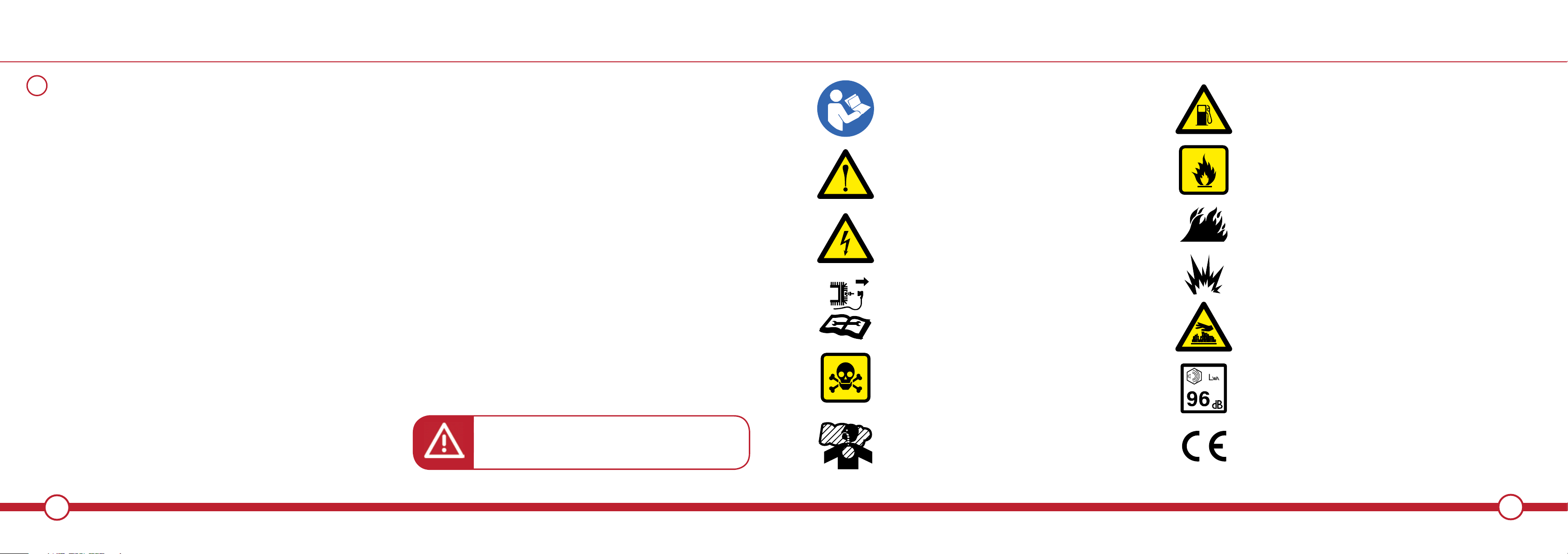
SAFETY SYMBOLS
GENERAL SAFETY RULES
WARNING! Exhaust fumes can be extremely
dangerous if inhaled.
i
WARNING - To reduce the risk of injury,
user must read instruction manual.
This symbol, before a safety comment, indicates a
PRECAUTION, a WARNING or a DANGER. Ignoring
this warning can lead to an accident for yourself or for
others. To limit the risk of injury, fire, or electrocution
always apply the recommendations indicated.
EXPLOSION HAZARD
DANGEROUS VOLTAGE
FLAMMABLE
HOT SURFACES WILL BURN FINGERS OR PALMS
REMOVE SPARK PLUG LEAD BEFORE MAINTENANCE
WARNING! Exhaust gas contains toxic substances.
Do not run the engine in closed or poorly ventilated areas.
GUARANTEED SOUND POWER LEVEL
CONFORMS TO CURRENT SAFETY STANDARDS
POISONOUS FUMES Do not use the generator in an
enclosed space.
DANGER! Petroleum spirit is highly flammable.
No smoking or naked light.
RISK OF FIRE Do not add fuel when operating.