8
diytube Stereo 35 Rev E PCB Parts Revised: 8/12/2013
Tip: Put a dot in the checkbox if you have the part already as a quick
reference when ordering parts. X out the checkbox when you have installed
the part on the PCB.
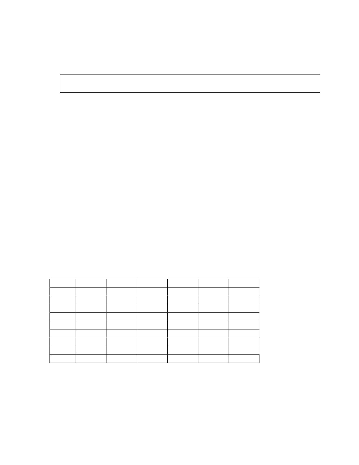
Item QTY Reference Part Mouser Part Cost
______________________________________________________________________
2 R1,R2 47.5k, 1/2W 71-RN60D-F-47.5K 0.11
6 R3,R4,R13,R14, 475k, 1/2W 71-RN60D-F-475K 0.11
R15,R16
6 R5,R6,R18, 1k, 1/2W 71-RN60D-F-1.0K 0.11
R21,R24,R27
2 R7,R8 300k, 2W 594-5083NW300K0J 0.10
2 R9,R10 27k, 1W 281-27K-RC 0.13
2 R11,R12 33k, 1W 281-33K-RC 0.13
4 R17,R20,R23,R26 470, 2W 594-5083NW470R0J 0.10
4 R19,R22,R25,R28 10K Pot 72-T93YB-10K 1.58
1 R29 360k, 2W 594-5083NW360K0J 0.10
2 R30,R31 100K Pot 72-T93YB-100K 1.33
1 R33 6.8k, 2W 594-5083NW6K800J 0.10
4 R34,R35,R40,R41 100, 2W 594-5083NW100R0J 0.10
2 R38,R39 150k, 1/2W 71-RN60D-F-150K 0.11
1 R42 Inrush Limiter 527-CL90 2.21
4 R43,R44,R45,R46 10 Ohm, 1/4W 71-RN55D-F-10 0.10
4 R47,R48,R49,R50 1k, 1/4W 71-RN55D-F-1.0K 0.11
4 R51,R52,R53,R54 100, 1/4W 71-RN55D-F-100 0.11
4 C1,C2,C3,C4 0.1uF,400V 75-715P400V0.1 3.61
4 C5,C6,C7,C8 470uF,35V 5mmLS 647-UVR1V471MPD 0.69
4 C9,C10,C11,C12 120uF 5985-380-450V121 3.57
2 C16,C17 27pF 140-500N5-270J-RC 0.10
2 C18,C19 33pF 140-500N5-330J-RC 0.14
2 C20,C21 18pF 140-500N5-180J-RC 0.11
2 C22,C23 0.22uF 5989-250V.22-F 0.68
2 D1,D2 UF4007 Diode 625-UF4007-E3 0.19
1 J1 10pin .375 Block 571-114376644 5.23
4 J2,J3,J4,J5 3pin .375 Block 571-14376645 1.47
2 J6,J7 2pin 5.08MM conn 571-282837-2 0.40