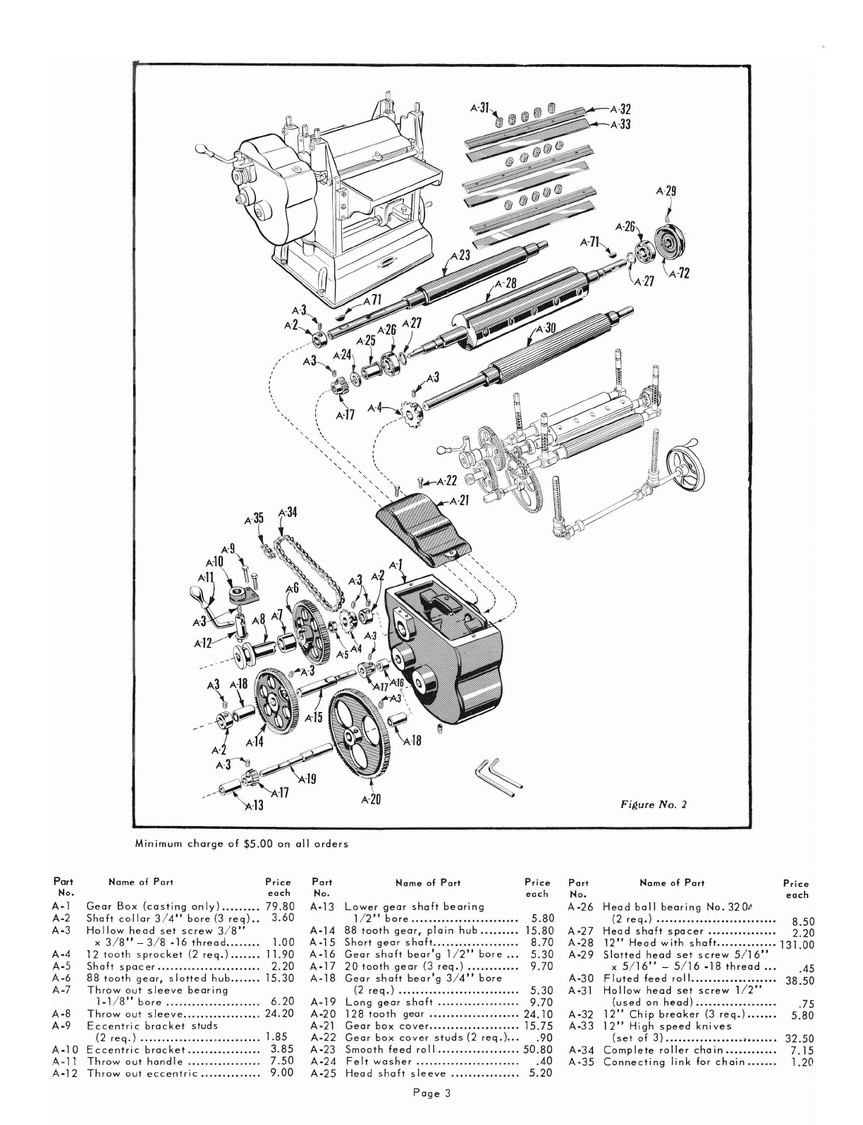
manuals.online logo
Brands
  1. Home
  2. •
  3. Brands
  4. •
  5. Parks
  6. •
  7. Industrial Equipment
  8. •
  9. Parks 12 Use and care manual

Parks 12 Use and care manual

OPERATING
INSTRUCTIONS
AND
PARTS
LIST
FOR
PARKS
12"
THICKNESS
PLANER
IMPORT
ANT:
This
list
is
valuable. It
will
enable you
to
secure
prompt
service on
replacement
parts
and
avoid unnecessary
correspondence
with our factory.
We
suggest
that
you keep
it
filed away with
other
valuable papers.
THE
PARKS
WOODWORKING
MACHINE
COMPANY
Manufacturer~
of
Quality
Woodworking
Machines
Since
1887
Cincinnati,
Ohio
45223
Apr. 1, 1975
Instructions
For
Operation
and Maintenance
of
12
11
The PARKS THICKNESS PLANER
Figure
No.
J
Your
Parks
12"
Planer
is
shipped
complete
(without
motor)
in.
one
crate.
Adjustments
are
made
at
the
factory.
It
need
only
be
connected
to
a
motor
to
start
using.
Motor and Pulley Recommendations
Planer
is
designed
to
be
used
with
a
110/220
volt,
60
cycle
single
phase,
or
a
220/440
volt,
60
cycle
three
phase
motor.
A 1
h.p.
motor
is
recommended
for
light
duty,
and
a 2
h.p.
for
heavy
duty.
When
a 1750
RPM
motor
is
used,
a
7"
pulley
should
be
used
on
the
motor
shaft
to
obtain
the
proper
RPM
(4000
to
4200)
at
the
cutterhead.
If
a
3450
RPM
motor
is
used,
a
4"
pulley
should
be
used.
Use
of
double
grooved
pulleys
and
belts
is
advisable,
when
heavy
work
is
required.
Lubrication
Your
Planer
is
a
precision
built
machine
and
should
be
given
the
best
of
care.
If
kept
clean
and
properly
lubricated,
it
will
give
many
years
of
trouble
free
service.
The
gear
box
should
be
lubricated
with
1/.
to
1
pound
of
soft
pressure
gun
grease
obtainable
at
gasoline
service
stations.
The
ball
bearings
are
grease
packed
at
the
factory
and
are
alemite
fitted.
We
suggest
lubricating
about
twice
a
year.
Table
roll
bearings
and
feed
roll
bearings
should
be
oiled
each
day
if
the
Planer
is
used
continuously.
Automobile
engine
oil
S.A.E.
30
is
recommended.
Adjustments
If
it
becomes
necessary
to
re-set
the
feed
rolls
or
pressure
bar,
these
steps
should
be
followed
(Be
sure
Planer
is
not
running):
I-Place
a
board
on
each
side
of
the
Planer
table
and
raise
the
table
until
the
knives
are
touching
the
boards.
2-Lower
the
two
feed
rolls
and
pressure
bar
until
they
also
touch
the
two
boards.
The
feed
rolls,
knives
and
pressure
bar
should
now
be
even
and
parallel.
3-Remove
the
boards
and
lower
the
fluted
in-feed
roll
%
turn
of
the
adjusting
studs.
Lower
the
smooth
out-feed
roll
1/.
turn.
4-When
the
pressure
bar
is
set
too
low
it
will
prevent
the
board
from
following
through.
It
will
then
be
necessary
to
raise
the
bar
slightly.
Page
2
5-For
finish
work
be
sure
the
table
rolls
are
not
more
than
1/64"
above
the
table
at
all
times.
Capacity
This
machine
will
plane
material
up
to
12
inches
wide
by
4
inches
thick.
Maximum
cut
is
YB
inch.
It
will
take
pieces
as
short
as
6
inches
and
as
thin
as
1/16".
Resetting Planer Knives
The
knives
can
be
set
in
the
following
manner:
~fter
they
have
been
reground
and
are
uniform,
they
can
be
reset
tn
the
head
fairly
accurately
by
placing
a
shim
under
the
length
of
each
knife
in
the
bottom
of
the
slot
in
the
head.
These
shims
can
be
pieces
of
wire
12"
long
and
small
in
diameter.
The
thick-
ness
corresponds
more
or
less
to
the
amount
of
stock
removed
from
the
knife
in
regrinding.
The
other
method
consists
of
setting
the
individual
knives
to
the
table
of
the
machine.
This
can
be
done
by
having
the
set
screws
that
lock
the
gib
against
the
knives,
drawn
up
just
firm
enough
to
hold
the
knives.
This
is
done
on
all
three
knives.
Then
you
place
two
pieces
of
hard
wood
of
uniform
thickness
on
the
table
at
either
end
of
the
head.
Thp.
table
is
then
raised
so
that
the
knife
which
is
set
farthest
out
of
the
head,
is
just
scraping
the
wood.
The
other
knives
are
then
raised
to
the
level
of
the
highest
knife.
This
can
be
done
by
tapping
lightly
with
something
similar
to
a
center
punch
at
the
base
of
the
knives
on
either
side
of
the
head.
Be
sure
and
lock
the
knives
securely
before
running
the
machine.
If
an
indicator
on
a
stand
is
available,
a
third
method
may
be
used.
This
consists
of
setting
the
indicator
point
directly
above
the
highest
part
of
the
cutting
circle
of
the
knives
on
the
top
of
the
head.
Take
a
reading
on
one
end
of
the
knife
and
raise
the
other
end
of
the
knife
to
indicate
the
same.
The
other
two
knives
should
be
tapped
up
to
the
same
reading.
Be
sure
and
lock
all
knives
securely.
Instructions For Ordering Parts
All
parts
Illustrated
in
FIgures
No.2
and
No.3
and
listed
on
the
following
pages
under
part
numbers
can
be
ordered
from
the
fac-
tory.
Screws,
nuts,
washers,
etc.,
are
standard
items
and
may
be
purchased
locally
by
noting
the
specifications
listed
for
these
parts.
All
prIces
are
suhJect
to
change
WIthout
notIce.
Figure
No.2
Minimum
charge
of
$5.00
on
all
orders
Part
Name
of
Part
Price
Part
Name
of
Part
Price
Part
Name
of
Part
Price
No.
each
No.
each
No.
each
A-l
Gear
Box
{casting
only)
..••.••.•
79.80
A-J3
Lower
gear
shaft
bearing
A
-26
Head
ball
bearing
No.
320"
A-2
Shaft
collar
3/4"
bore
(3
req)
..
3.60
1/2"
bore
...•••.••.••••.••••.•.•..
5.80
(2
req.)
.....••..•••••.••••••..•.•.•
8.50
A-3
Hollow
head
set
screw
3/8"
A-14
88
tooth
gear,
plain
hub
••.••..••
15.80
A-27
Head
shaft
spacer
.••••.•••.••.•.•
2.20
x
3/8"
-
3/8
-16
thread
.•.•.•.•
1.00
A-15
Short
gear
shaft
•..•••...•......•.•.
8.70
A-28
12"
Head
with
shaft
•••••••.••••••
131.00
A-4
12
tooth
sprocket
(2
req.)
.
11.90
A-16
Gear
shaft
bear'g
1/2"
bore
•.•
5.30
A-29
Slotted
head
set
screw
5/16"
A-5
Shaft
spacer
................•.......
2.20
A-17
20
tooth
gear
(3
req.)
••.•••.•••••
9.70
x
5/16"
-
5/16
-18
thread
...
.45
A-6
88
tooth
gear,
slotted
hub
.
15.30
A-18
Gear
shaft
bear'g
3/4"
bore
A-30
Fluted
feed
roil
••.••.••.•••.•••••••
38.50
A-7
Throw
out
sleeve
bearing
(2
req.)
••••........•..........••..•
5.30
A-31
Hollow
head
set
screw
1/2"
1-1/8"
bore
.............•......•.
6.20
A-19
Long
gear
shaft
..••..•••••.•••.•..
9.70
(used
on
head)
.•.........•••.•.••
.75
A-8
Throw
out
sleeve
...............••.
24.20
A-20
128
tooth
gear
.•.••••.•...•..•••.••
24.10
A-32
12"
Chip
breaker
{3
req.).......
5.80
A-9 E
ccentri
c
brocket
studs
A-21
Gear
box
cover
..••.••.••.•.••••.•••
15.75
A-33
12"
High
speed
knives
(2
req.)
...•..•..•••.•••.•..••..•...
1.85
A-22
Gear
box
cover
studs
(2
req.)...
.90
(set
of 3)
..••.••••.••.•.•••••••••••
32.50
A-10
Eccentric
brocket
..••.•••.••..•...
3.85
A-23
Smooth
feed
roil
•••.•.•.•.•...••..•
50.80
A-34
Complete
roller
chain
•.••••.•.••.
7.15
A-11
Throw
out
handle
7.50
A-24
Felt
washer
••••••.••..••••••..••••.
.40
A-35
Connecting
link
for
chain
.
1.20
A-12
Throw
out
eccentric
.•..•..•.•..•.
9.00
A-25
Head
shaft
sleeve
•.•••••••....•••
5.20
Page
3
k43
k61
·60
Figure
No.3
Part
Name
of
Part
Price
Part
Name
of
Part
Price
Part
Name of
Part
Price
each
each
No.
each
No.
No.
A.36
Pressure
bar
19.25
A·49
5/8"
hex
nut
1"
long A-59
Left
side
costing
86.90
A.37
Hood
stud
(2
req.l..
1.75
3/8
-16
thread
3.85
A-60
Right
side
costing
86.90
A-38
Shoving
hood
28.80
A-50
Spring
collar
(6
req.)
1.45
A-61
Bose
54.50
A-39
Lock
nut
for
hood
.75
A-51
Compression
spring
(6
req.)
3.85
A-62
Elevating
shaft
5.50
A.40
Adjusting
stud
for
hood
1.40
A·52
Roll
bearing
stud
(4
req.)
3.30
A·63
Shaft
collar
5/8"
(4
req.)
2.65
A-41
Table
roller
(2
req.)
11.00
A-53
Pressure
bar
stud
(2
req.)
4.40
A-64
Bevel
gear
L102
(4
req.)
8.75
A-42
Table
roll
bearing
(4
req.)
5.80
A-54
Smooth
feed
roll
bearing
A-65
Elevating
screw
(2
req.
-
A.43
Table
139.00
(2
req.
-
specify
r
or
I)
7.00
specify
right
or
left)
4.60
A.44
Table
gib
(2
req.)
5.00
A-55
Stud
collar
(2
req.)
1.50
A-66
Column
tie
rod
(2
req.)
5.70
A-45
Lock
nut
for
table
gib............
.75
A-56
Fluted
feed
roll
bearing
A-67
Hand
wheel
and
handle
15.40
A-46
Locknut
stud
75
(2req.-specify
ror
I)
8.25
A-68
Depth
indicator
1.00
A-47
Table
roller
adjusting
stud.....
.65
A.57
Bearing
cop
studs
(2
req.)
1.20
A-69
Depth
scale
1.20
A-48
Lock
nut
for
table
roller.........
.75
A.58
Bearing
cop
11.45
A·70
1/4"
oiler
(4
req.)................
.75
(specify
right
or
left)
The
following
ports
shown
on
figures
2
and
3
are
standard
and
can
be
purchased
locally
A-71
Half
moon key
3/16"
.35
A·74
3/8"
x
11/16"
jam
nut
3116"
A·76
Hex
nuts
1/2"
x
5/16"
x
7/8"
A.72
3"
V
pulley
3/4"
bore
5.75
thick
3/8
.16
thread
.50
1/2
-13
thread
1.20
A.73
3/8"
x
11/16"
jam
nut
5116"
A-75
Hex
head
bolts
112"x
1-3/4"
A-77
Alemite
fitting
.65
thick
3/8
.16
thread
.50
1/2
-13
thread
1.20
Page
4

Popular Industrial Equipment manuals by other brands

PCB Piezotronics IMI SENSORS 691A51/01 Installation and operating manual

PCB Piezotronics

PCB Piezotronics IMI SENSORS 691A51/01 Installation and operating manual

GAP Geysers Eco Max Homeowner's manual

GAP

GAP Geysers Eco Max Homeowner's manual

Sesino AP EMX Series Use and maintenance manual

Sesino

Sesino AP EMX Series Use and maintenance manual

BVA Hydraulics FT108 instruction manual

BVA Hydraulics

BVA Hydraulics FT108 instruction manual

Rodix FEEDER CUBE VF Series manual

Rodix

Rodix FEEDER CUBE VF Series manual

Mitsubishi Electric MR-JET-G user manual

Mitsubishi Electric

Mitsubishi Electric MR-JET-G user manual

Siemens simatic c7-621 manual

Siemens

Siemens simatic c7-621 manual

Graco ProMix PD2K Repair parts manual

Graco

Graco ProMix PD2K Repair parts manual

Bühler technologies GAS 222.35U Brief instructions

Bühler technologies

Bühler technologies GAS 222.35U Brief instructions

ABB HT595228 Operation manual

ABB

ABB HT595228 Operation manual

Pfeiffer Vacuum TTR 101 operating instructions

Pfeiffer Vacuum

Pfeiffer Vacuum TTR 101 operating instructions

Donaldson Torit RWB-2000 Installation and operation manual

Donaldson Torit

Donaldson Torit RWB-2000 Installation and operation manual

Trox Technik CFE installation manual

Trox Technik

Trox Technik CFE installation manual

Kolver NFK Series operating instructions

Kolver

Kolver NFK Series operating instructions

Marshall Excelsior ME990-3F-VRK quick start guide

Marshall Excelsior

Marshall Excelsior ME990-3F-VRK quick start guide

Magnetek Intelli-Protect NFZ-CONFIG-5050 user manual

Magnetek

Magnetek Intelli-Protect NFZ-CONFIG-5050 user manual

Crosby Loadblock Plus operating instructions

Crosby

Crosby Loadblock Plus operating instructions

Regulus HSK PV Installation and operation instruction

Regulus

Regulus HSK PV Installation and operation instruction

manuals.online logo
manuals.online logoBrands
  • About & Mission
  • Contact us
  • Privacy Policy
  • Terms and Conditions

Copyright 2025 Manuals.Online. All Rights Reserved.