Parts Connect IM70 User manual

Indianapolis, Indiana, USA
www.parts-connect.com
Household Ice Machine
User’s Manual
Be sure the unit is standing upright for 24 hours prior to plug-in
Model # IM70
Made in China

1
Table of Contents
. . . . . . . . . . . . . . . . . . . . . . . . . . . . . . . . . . . . . . . . . . . . . . . . . . . . . . . . . . . . Page
IC MACHIN SAF TY . . . . . . . . . . . . . . . . . . . . . . . . . . . . . . . . . . . . . . . . . . . . . . . . . 2
IMPORTANT SAF GUARDS . . . . . . . . . . . . . . . . . . . . . . . . . . . . . . . . . . . . . . . . . . . 3 - 5
T CHNICAL INFORMATION . . . . . . . . . . . . . . . . . . . . . . . . . . . . . . . . . . . . . . . . . . . . . 5
COMPON NT LOCATIONS . . . . . . . . . . . . . . . . . . . . . . . . . . . . . . . . . . . . . . . . . . . . . . 6
IC MACHIN INSTALLATION . . . . . . . . . . . . . . . . . . . . . . . . . . . . . . . . . . . . . . . . 7 - 14
Unpacking . . . . . . . . . . . . . . . . . . . . . . . . . . . . . . . . . . . . . . . . . . . . . . . . . . . . . . . 7
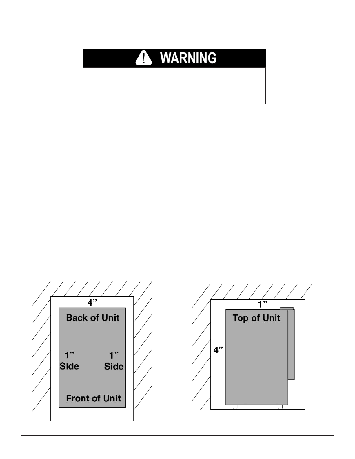
Location Requirements . . . . . . . . . . . . . . . . . . . . . . . . . . . . . . . . . . . . . . . . . . 7 - 8
lectrical Requirements . . . . . . . . . . . . . . . . . . . . . . . . . . . . . . . . . . . . . . . . . . . . 9
Function of Casters & Leveling Legs . . . . . . . . . . . . . . . . . . . . . . . . . . . . . . . . . 10
Reversing the Door Swing . . . . . . . . . . . . . . . . . . . . . . . . . . . . . . . . . . . . . . . . . 10
On-board Water Filter . . . . . . . . . . . . . . . . . . . . . . . . . . . . . . . . . . . . . . . . . . . . . 11
Water Supply . . . . . . . . . . . . . . . . . . . . . . . . . . . . . . . . . . . . . . . . . . . . . . . . . . . 12
Drain . . . . . . . . . . . . . . . . . . . . . . . . . . . . . . . . . . . . . . . . . . . . . . . . . . . . . . . . . . 12
Installation Types . . . . . . . . . . . . . . . . . . . . . . . . . . . . . . . . . . . . . . . . . . . . . . . . 13
OP RATION . . . . . . . . . . . . . . . . . . . . . . . . . . . . . . . . . . . . . . . . . . . . . . . . . . . . . 14 - 20
Final Checklist before Operation . . . . . . . . . . . . . . . . . . . . . . . . . . . . . . . . . . . . .14
Operating Method . . . . . . . . . . . . . . . . . . . . . . . . . . . . . . . . . . . . . . . . . . . . 14 - 15
How the Machine Makes Ice . . . . . . . . . . . . . . . . . . . . . . . . . . . . . . . . . . . . . . . .15
How the Machine Uses the Water . . . . . . . . . . . . . . . . . . . . . . . . . . . . . . . . . . . .15
Control Panel . . . . . . . . . . . . . . . . . . . . . . . . . . . . . . . . . . . . . . . . . . . . . . . . . . . 16
Working Procedures . . . . . . . . . . . . . . . . . . . . . . . . . . . . . . . . . . . . . . . . . . 17 - 18
Button Operation . . . . . . . . . . . . . . . . . . . . . . . . . . . . . . . . . . . . . . . . . . . . . . . . .19
Parameter Settings . . . . . . . . . . . . . . . . . . . . . . . . . . . . . . . . . . . . . . . . . . . . . . . 20
Normal Sounds . . . . . . . . . . . . . . . . . . . . . . . . . . . . . . . . . . . . . . . . . . . . . . . . . . 20
Preparing the Ice Machine for Long Storage . . . . . . . . . . . . . . . . . . . . . . . . . . . 20
CL ANING AND MAINT NANC . . . . . . . . . . . . . . . . . . . . . . . . . . . . . . . . . . . . . 21 - 24
xterior Cleaning . . . . . . . . . . . . . . . . . . . . . . . . . . . . . . . . . . . . . . . . . . . . . . . . 21
Interior Cleaning . . . . . . . . . . . . . . . . . . . . . . . . . . . . . . . . . . . . . . . . . . . . . . . . . 22
Condenser Cleaning . . . . . . . . . . . . . . . . . . . . . . . . . . . . . . . . . . . . . . . . . . . . . . 22
Water Distribution Tube Cleaning . . . . . . . . . . . . . . . . . . . . . . . . . . . . . . . . . . . . 23
Ice-Making System Cleaning . . . . . . . . . . . . . . . . . . . . . . . . . . . . . . . . . . . 23 – 24
MAJOR FUNCTIONS . . . . . . . . . . . . . . . . . . . . . . . . . . . . . . . . . . . . . . . . . . . . . . . . . . 24
RROR COD S . . . . . . . . . . . . . . . . . . . . . . . . . . . . . . . . . . . . . . . . . . . . . . . . . . . . . . 25
TROUBL SHOOTING . . . . . . . . . . . . . . . . . . . . . . . . . . . . . . . . . . . . . . . . . . . . . . 26 - 27
PARTS BR AKDOWN . . . . . . . . . . . . . . . . . . . . . . . . . . . . . . . . . . . . . . . . . . . . . . . . . .28
We reserve the right to make changes in specifications and design without prior notice.

2
ICE MACHINE SAFETY
Your safety and the safety of others is very important.
In this manual and on your appliance we have provided many important safety messages.
Always read and obey all safety messages.
SAVE THESE INSTRUCTIONS
This is the Safety Alert Symbol. This symbol alerts you to potential
hazards that can injure or kill you and others. All safety messages will
follow the Safety Alert Symbol and either the words "DANGER",
"WARNING" or "CAUTION".
DANGER means that failure to heed this safety
statement may result in severe personal injury or
death.
WARNING means that failure to heed this safety
statement may result in extensive product dam-
age, serious personal injury or death.
CAUTION means that failure to heed this safety
statement may result in minor or moderate per-
sonal injury, or property or equipment damage.
All safety messages alert you to the potential hazard, tell you how to reduce the chance of
injury, and let you know what can happen if the instructions are not followed.
IMPORTANT SAFETY INSTRUCTIONS
WARNING: To reduce the risk of fire, electric shock or injury
when using your ice machine, follow these basic precautions:
• Plug into grounded 3-prong outlet.
• Do not remove grounding prong.
• Do not use an adapter.
• Do not use an extension cord.
• Disconnect power before cleaning.
• Disconnect power before servicing.
• Replace all panels before operating.
• Use 2 or more people to move & install
ice machine

IMPORTANT SAFEGUARDS
● Plug into a grounded 3-prong outlet. Do not remove grounding prong, do not use
an adapter, and do not use an extension cord.
● It is recommended that a separate circuit, serving only your ice machine, be provided.
Use receptacles that cannot be turned off by a switch or pull chain.
● Do not connect or disconnect the electric plug when your hands are wet.
● Never unplug the ice machine by pulling on the power cord. Always grip the plug
firmly and pull straight out from the outlet.
● Never clean ice machine parts with flammable fluids. Do not store or use gasoline or
other flammable vapors and liquids in the vicinity of this or any other appliance. The
fumes can create a fire hazard or explosion.
● Before proceeding with cleaning and maintenance operations, make sure the power
line of the unit is disconnected and the water line is shut off. ( XC PTION: When
cleaning the machine’s ice making and water systems - See pages 21-24)
● Before operating, put all panels back into place.
● Never allow children to operate, play with or crawl inside the ice machine.
● Do not touch the evaporator by hand when the machine is operating.
● Unplug the ice machine or disconnect power before cleaning or servicing. Failure to
do so can result in electrical shock or death.
● Do not attempt to repair or replace any part of your ice machine unless it is specifi-
cally recommended in this manual. All other servicing should be referred to a qualified
technician.
Before the ice machine is used, it must be properly positioned and in-
stalled as described in this manual. Read the manual carefully. We
strongly recommend that you have a professional install your new ma-
chine. The warranty may be affected or voided by an incorrect installa-
tion. To reduce the risk of fire, electrical shock or injury when using the
ice machine, follow basic precautions, including the following:
3

4
● Use two or more people to move and install ice machine. Failure to do so can result
in back or other injury.
● Never install or operate the unit in an enclosed area, such as a closed cabinet. To en-
sure proper ventilation for your ice machine, the front of the unit must be completely
un obstructed. Choose a well-ventilated area with temperatures above 45ºF (7ºC) and
below 110º F (43ºC).
● The ice machine should not be located next to ovens, grills or other sources of high
heat.
● The ice machine must be installed with all electrical and water connections in accor-
dance with state and local codes. A standard electrical supply (115VAC, 60Hz, 15A),
properly grounded in accordance with the National lectrical Code and local code and
ordinances is required.
● Do not kink or pinch the power supply cord between the ice machine and cabinet.
● The fuse (or circuit breaker) size should be 15 amperes.
● It is important for the ice machine to be leveled in order to work properly. You may
need to make several adjustments to level.
● All installations must be in accordance with local plumbing code requirements.
● Make certain that the hoses are not pinched or kinked or damaged during installation.
● Check for leaks after connection.
● Although the unit has been tested at the factory, due to long-term transit and storage,
the first batch of cubes must be discarded.
● Remove the packing materials and clean the ice machine before using.
● Turn on the water supply tap before switching on the ice machine. Never turn the water
supply tap off when the ice machine is working.
● xcept to take ice from the unit, keep the door closed in order to reduce ice melting
and to promote proper ice formation.
● If the ice machine will not be used for a long time, before the next use, it must be thor-
oughly cleaned. Follow carefully the instructions provided for cleaning and use of sani-
tizing solution. Do not leave any solution inside the ice machine after cleaning.
● DO NOT touch the condenser fins. The condenser fins are sharp and can be easily
damaged.
● DO NOT use solvent-based cleaning agents or abrasives on the interior. These clean-
ers may transmit taste to the ice cubes, or damage or discolor the interior.
● Ice machine cleaner contains acids. DO NOT use or mix with any other solvent-based
cleaner products. Use rubber gloves to protect hand. Carefully read the material safety
instructions on the container of the ice machine cleaner.
● Do not use this apparatus for other than its intended purpose.

ELECTRICAL CONNECTION
Do not, under any circumstances, cut or remove the third (ground) prong from the power
cord. For personal safety, this appliance must be properly grounded. The power cord of
this appliance is equipped with a 3-prong grounding plug that mates with a standard 3-
prong grounding wall outlet to minimize the possibility of electric shock hazard from the
appliance. Have the wall outlet and circuit checked by a qualified electrician to make sure
the outlet is properly grounded. When a standard 2-prong wall outlet is encountered, it is
your responsibility and obligation to have it replaced with a properly grounded 3-prong
wall outlet. The ice machine should always be plugged into its own individual electrical
outlet which has a voltage rating that matches the rating label on the appliance. This pro-
vides the best performance and also prevents overloading house wiring circuits which
could cause a fire hazard from overheated wires. Never unplug your ice machine by
pulling on the power cord. Always grip the plug firmly and pull straight out from the outlet.
Repair or replace immediately all power cords that have become frayed or otherwise
damaged. Do not use a cord that shows cracks or abrasion damage along its length or
at either end. When moving the ice machine, be careful not to damage the power cord.
Extension Cord
Because of potential safety hazards under certain conditions, it is strongly recommended
that you do not use an extension cord with this ice machine.
TECHNICAL INFORMATION
Model: IM70
Electrical power: 115VAC ~ 60Hz
Power consumption: 13.2kWh/100 lbs of ice
Ice-making/Ice-harvest rated current: 3.0A/3.6A
Refrigerant: R134a, 3.17 oz.
High/Low Side Pressure: 350psig/130psig
Width × Depth × Height: 14.6″×24″×33.2″
Unit weight: 88 lbs
Ice-making capacity: 70 lbs/day*
Max. ice storage: 27 lbs
Ice shape: Cube
Ice cube dimensions: ¾″ × ¾″ × 1″
The technical data and performance index listed above should be used for reference
only. They are subject to change.
* The actual quantity of ice produced per day can vary with room and water conditions.
SAVE THESE INSTRUCTIONS
5

6
COMPONENT LOCATIONS
FRONTVIEW
REARVIEW
Power Cord 6’ Drain Hose
Control Panel
Water Distribution Tube
Water Inlet
Drain Outlet
Evaporator (Ice Mold)
Ice Full Swivel
Water Trough
Float Switch
Ice Storage Bin
ON/OFF Switch
6’ Fill Hose
Ice Scoop

ICE MACHINE INSTALLATION
Excessive Weight Hazard
Use two or more people to move and install ice machine.
Failure to do so can result in back or other injury.
Remove packaging materials
IMPORTANT: D n t rem ve any permanent instructi n labels r the data label n y ur ice machine.
Remove tape and glue from your ice machine before using.
● To remove any remaining tape or glue, rub the area briskly with your thumb. Tape or glue residue
can also be easily removed by rubbing a small amount of liquid dish soap over the adhesive with
your fingers. Wipe with warm water and dry.
● Do not use sharp instruments, rubbing alcohol, flammable fluids, or abrasive cleaners to remove tape
or glue. These products can damage the surface of your ice machine.
Cleaning before use
After removing all packaging materials, clean the inside of your ice machine before use. See "Interior
Cleaning" in the Cleaning and Maintenance secti n.
Installat on Clearances
View from TOP View from SIDE
7

8
Normal operating ambient temperature should be between 45º F (7º C) to 110º F
(43º C). Normal operating water temperature should be between 41º F (5º C)
and 90º F (32º C). Operation of the ice machine for extended periods outside of
these normal temperature ranges may affect production capacity.
● This ice machine should be installed by qualified personnel.
● To ensure proper ventilation for your ice machine, the front of the unit must be completely unob-
structed.
● When installing the ice machine under a counter, follow the recommended spacing dimensions
shown on the previous page. Allow 4" (102mm) or more clearance at rear, 1" (25.4mm) at the
top and sides for proper air circulation. The installation should allow the ice machine to be
pulled forward for servicing if necessary.
● Choose a well-ventilated area with temperatures above 45º F (7º C) and below 110º F (43º C).
● The unit should not be located next to ovens, grills or other sources of high heat.
● Installation of the ice machine requires a cold water supply inlet of 1/4” (6.35mm) soft copper
tubing with a shut-off valve.
● The ice machine requires a continuous water supply with a minimum pressure of 15 psig and a
static pressure not to exceed 80 psig. The temperature of the water feeding into the ice machine
should be between 41º F (5º C) and 90º F (32º C) for proper operation.
● Some water is very hard; softened water may result in white, mushy cubes that stick together. De-
ionized water is not recommended.
● The ice machine must be installed with all electrical and water connections in accordance with all
state and local codes.
● The unit should be located on a firm and level surface. It is important for the ice machine to be lev-
eled in order to work properly.
● A standard electrical supply (115V AC only, 60Hz, 15A), properly grounded in accordance with the
National lectrical Code and local codes and ordinances, is required.
● IMPORTANT: Do not kink or pinch the power supply cord between the ice machine and wall or cab-
inet.
Normal operating ambient temperature should be between 45º F (7º C) to 110º F (43º C). Normal oper-
ating water temperature should be between 41º F (5º C) and 90º F (32º C). Operation of the ice machine
for extended periods outside of these normal temperature ranges may affect production capacity

Electr cal Requ rements
Electrical Shock Hazard
Plug into a grounded 3- prong outlet.
Never remove the ground prong from the plug.
Never use an 3-prong adapter.
Never use an extension cord.
Failure to follow these instructions can result in fire, electrical
shock or death.
Before you move your ice machine into its final location, be sure you have the proper electrical con-
nection:
A standard electrical supply (115V AC only, 60Hz, 15A), properly grounded in accordance with the
National lectrical Code and local codes and ordinances, is required. The ice machine should always
be plugged into its own individual electrical outlet.
It is recommended that a separate circuit, serving only your ice machine, be provided. Use receptacles
that cannot be turned off by a switch or pull chain.
The fuse (or circuit breaker) size should be 15 amperes.
Recommended grounding method
For your personal safety, this appliance must be grounded. It is equipped with a power supply cord
having a 3-prong grounding plug. To minimize a possible shock hazard, the cord must be plugged
into a mating 3-pronged and grounding-type wall receptacle, grounded in accordance with the National
lectrical Code and local codes and ordinances. If a mating wall receptacle is not available, it is the
personal responsibility of the customer to have a properly grounded, 3-prong wall receptacle installed
by a qualified electrician.
9

Casters and Level ng Legs
The ice machine has been pre-installed with:
• Fixed casters at rear
• 360˚ casters in front
• Leveling legs in front.
The ice machine can easily moved by
rolling it to a desired location on the pre-
installed casters. The leveling legs must
be screwed clockwise until the front
casters touch the ground. When the de-
sired location is reached, screw the lev-
eling legs counter-clockwise lifting the
front casters off the ground.
Fixed Casters
at Rear
360˚ Casters
In Front
Leveling Legs
In Front
Revers ng the Door Sw ng
Proper operation of the unit requires that is level. To level the unit adjust the feet by turning
the required foot counter clockwise to increase the height and clockwise to reduce the height.
TOOLS NEEDED: Flat screwdriver, Phillips
screwdriver
IMPORTANT: Before you begin, unplug the ice
machine or disconnect power.
To remove door from h nges:
1. Remove the top hinge cover.
2. Using a Phillips screwdriver, remove the screws, and then remove top hinge. Keep the parts
together and set them aside.
3. Lift the door off of the bottom hinge. Set the door aside.
To replace door on h nges:
1. Using a flat screwdriver, remove the plug buttons from the screw holes opposite the door
hinges, top and bottom. Set aside.
2. Remove the bottom hinge and place it on the opposite side at the bottom of the door.
3. Position the door on the bottom hinge.
4. Align the door on the bottom hinge and replace the top hinge.
5. Replace top hinge cover.
6. Push the plug buttons into the original screw holes.
10

11
Onboard Water F lter
The ice machine requires the use of an internal water filter. The water filter is provided, but not in-
stalled. After installati n f a new filter, please discard the first tw ice harvests t insure that the filter
is purged f any impurities.
To install the water filter follow the steps outlined below.
1. Unplug the ice machine or disconnect power.
2. Loosen the two lower screws and remove the two upper screws on the front cover.
3. Gently remove the cover by lifting up and then out.
4. Place the filter with the filter tabs facing inward on the filter support.
5. Align the tabs, 2 left and 1 right, with the filter tab openings.
6. Gently push the filter forward into the receptacle so the tabs go into the tab openings.
7. Twist one quarter turn clockwise to lock the filter in place.
8. Make sure the filter is in place by gently pulling on it, it should not move.
9. Slide the front cover behind the two lower screws.
10. Replace the two upper screws and tighten the two lower screws on the front cover.
11. Plug the ice machine back in or reconnect power.
To remove the filter for replacement:
1. Unplug the ice machine or disconnect power.
2. Loosen the two lower screws and remove the two upper screws on the front cover.
3. Gently remove the cover by lifting up and then out.
4. Unlock the installed filter by turning the filter counter clockwise about one quarter of a turn. You
will feel the filter not turn any more.
5. Gently pull the filter out of the receptacle. After a filter has been attached to the receptacle for a
long time, it may need steady pressure to pull the filter off the receptacle. Slightly lifting the filter
off the filter support may also help.
FILTERINSTALLATION
1. Align Tabs (2-Left 1-Right)
2. Push Filter into Receptacle
3. Twist Clockwise to Lock
1
2
3
REPLACEMENTFILTER
# PAL5641P
Only Available
From

12
Dra n
You must connect the drain line before using the ice machine.
Follow the steps outlined below.
Connect ng the dra n l ne:
NOTE: If there is a drain line near the ice machine or it will
be used as an outdoor unit, the best choice is to drain water
to the drain line through the drain hose provided with the ice
machine.
1. Locate the floor drain near the ice machine. The distance
should be less than 6 feet since the drain hose provided with
the ice machine is about 6 feet long. Find the drain outlet on
the back of ice machine. Push the drain hose onto the drain
outlet and insert the other side of the hose into the drain line.
NOT : The drain hose should never be allowed to hang or loop
higher than the bottom of the ice storage bin.
2. All horizontal runs of drain lines must have a fall of 1/4” per foot. An air gap will likely be required be
tween the ice machine drain hose and the drain/waste receptacle. A stand pipe with a trap below it
would be desireable for the drain/waste receptacle. A floor drain is also acceptable.
3. If a floor drain or another drain is not available, a pump will be needed. We recommend PCP115.
4. Pour 1 gallon of water into the ice storage bin to check for leaks at all drain connections and at the
nut of the drain water hole. Tighten any connections or nuts that leak.
IMPORTANT: This ice machine is not a freezer. Infrequent drainage will cause
a high rate of melting in the ice storage bin.
Water Supply
The water supply should be ready at the point of installation. The water supply pressure should be a
minimum of 15 psig with a static pressure not more than 80 psig. (An outlet directly behind the ice ma-
chine will make installation easier.)
IMPORTANT:
• All installations must be in accordance with local plumbing code requirements. Professional installation
is recommended.
• Make certain that the hoses are not pinched or kinked or damaged during installation.
• Check for leaks after connection.
Water Inlet
Drain Outlet
Connect the water inlet to an appropriate water supply. Use of a
professional plumber is recommended.
Fill Hose
Drain Hose
PUMP
#PC115

Installat on Types
This ice machine has been designed for Mobile (free-standing), nclosed (as under a cabinet) or Built-
in (sealed) installation, indoor or outdoor. In any case, there must be adequate air space around the
unit for proper ventilation. (See diagrams on page 8 or below.)
Mobile installation:
A mobile installation will allow you to install the ice machine free-standing in any place you desire pro-
vided you have access to a water supply. You must follow the stated instructions for:
a. lectrical requirements
b. Water supply
c. Drainage
d. Leveling the ice machine
Enclosed Installation:
An enclosed installation will allow you to install the ice machine under a cabinet or inside a kitchen cab-
inet provided the required clearance space around the ice machine is respected. This installation has
the same requirements as a mobile installation.
Built-in Installation:
If this method of installation is chosen, it will still be necessary to allow adequate ventilation
space around the unit. The following additional items must be observed.
1. Place ice machine in front of installation location. Place the unit flat on the floor or on a platform de-
pending on your installation requirements.
2. The water supply line must be plumbed before connecting to the ice machine.
3. Connect the drain hose.
4. Turn on main water supply and tap. Check for water supply connection leaks. Tighten every connec-
tion (including connections at the water inlet).
5. If the electrical outlet for the ice machine is behind the cabinet, plug in the ice machine.
6. Push the ice machine into position.
7. Lower the front feet/stand-offs to level the ice machine.
8. Seal all around the cabinet to the floor with an approved caulking compound.
Installat on Clearances
View from TOP View from SIDE
13

14
OPERATION
F nal Check L st before Operat on
1. Have all packing materials and tape been removed from the interior and exterior of the ice machine?
2. Did you clean the ice storage bin? Initialize the cleaning proceedure, this proceedure will last 6 min.
and then enter into the icemaking proceedure.
3. Have the installation instructions been followed, including connecting the machine to water and
electricity?
4. Has the machine been leveled?
5. Is the ice maker in a site where the ambient temperature is between 45º (7ºC) and 110ºF (43ºC)
and the water temperature within 41ºF (5ºC) and 90ºF (32ºC) all year round?
6. Has the water supply pressure been checked to ensure a minimum of 15 psig with a static pressure
not to exceed 80 psig?
7. Is there a clearance of at least 4″ at the rear, and 1” at the top and sides for proper air circulation?
8. Has the power supply voltage been checked or tested against the nameplate rating? And has proper
grounding been installed for the ice machine?
9. Has the water filter been installed?
10. Is the ice machine plugged in?
11. Have you turned on the main water supply and the tap?
12. Have you checked for leaks at all water supply connections?
13. Is the drain properly installed?
Operat ng Method
1. Turn on the water tap. Set the Power switch on the front panel to the I/ON position and the Water
trough will fill. The ice machine will start working automatically.
2. After three minutes, the machine will automatically go into the ice-making stage, and the sound of
flowing water will be heard.
3. When the batch of ice has been fully formed , the ice will automatically be harvested to the ice stor-
age bin.
4. When the ice storage bin is full, the sheet of cubes does not fall completely and holds the ice-full flap
down. The machine stops making ice automatically.
5. The unit will start making ice again after the ice cubes are removed and the ice-full flap swings back
to operating position.
IMPORTANT:
• Although the unit has been tested and cleaned at the factory, due to long-term transit and storage,
the first batch of cubes must be discarded.
• Never turn the water supply tap off when the ice machine is working.
• Never touch the evaporator when the machine is running!
• xcept to take ice from the unit, keep the door closed to reduce ice melting and insure proper ice
formation.
Ice-
Making
Stage
Ice-
Harvesting
Stage
Ice-
Full
Stage

How the Mach ne Makes Ice
Turn the Power switch to the I/ON position. The Power indicator light will light and the machine will au-
tomatically go into the ice-making stage.
There are two distinct cycles: freeze and harvest.
During the freeze cycle, water flows to the evaporator surface. In the harvest cycle, the ice is released.
A complete cycle can take 15 to 40 minutes, depending on temperature and operating conditions.
Freeze: During the freeze cycle the compressor is pumping refrigerant, the fan motor is blowing air,
and the water pump is circulating water. When the batch of ice has been fully formed, the ice maker
stops the freeze cycle and begins the harvest cycle.
Harvest: During the harvest cycle the compressor is still operating, but the water pump has stopped.
The hot gas valve opens, diverting hot refrigerant gas into the evaporator. The hot refrigerant gas warms
the evaporator, causing the cubes to slide, as a unit, off the evaporator and into the storage bin. The
freeze cycle will restart when all the cubes have been harvested.
How the Mach ne Uses the Water
The ice machine begins with a fixed charge of water that is contained in the water trough. As the water
flows to the freezing evaporator surface, the portion of water that does not contain mineral impurities
will freeze and stick to the ice cube molds. The water containing impurities falls back into the water
trough. During the ice-making process, fresh water enters the water trough continuously as the water
from the trough freezes continuously on the evaporator.
vaporator
Water Inlet
Water Line
(Grey)
Refrigerant Line
(Clear)
Water Pump
Hot Gas Valve
Condenser
CompressorFan Motor
15

16
Buttons
Control Panel
LEDs
LED Light Switch
DISPLAY
LED/Button Name Color Function
ERROR error light red With error light on, SMG shows error code ( 01 to 11), check
error code list for details
FILTER filter light red When filter light is on filter has worked more than 180 days,
need to change the filter and reset dates.
ICE-FULL ice-full green When ice-full light is on the ice bin is full. After removing ice
cubes the machine will go back to ice making automatically
ICE- icemaking green When ice making light is on the ice machine is in ice making
MA ING light mode
HARVEST harvest green When harvest light is on the ice machine is in harvest mode
light
WATER water light green While water light is on inlet valve is open and water is flowing
into the water tank
POWER power light green When power light is on the ice machine is plugged in and main
power switch is on.
1 1K light green 1K and 2K lights used for counting of seconds of current pro-
cedure. 1K = 1000 seconds, 2K = 2000 seconds, 1K + 2K =
3000 seconds.
2 2K light green 2k = 2000 seconds.
MODE mode button Short press can change the ice machine working procedure be-
tween ice making and harvesting.
SET* set button Short press can change the set value
CLEAN clean button Short press can enter self-clean procedure
RESET reset button Press and hold reset button, then short press of ON/OFF. The
SMG will display “PPP”. The ice machine has been reset to de-
fault
ON/OFF on/off button Short press can turn on or turn off the ice machine
Note:
1. Short press means press the button more than 1 second, less than 3 seconds and then release.
Medium press means press the button more than 3 seconds, less than 10 seconds and then re-
lease. Long press means press the button more than 10 seconds and then release
2. SMG means the 3 digital LCD number display
3. Light on means the light is continually on. Light flash means the light is blinking.
4. Lights and buttons have more functions, see: Working Procedure, Button Operation & Parameter
Setting .

Work ng Procedures
Startup 888
All lights ON
for 1 second,
then OFF
Machine is plugged in, short press of ON/OFF (I/O)
button.
Machine program initialized.
Procedure SMG Indicator
Light
Starting Point/
Detail
Water
Fillup
COO->
Count
Seconds
Water Light
ON
Machine program initialized.
Water tank must be f lled before pump runs, other-
w se dry run damage w ll occur.
Clean CL
Ice-making &
harvest lights
flash,
water light on
if more water
is needed
System
pressure
balance
C10->
Count
Seconds
Ice-making
light on
Water tank clean.
Refrigerate systems reversing valve opens for 15 sec-
onds, compressor runs for 5 seconds, reversing valve
then closes, refrigerate system pressure is balanced.
Pre-Chill
C20->
Count
Seconds
Ice-making
light on
System pressure is balanced..
Compressor runs 30 seconds, condenser fan on,
water pump off, to pre-chill the evaporator, the proce-
dure lasts about 30 seconds.
Water tank is filled.
Clean water tank before making ice, startup-clean
procedure will last 6 minutes
Ice-Making
C30->
Count
Seconds
ice-making
light on
vaporator pre-chilled.
Compressor on, condenser fan on, water pump on,
the procedure lasts about 8-12 minutes, ends when
evaporator temperature drops below presets or time is
exceeded.
Ice-Making
Time Lapse
Continues
Count in
Seconds
Ice-making
light flashing
vaporator temperature is below presets.
Time lapse continues the ice making procedure for
thicker ice cubes, even if the preset temperature is
reached, default time lapse is 5 minutes.
Water
Discharge
C31->
Count
Seconds
Ice-making
light flashing
Ice-making time lapse finished.
The water discharge procedure is to prevent the water
tank from getting too cold and causing ice in the water
tank to jam the pump system. Default water discharge
time is 20 seconds
Harvest
C40->
Count
Seconds
Harvest light
on
Ice-making time lapse finished.
Reversing valve open & evaporator heated up, then
ice cubes are released. If ice cubes not released in 5
minutes, the pump turns on for 1 minute, watering the
ice cubes to help them release from the evaporator.
17

18
Work ng Procedures (continued)
Procedure SMG Indicator
Light
Starting Point/
Detail
Ice-Full
Checking
Continue
Count
Seconds
Harvest light
on
Ice cubes harvested from the evaporator.
If after the harvest procedure the swivel returns to its
initial position within 40 seconds, the system runs the
pre-chill procedure and starts a new ice making cycle.
Ice-Full
Status Ends FU0 Ice-full
light flashing
If during FU1 status the swivel returns to its initial po-
sition within 3 minutes the system will change to FU0
status, wait for 3 minutes then enter into new ice mak-
ing cycle, if swivel returns to its initial position after 3
minutes the system will directly enter into a new ice
making cycle.
Ice-Full
Status FU1 Ice-full
light on
Swivel has not returned to original position after ice-
full checking.
If after the harvest procedure the swivel does not re-
turn to its initial position within 40 seconds the system
pauses, SMG shows FU1 (ice-full)
Note:
1. Startup clean procedure will last 6 minutes, detail as below:
Pump runs 2 minutes -> water inlet and discharge for 1 minute -> pump runs 2 minutes -> water
inlet and discharge for 1 minute.
2. During ice making cycle, if short press the clean button will enter standard clean procedure (30
minutes), detail as below:
Pump runs 12 minutes -> water inlet and discharge 3 minutes -> pump runs 12 minutes -> water
inlet and discharge 3 minutes.
3. Startup clean procedure is available while the machine is set to CL1.
4. Water discharge procedure is not available while the machine is set to P00.

Button Operat on
1. Main power off, means you unplug the ice machine or turn the main power switch off.
2. SMG off, means the ice machine is plugged in and main power switch is on, but SMG shows OFF.
1. Short press means press the button more than 1 second, less than 3 seconds then release.
2. Medium press means press the button more than 3 seconds, less than 10 seconds, then release
3. Long press means press the button more than 10 seconds then release
Status Operation Light &SMG Details
Main
Power
Off
Turn on the main
power switch at front
lower right side of
ice machine
Power light:ON
SMG:OFF
Main switch controls the general
power of the whole ice machine.
Please turn it off if the ice machine
will not be used for a long time.
SMG
OFF
Press and hold the
R S T button,
before release,
short press ON/OFF
button
SMG: shows 888 for
1 second, then PPP
for 3 seconds
all other lights: on for
1 second and then off
This operation is to reset all the
settings to “factory default".
All other
status
except
SMG
showing
OFF
SMG: CL
Ice Making Light
Flashing
Harvest Lights
Flashing
This operation will force the ice
machine to enter into a clean
cycle, this cycle is 30 minutes.
Short press clean or mode button,
can terminate the clean process,
and enter into new ice making
cycle.
SMG
OFF
Long press
S T button
SMG: shows number
between 001 and 180
Filter Light: Flashing
The number shows the days since
the filter was installed. If the
number is larger than 180 days,
the filter light will stay on, change
the filter. After the filter has been
changed, medium press the reset
button to reset the days to zero.
SMG
OFF
Short press
ON/OFF button
SMG: shows 888 for
1 second, then shows
COO
all other lights: on for
1 second and then off
This operation is to turn on the ice
making process.
Short press CL AN
button
19
Other manuals for IM70
1
Table of contents
Other Parts Connect Ice Maker manuals