Plunger Cart Usage
2
012-14781A
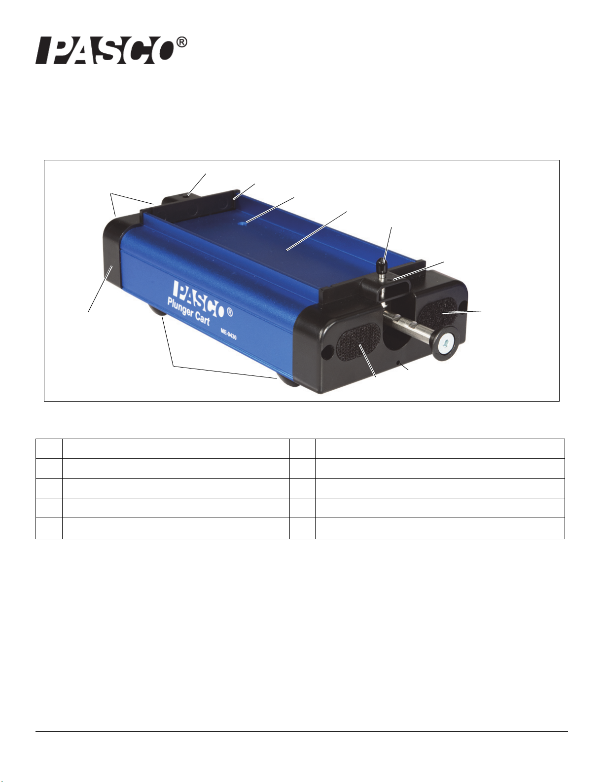
that can hold extra masses. The tray has threaded holes
for attaching PASCO accessories such as a Cart Adapter
that can be used to mount a Motion Sensor, and slots for
holding a Cart Picket Fence.
Other Features
The Plunger Cart has ball-bearing wheels that are
designed with narrow edges to minimize friction. The cart
has a spring suspension system that prevents damage to
the wheels and internal components if the cart is dropped
or stepped on. Plunger Carts can be stacked for easy stor-
age.
Plunger Operation
The plunger has three indentations on the top side that you
can see when the plunger is fully extended. Inside the cart
is a Retention Bar located above the plunger. When the
plunger is pushed in far enough so that an indentation lines
up with the Retention Bar, the plunger will be held in that
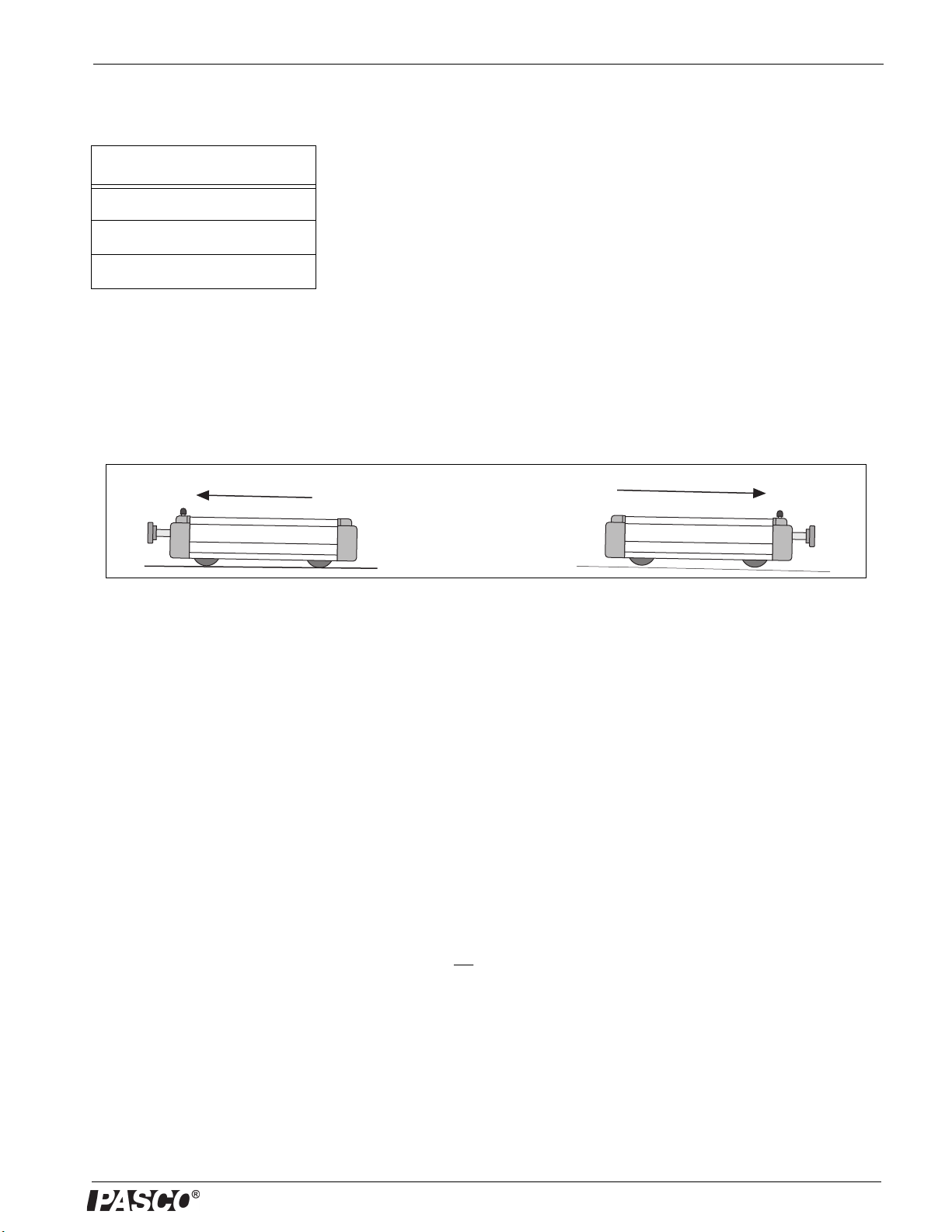
position until the Plunger Trigger is pushed down. If the end
of the plunger is next to an object such as a heavy book,
the Plunger Cart will accelerate away from the object when
the Plunger Trigger is pushed down and the plunger
applies a force.
Positions #1 and #2
Apply a slight upward force on the end of the plunger, Push
the plunger into the Plunger Cart until you hear or feel the
first “click” (Position #1) as the indentation on the plunger
lines up with the Retention Bar. Lower the end of the
plunger slightly to disengage it from the Retention Bar, and
push the plunger a little farther into the Plunger Cart.
Slightly raise the end of the plunger and push the plunger
until you hear or feel the second “click” (Position #2). To
release the plunger, push down on the Plunger Trigger.
CAUTION: The plunger comes out rapidly, so be prepared.
For example, do not hold the plunger end of the Plunger
Cart against your eye (or anything else that would be
harmed) if the plunger is released.
Position #3
Apply a slight upward force on the end of the plunger. Push
the plunger all the way into the Plunger Cart until the Posi-
tion #3 indentation catches on the Retention Bar. The end
of the plunger will be flush with the end cap of the Plunger
Cart. The plunger pushes outward with maximum force
when it is released from Position #3. This is also the posi-
tion used when doing inelastic collisions with the Velcro
bumpers.
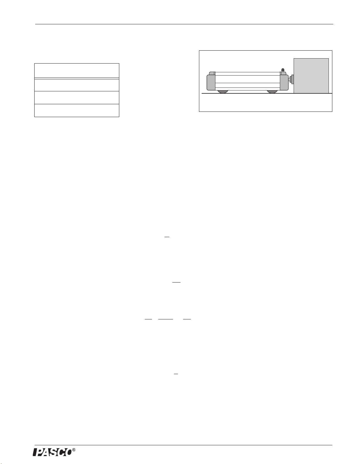
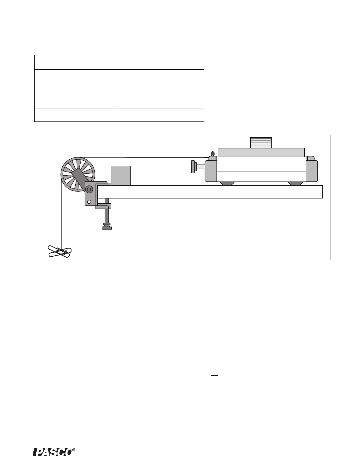
Usage
The following illustrations show a few of the ways that the
Plunger Cart is used. See the PASCO web site at
www.pasco.com for more information.
Collision Cart
The PASCO ME-9454 Collision Cart is a “twin” of the
Plunger Cart but it is red and does not have a spring
plunger. The different colors make it easier to keep track of
the carts in collisions studies.
Plunger Cart Dynamics Systems
Plunger Carts are included in bundles with tracks, adjust-
able feet, end stops, a track pivot clamp a friction block,
and other accessories such as mass bars, springs, photo-
gate brackets, “cart picket fences”, and a pulley with clamp.
.
Plunger Trigger
Approximate Position of
Plunger Retention Bar
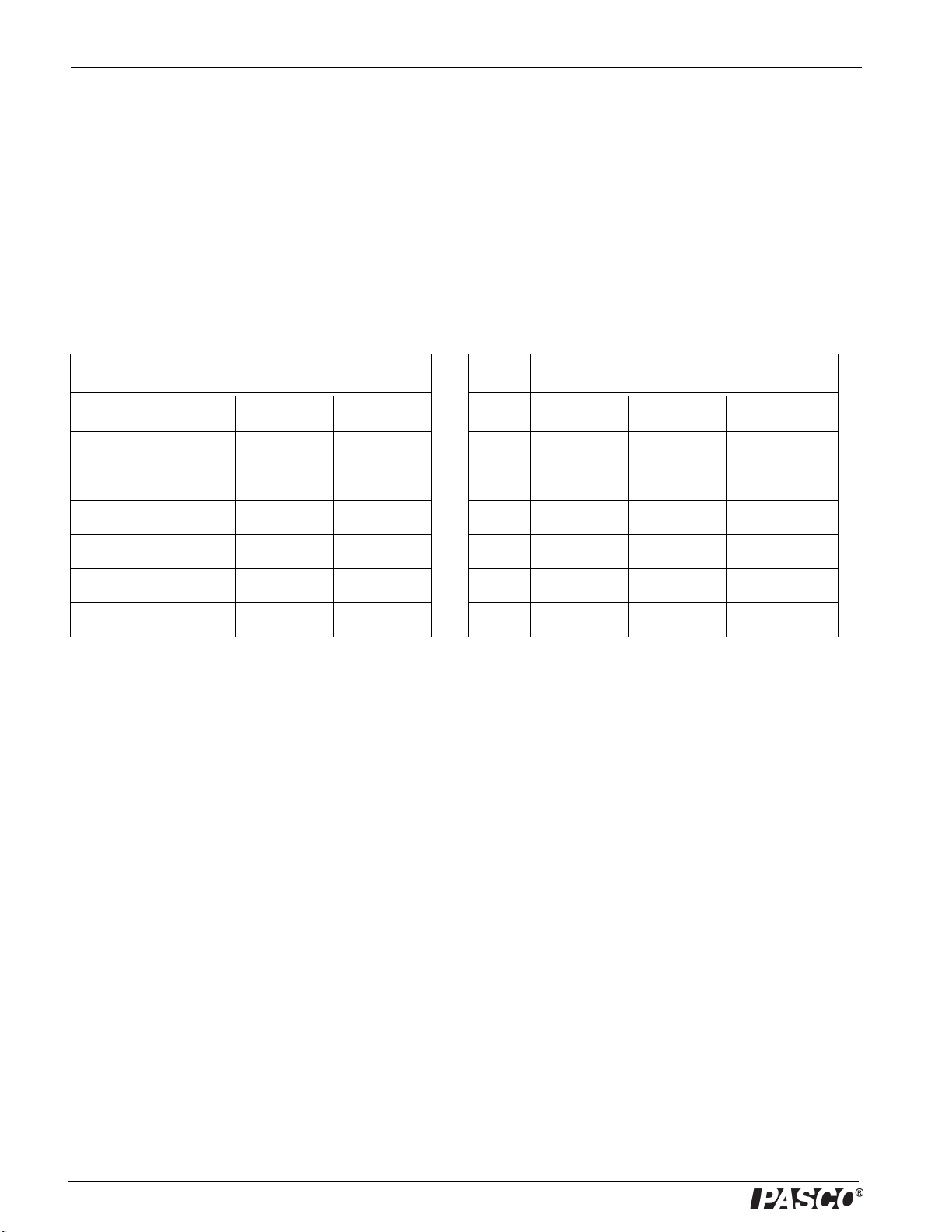
Position #1
Position #2
Position #3