PASCO PI-9877 User manual

!
DC Power Supply
PI-9877
Instruction Manual
012-09125A

DC Power Supply Table of Contents
Contents
Introduction . . . . . . . . . . . . . . . . . . . . . . . . . . . . . . . . . . . . . . . . . . . . . . . . . . . . . . . . . . . 3
Typical Uses . . . . . . . . . . . . . . . . . . . . . . . . . . . . . . . . . . . . . . . . . . . . . . . . . . . . . . . . . .4
Specifications. . . . . . . . . . . . . . . . . . . . . . . . . . . . . . . . . . . . . . . . . . . . . . . . . . . . . . . . . . 4
Tutorial. . . . . . . . . . . . . . . . . . . . . . . . . . . . . . . . . . . . . . . . . . . . . . . . . . . . . . . . . . . . . . . 7
Basic Operation . . . . . . . . . . . . . . . . . . . . . . . . . . . . . . . . . . . . . . . . . . . . . . . . . . . . . . . 19
Standard Functions (Rectangle, Ramp, and Stair) . . . . . . . . . . . . . . . . . . . . . . . . . . . . 22
Custom Program . . . . . . . . . . . . . . . . . . . . . . . . . . . . . . . . . . . . . . . . . . . . . . . . . . . . . . 28
Technical Support . . . . . . . . . . . . . . . . . . . . . . . . . . . . . . . . . . . . . . . . . . . . . . . . . . . . . 35

DC Power Supply
PI-9877
!3
Introduction
The PI-9877 DC Power Supply sources 0–18 volts at up to 1 amp. You can use the Power Supply as a simple
constant-voltage source, or take advantage of its advanced features to output periodic functions and custom pro-
grams.
Included Equipment Part Number
DC Power Supply PI-9877
AC Power Adapter 540-062

!
DC Power Supply Typical Uses
4
Typical Uses
The Power Supply works well with a variety of electronic circuits, motors, lamps,
heaters, and Peltier devices, including the PASCO apparatus listed below.
Specifications
Model Number Name Comments
ET-8499 Calorimeter Set the Power Supply’s Stair function for a single heat pulse (see
page 26).
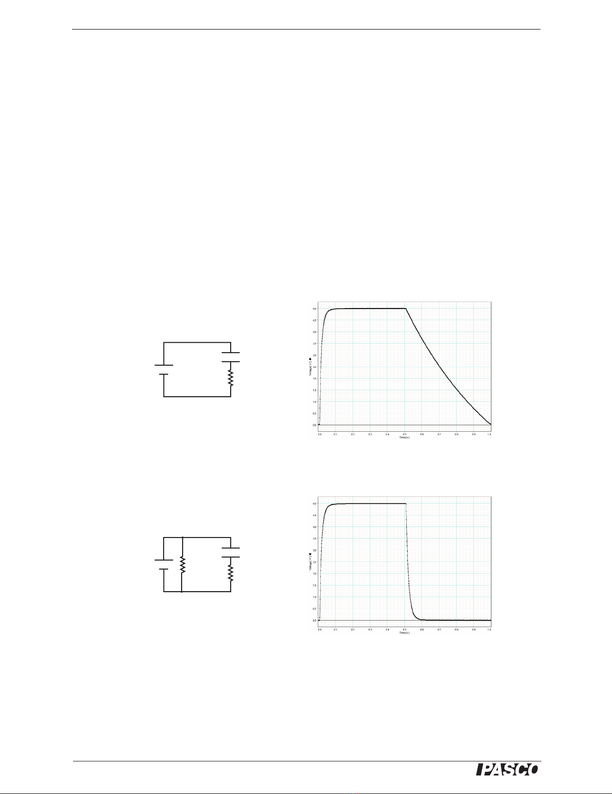
EM-8678 Charge/Discharge Circuit Use the Power Supply to charge the circuit’s capacitor or battery. Set the
Power Supply’s maximum voltage to 5 V (see page 20).
ET-8782 Thermoelectric Circuit Set the Power Supply’s maximum voltage to 10 V (see page 20).
ME-8088 Centripetal Force
Apparatus
Use the Power Supply’s ramp function (see page 23) to slowly increase
the rotational speed.
ME-8750 Mechanical Oscillator
Driver
Drive dynamics carts (such as ME-6950) or the Chaos/Driven Harmonic
Accessory (CI-6689A).
ME-8955 Rotational Motor Drive Drive the Rotating Platform (ME-8951) with the Magnetic Levitation
Accessory (EM-8947) or Rotational Acceleration Tank (ME-8957).
TD-8513 Heat Conduction Apparatus Power the apparatus with a positive-offset rectangle wave (see page 22)
or sine wave (the Power Supply’s default custom program, see page 28).
General Specifications
Output Voltage Adjustment 0–18 V
Volt ag e A dju st Res o lut i on 10 mV
Volt ag e A dju s t Accu racy 0.25% of setting or 20 mV, whichever is larger
Current-limit Shutdown Programmable, 0.010–1.050 A
Current Measurement Accuracy 2%
Load Regulation 0.5%
Output Noise 10 mV peak-to-peak typical, 60 mV peak-to-peak at full load
Function-specific Specifications
Function 1: Constant DC Output
(see page 19)
Monitor voltage or current, or cycle with adjustable time
Function 2: Rectangle Wave
(see page 22)
Programmable maximum voltage
Programmable minimum voltage
Programmable period: 0.1–999 s
Programmable duty cycle: 1–99%, Jitter: ±300 µs
Monitor voltage or current
Function 3: Ramp
(see page 23)
Programmable maximum voltage
Programmable minimum voltage
Programmable period: 0.1–999 s
Programmable ramp direction (ascending or descending)
Alternating ramp direction option (triangle wave)
Programmable number of cycles: 1 to 999, or infinite
Monitor voltage or current

!
Model No. PI-9877 Specifications
5
Combining Two Units Two or more Power Supplies can be connected in series.
Connect the negative terminal of one unit to the positive terminal of the other.
Excessive voltage levels can be achieved when combining units in this way; students
should do so only under the supervision of a qualified instructor.
Storage For easy storage of multiple units, indentations in the Power Supply
accept the feet of an identical unit stacked on top of it.
Function 4: Stair
(see page 25)
Programmable maximum voltage
Programmable step voltage: 0.01–18.00 V
Programmable minimum voltage
Programmable step time: 0.1–999 s
Programmable stair direction (ascending or descending)
Alternating stair direction option
Programmable number of cycles: 1 to 999, or infinite
Monitor voltage or current
Function 5: SET MAX
(see page 20)
Programmable voltage limit: 0.01–18.00 V
Programmable maximum current: 0.010–1.050 A
Automatic shutdown timer: 0.01–99.99 hours
“Hidden” Global Maximum voltage: 0.01–18.00 V (remembered after power off)
Function 6: PROGRAM
Custom program entry
(see page 28)
3–99 programmable voltage points (remembered after power off)
Edit modes: append, insert, delete point, delete entire program
Function 7: PLAY
Custom program output
(see page 29)
Programmable scale factor: 1–100% of programmed voltage
Programmable step-time: 0.1–999 s
Step-style and vector-style options
Programmable play direction (forward or backward)
Alternating play direction option
Programmable number of cycles: 1 to 999, or infinite
Monitor voltage or current

!
DC Power Supply Specifications
6
Experiment-design Considerations Please note the following properties of
the Power Supply when planning an application:
•ThePowerSupplyisover-currentprotected,butitisnotcurrent-limitedor
current-regulated. If the maximum output current (1 amp by default, or lower if
you have changed the maximum-current setting) is exceeded, the Power Supply
will need to be manually reset before operation can resume. See “Over-current”
on page 20.
•Theoutputvoltagerangeis0to18V.Toachieveanegativevoltageswitchthe
positive and negative leads.
•Thisdeviceisaprogrammablepowersource,notafunctiongenerator.Themax-
imum frequency of the rectangle and ramp functions is 10 Hz. The maximum fre-
quency of the default sine-wave custom program is about 0.1 Hz.
•ThePowerSupplyisdesignedforcurrentflowinonedirection:outoftheposi-
tive terminal and into the negative terminal. In the example illustrated below, the
Power Supply is switched from 0 V to 5 V, t h e n b a c k t o 0 V. T h e c a p a c i t o r d o e s
not discharge in a predictable way because there is not a simple path to ground.
To provide a path to ground, connect a resistor across the Power Supply’s
terminals as shown.
A current-sinking resistor is not typically required when driving motors, lamps
and heating resistors since these devices have a low DC resistance.
"#$%&
'())*+
!
"
,--.#/
,--.$
,--.#/
,--.$
"#$%&
'())*+
!
"
0-.$

!7
Tutorial
This tutorial will introduce you to the DC Power Supply. As you follow the steps, it will be helpful to
measure and view the Power Supply’s voltage output. Here are three possible ways to do that:
1. Use a data-acquisition program such as DataStudio with a voltage sensor. The sample waveforms
shown in the tutorial were collected in this manner.
2. Use an digital storage oscilloscope capable of displaying several second’s worth of data.
3. Use a normal volt meter. This option will not allow you to reproduce the graphs on the following
pages, but you will be able to observe the variation of the Power Supply’s output.
If possible, connect a load resistor (or other device such as a small light bulb) to the output so that you
can look at the current draw. You can use any resistor from about 20 Ωto 100 Ω, but check the power
rating to make sure it will not overheat; during the tutorial, you will apply voltages up to 10 volts.
Set-up
POWER and OUTPUT connections
1. Plug the AC adapter into a wall outlet and
into the port labeled POWER on the Power
Supply.
2. Use a pair of banana-plug patch cords to
connect a load resistor (or other device) to
the Power Supply’s red (+) and black (−)
OUTPUT ports.
3. Connect a voltage sensor, meter, or oscillo-
scope to the OUTPUT ports.
Buttons
4. Notice the two buttons: and . You will
use these buttons, along with the knobs, to
control the Power Supply’s output and dis-
play.
Load factory settings
5. Push and hold both buttons. While holding
the buttons, turn on the power switch (if it is
already on, turn it off and on again). Con-
tinue to hold both buttons until the display
shows LLLL, then release the buttons. The
original factory settings have been loaded.

!
DC Power Supply
8
Tutorial
Function 1: DC Voltage
The Function knob
1. Turn the Function knob to the Constant DC
position ( ). The display briefly shows F1
(for “Function 1”), then 0.00 (for zero volts).
The Voltage LED is lit, indicating that the
quantity displayed is voltage in units of
volts.
Set voltage
2. Turn the Coarse knob to set the voltage to
4.00 V. Note that the displayed voltage
reflects the actual voltage at the output ter-
minals.
Turn the Fine knob. If you rotate it slowly,
the voltage changes by 0.01 V per detent. If
you rotate the knob more quickly, it changes
by 0.04 V per detent. Adjust the voltage back
to 4.00 V.
Temporarily switch off output
3. Quickly press and release to temporarily
switch off the output. The Voltage LED
blinks rapidly, and the actual output voltage
drops to zero, though the display still shows
the voltage setting.
Turn the Coarse knob. Note that you can
adjust the voltage setting while the actual
output remains zero. Return the voltage set-
ting to 4.00 V
Press to switch the output back on. The
Vo l t a g e L E D i s n o w o n s t e a d i l y t o i n d i c a t e
that the output voltage is live.
!"#
$%&
'(%)
'*+,*%$
-./0#1+/
1#234524
61
7%84529*%
:5;%
75<) '45=&
'%4.>5?=<(<
@5*(%3
A24%&
#&.AB=4
1(34#<
"	&5<
"*5+
1(34#<
"	&5<

!
Model No. PI-9877
9
Tutorial
Change display
4. Quickly press and release . The Current
LED lights, and the display now shows out-
put current in amps. Press a few times to
toggle the display between current and volt-
age.
While viewing current on the display, turn
the Coarse and Fine knobs. You are actually
adjusting the voltage, but you see the result-
ing current change on the display.
Set display-toggle time
5. Press and hold untiltheTimeLEDstarts
blinking, and the display shows 0; while
holding the button, turn the Coarse knob to
change the display to 2. Release the button.
The display now automatically toggles
between current and voltage every 2 sec-
onds.
Press to pause the display toggling; press
again to resume.
Reset output and display
6. Press and hold until the display shows
0.00. Release the button. You have just reset
the output voltage to zero and the display to
voltage.
For more information about constant DC output, see
page 19.
Function 5: SET MAX
Set maximum voltage
1. Turn the Function knob to SET MAX. The
display briefly shows F5 (for “Function 5”)
followed by 18.00, which is the Power Sup-
ply’s voltage-limit setting. (Note that the
actual output voltage is zero.)
Turn the Coarse knob to set the voltage limit
to 10 V.
Turn the Function knob back to Constant DC
mode ( ). Try to adjust the output voltage
to over 10 volts.
2. Turn the Function knob back to SET MAX.
Press once to display the maximum-
current setting. Turn the Coarse and Fine
knobs to adjust the maximum current to
0.210 A.

!
DC Power Supply
10
Tutorial
Display shows current Over Load
Turn the Function knob back to Constant DC
().IncreasethevoltageuntiltheCurrent
LED blinks amber and the display shows
OL (for “overload”) to indicate that the max-
imum current has been exceeded and the out-
put has automatically turned off (this will
happen only if you have a load hooked to the
power supply). Press to return the Power
Supply to normal operation.
Turn the Function knob back to SET MAX.
Press once to display the maximum cur-
rent setting. Adjust it back to 1.05 A.
Set countdown time in hours
3. Press so that the Time LED starts blink-
ing and the display shows 0.00; this is the
countdown time in hours. Turn the Fine
knob to set the time for 0.01 hour (36 sec-
onds). Note that the Time LED is blinking to
indicate that the countdown has not started
yet.
Display shows auto off
Press to start the countdown. The Time
LED is now lit steadily. Turn the Function
knob back to Constant DC ( ) and set the
voltage to 1 V. Wait for the remainder of the
36 seconds. When the countdown time has
elapsed, the display shows OFF to indicate
that the output has been switched off. Press
to return the Power Supply to normal
operation.
Setting “Hidden” Global Maximum voltage
4. Turn the Function knob back to SET MAX.
Push and hold both buttons until the Voltage
LED starts blinking fast and the display
shows 18.00 (this is the Global Maximum
voltage setting); while holding both buttons,
turn the Coarse knob to change the Global
Maximum to 14.00 V. Release both buttons.
You ha ve ju st set t he Po wer S upply s o that
the output voltage, the voltage-limit setting,
and any other voltage setting cannot exceed
14 V.
5. Repeat the previous step to turn the Global
Maximum back to 18 V.
For more information about setting maximum values,
see page 20.

!
Model No. PI-9877
11
Tutorial
Function #2: Rectangle Wave
Rectangle Wave
1. Turn the Function knob to Rectangle Wave
().ThedisplaybrieflyshowsF2, then
0.00 (the rectangle wave’s maximum-voltage
setting).
2. Turn the Coarse knob to set the maximum
voltage to 6.00 V. Note that the actual output
voltage is zero (the Voltage LED blinks to
indicate that the displayed voltage is not
live).
3. Press to start running the function: a 6 V
positive square wave with a 2 s period.
(Note the START label printed above the
button, which indicates what happens when
you press the button.)
4. Try turning the Coarse and Fine knobs; the
knobs have no effect when the function is
running.
5. Press and hold forabout1secondtostop
running the function.
(Note the STOP label printed below the but-
ton, which indicates what happens when you
press and hold the button.)
Minimum voltage set to 2 V
6. Press and hold (SET);theVoltageLED
starts blinking fast and the display shows the
minimum-voltage setting; while holding the
button, turn the Coarse knob to adjust the
minimum voltage to 2.00 V. Release the but-
ton.
Press (START). The output voltage now
alternates between 6 V and 2 V.
Press and hold (STOP).

!
DC Power Supply
12
Tutorial
Period set to 3 s
7. Press . The Time LED lights and the dis-
play shows the rectangle wave’s period (in
seconds). Turn the Coarse and Fine knobs to
change the period to 0.13 s. (By turning the
Fine knob slowly you can adjust the period
in 0.01 s increments.)
Turn the Coarse and Fine knobs to set the
period to 3.00 s.
Press (START). The output voltage now
completes a full cycle every 3 seconds.
Press and hold (STOP).Notethatthedis-
play has gone back to showing the maxi-
mum-voltage setting.
Duty cycle of 10%
8. Press (DISPLAY) so that the Time LED
is lit.
Press and hold (SET); the Time LED
starts blinking and the display shows 50 (for
a duty cycle of 50%); while holding the but-
ton, turn the Coarse knob to change the duty
cycle to 10%.
Press (START). The output voltage now
spends 10% of the time at the maximum
voltage and 90% of the time at the minimum
voltage.
Press and hold (STOP).
For more information about the Rectangle Wave func-
tion, see page 22.
Function 3: Ramp
Ramp with 2 V minimum and 8 V maximum
1. Turn the function knob to Ramp ( ). The
display briefly shows F3, then 18.00 (the
ramp’s maximum-voltage setting).
2. Set the maximum voltage to 8.00 V.
3. Press and hold (SET); the Voltage LED
starts blinking fast and the display shows the
minimum-voltage setting; while holding the
button, adjust the minimum voltage to
2.00 V.
4. Press (DISPLAY); the Time LED lights
and the display shows the ramp’s period. Set
the period to 2.00 s.
5. Press (START) to run the function and
observe the waveform.
Press and hold (STOP).

!
Model No. PI-9877
13
Tutorial
A negative period setting causes a descending ramp
6. Press (DISPLAY) to display the period.
Turn the Coarse knob to set the period to
–2.00 s (a negative value).
Press (START) to run the function and
observe the waveform. Note that the nega-
tive period setting makes the ramp descend.
Press and hold (STOP).
Press (DISPLAY) to display the period
again and set it back to +2.00 s.
Ramp plays twice and then stops
7. Press and hold (SET); the Time LED
starts blinking fast and the display shows 0
(the “auto-repeat” setting); while holding the
button, turn the Fine knob to change the
auto-repeat setting to 2.
Press (START) to run the function. The
output now completes two ramps and stops
automatically.
A negative auto-repeat setting causes a triangle wave
8. Press (DISPLAY) so that the Time LED
is lit. Press and hold (SET) and adjust the
auto-repeat setting to –2 (a negative value).
Press (START) to run the function and
observe the waveform. The ramp now alter-
nates between ascending and descending to
form a triangle wave. It completes two full
cycles and stops automatically.
For more information about the Ramp function, see
page 23.

!
DC Power Supply
14
Tutorial
Function 4: Stair
Stair
1. Turn the Function knob to SET MAX. Set
the Power Supply’s voltage limit to 8 V.
2. Turn the Function knob to Stair ( ). The
display briefly shows F4, then 1.00 (the
voltage-step setting).
3. Press and hold (SET); the Voltage LED
starts blinking fast and the display shows the
minimum-voltage setting; while holding the
button, adjust the minimum voltage to
1.00 V.
4. Press (DISPLAY) so that the Time LED
is lit and the display shows the step-time set-
ting. Set the step time to 1.00 s.
5. Press (START) to run the function and
observe the waveform. Note that the top of
the stair is determined by the Power Supply’s
voltage-limit setting.
Press and hold (STOP).
Stair with a negative auto-repeat setting
6. Press (DISPLAY) so that the Time LED
is lit again. Press and hold (SET); the
Time LED starts blinking and the display
shows the auto-repeat setting; while holding
the button, adjust the auto-repeat setting to
–0 (“negative zero”).
Press (START) to run the function and
observe the waveform. The stair now alter-
nates between ascending and descending.
Press and hold (STOP).
7. Turn the Function knob to SET MAX. Turn
the Coarse knob to set the voltage limit to
18 V.
For more information about the Stair function, see
page 25.

!
Model No. PI-9877
15
Tutorial
Function 7: PLAY (Custom Program)
Playing stored custom program
1. Turn the Function knob to PLAY. The dis-
play briefly shows F7, then 100 (for a scale-
factor setting of 100%).
2. Press (START) to start playing the
default custom program.
After the program has played for several sec-
onds, press and hold (STOP).
If you are using a voltage sensor, be sure to stop the
program before it exceeds 10 V.
Scale Factor of 50%
3. Turn the Coarse knob to change the Scale
Factor to 50%.
Press (START) to play the program
again; each voltage point is now half of what
it was before. Press and hold (STOP).
Graph type set to 0
4. Press and hold (SET); the display shows
1, the graph-type setting; while holding the
button, turn the Coarse knob to change the
graph type setting to 0.
Press (START) to play the function; the
voltage ramps smoothly through the program
rather than jumping from one level to the
next.
Press and hold (STOP).

!
DC Power Supply
16
Tutorial
Entire program
5. Press (DISPLAY); the Time LED lights
and the display shows the step time (or time
interval between points) in seconds. Set the
step time to 0.10 s.
Press (START) to play the program; let
the entire program run and stop automati-
cally. Since there are 51 points stored in the
program, the total run time is 5.1 s.
Program alternating between playing forward and back-
ward to form a sine wave
6. Press (DISPLAY) to light up the Time
LED again. Press and hold (SET);the
Time LED starts blinking fast and the dis-
play shows the auto-repeat setting; while
holding the button, set auto-repeat to –0
(“negative zero”).
Press (START) to play the program
again. The program now alternates between
playing forward and backward resulting in a
positive-offset sine wave.
Press and hold (STOP).
Program stops before exceeding the voltage limit
7. Turn the Function knob to SET MAX, and
set the voltage limit to 5 V. Turn the Function
knob back to PLAY.
Press (START) to play the program. The
output will not exceed the voltage limit: just
before the program reaches 5 V, it stops, the
output voltage drops to zero, and the voltage
LED flashes amber. Press and hold to
restore normal operation.
8. Turn the Function knob to SET MAX, and
set the voltage limit back to 18 V.
For more information about playing custom programs,
see page 29.
Function 6: PROGRAM
1. Turn the Function knob to PROGRAM. The
display briefly shows F6, then P51to indi-
cate the number of points stored in memory.

!
Model No. PI-9877
17
Tutorial
Stored point #10
2. Turn the Coarse knob one detent counter-
clockwise to view one of the stored points.
Turn the Coarse knob some more (a few
rotations) until you see Point #10; the dis-
play shows P 10, then (after you stop turning
the knob) it shows 1.40, the stored voltage of
Point #10.
3. In this step you will delete Point #10, then
insert a new point in its place with a value of
2.00 V.
Press and hold todeletePoint#10(think
of it as a backspace button). Release the but-
ton after you see the display flash ––––.
The display now shows 1.72, the value of
what had been Point #11, but is now (tempo-
rarily) Point #10. (As shown in the third col-
umn of the table, right.)
Press . The display starts flashing, which
is your prompt to set a new voltage. Turn the
Coarse and Fine knobs to set the voltage to
2.00 V; then press to store that value.
4. Press and hold (STOP) to exit edit mode.
The display shows P51to indicate the num-
ber of stored points.
Erase the stored program
5. Press and hold both buttons simultaneously
until the display shows EEEE (for
“Erased”); release the buttons. You have just
erased the stored program. The display now
shows P0because there are zero stored
points.
6. To enter a new program, press . The dis-
play starts flashing.
Turn the Coarse and Fine knobs to select a
voltage for the first point; then press to
store it. Turns the knobs to select a voltage
for the next point and press to store it.
Store several more points. (A program must
have at least three points.)
When you are finished, press and hold
(STOP).
7. Turn the Function knob to PLAY and press
(START) to play your new program.
For more information about entering and editing a cus-
tom program, see page 28.
Point
Number
Original
Program
After
Deleting
Point #10
After
inserting a
New Point
80.850.850.085
91.111.111.11
10 1.40 1.72 2.00
11 1.72 2.06 1.72
12 2.06 2.44 2.06

!
DC Power Supply
18
Tutorial

!
Model No. PI-9877 Basic Operation
19
Basic Operation
Connections
Connect the included AC Power Adapter to the POWER
port of the Power Supply and to a power outlet
(120–240 VAC, 50–60 Hz). Slide the power switch to
the ON position; when the unit if first turned on, the out-
put voltage is zero.
Use two 4 mm banana-plug patch cords to connect the
OUTPUT ports of the Power Supply to a device such as
a motor, light bulb, or experimental apparatus.
Display, Knob, and Button Overview
The Power Supply indicates its output voltage, output
current, and settings on the digital display. The type of
data shown on the display is indicated by the Voltage,
Current, and Time LEDs. The Voltage or Current LED
lights steadily when the digital display is showing the
actual output voltage or current. If the Current or Volt-
age LED is blinking, then the actual output voltage is
zero.
The Power Supply is controlled through the Function
knob, the Coarse and Fine adjustment knobs, and two
push buttons.
The Function knob is a rotary switch with seven posi-
tions. Each position represents a different output func-
tion or mode of operation. For simple DC output, set the
knob to .
The Coarse and Fine knobs adjust the output voltage or
the setting shown on the digital display. Rotate the
Coarse knob to adjust the quantity in large steps; rotate
the Fine knob to adjust it in small steps. The Fine knob
is speed-sensitive: rotating it quickly causes a larger change per detent than rotating it
slowly.
The push buttons ( and ) are used to select what is shown on the digital display
and to control the output. In this manual you may be instructed to press a button,
which means to press and quickly release it, or press and hold, which means to press
it and wait for about a second before releasing it. For some operations you will press
and hold a button while turning a knob; hold the button for about a second before you
start to turn the knob and release the button after you have completed the knob adjust-
ment. The labels above the buttons (DISPLAY and START) identify the usual func-
tion of a quick press, and the labels below (SET and STOP) the usual function of a
press and hold.
Constant DC Output
Constant DC mode is the Power Supply’s simplest operational mode, and the one best
suited for most applications. To put the Power Supply into Constant DC mode, turn
the Function knob to . Upon entering this mode, the output voltage defaults to
zero, and the display is set to indicate voltage.
C#.D1.DB5)4%& C#.6%;=8%
"#$%&.'$=48E
6=9=45*.6=3)*5+
FA63
"(3E.G(44#23
/(284=#2.H2#IDBJ(34<%24.H2#I3

!
DC Power Supply Basic Operation
20
Safety Feature: Whenever the Power Supply enters Constant DC mode, the output voltage is
automatically set to zero.
Set Voltage Rotate Coarse knob to change the output voltage by 1.0 V per detent;
rotate the Fine knob slowly to change the voltage by 0.01 V per detent, or quickly to
change the voltage by 0.04 V per detent.
By default the output voltage is limited to 18 V, but this limit may be set lower. If a
load is connected to the Power Supply, the highest allowable voltage may also be lim-
ited by the maximum-current setting, which is 1 A by default. See “Maximum Val-
ues” below for instructions on setting these maximums.
Voltage and Curre nt Display To switch the display from voltage to current,
press (DISPLAY); the output current appears on the display, and the Current LED
lights. Press (DISPLAY) again to switch the display back to voltage.
When current is displayed, rotating the Coarse and Fine knobs adjusts the voltage.
Note that the current is not regulated. If the load changes the voltage will remain con-
stant at its set value, but the current will change.
In Constant DC mode you can set the display to cycle between voltage and current.
Press and hold (SET)whilerotatingtheCoarseknobtosetthecycletimeinsec-
onds (while you are making this adjustment, the Time LED is lit and the display
shows the cycle time); then release the button. The display alternates between current
and voltage at a rate determined by the cycle time that you set. Press (DISPLAY)
to pause the display on voltage or current; press again to restart alternating. To
disable alternating display mode, press and hold (SET)whilerotatingtheknobsto
set the cycle time to zero.
Yo u c a n a l s o p r e s s a n d h o l d ( S TO P ) t o r e s e t b o t h t h e c y c l e ti m e a n d t h e v o l t a g e t o z e r o.
Output Switch-off To temporarily switch off the output, press . The Voltage
LED blinks quickly to indicate that the actual output voltage is zero even though the
voltage setting (which may not be zero) is displayed. While the output is switched off,
you can turn the Coarse and Fine knobs to adjust the voltage setting. Press again
to switch the output voltage back on.
Over-current If output current exceeds the maximum-current setting (see “Maxi-
mum Values” below), the output voltage drops to zero, the display reads OL (for
“overload”), and Current LED flashes amber. Press (START) to resume normal
operation.
Reset Output and Display Press and hold (STOP)tosetthevoltagetozero
and set the display to show voltage. The output and display are also reset in this way
if you turn the Function knob and return it to Constant DC mode.
Maximum Values
By default, the Power Supply is set for a voltage limit of 18 V and a maximum current
of 1 A. The Power Supply will not allow its output to exceed the voltage limit, and it
will turn off the output if it exceeds the maximum current. To lower the
maximum-allowable voltage or current, turn the Function knob to SET MAX. In this
mode you can also set the Power Supply to turn off the output after a specified time.
In SET MAX mode, the display shows maximum-value settings; the actual output
voltage is always zero.
To p r ev e n t a c c i d e n t a l d a m a g e t o l a b e q u i p m e n t , s e t a n a p p r o p r i a t e m a x i m u m v o l t a g e o r c u r r e n t
for the equipment that the Power Supply will be used with.
Display reads OL if the
maximum current is
exceeded
Table of contents
Other PASCO Power Supply manuals