Set up the hardware
General guidelines
The included power supply (AC adapter) and USB cables are
required for operation. Always plug the power cord of the AC
adapter into a standard, grounded wall outlet.
WARNING: The 850 Universal interface is not
waterproof. To avoid the risk of shock, keep the
interface, AC adapter, and cable away from
water and other liquids at all times. If conducting
an experiment with water or other liquids, keep
the liquid container(s) away from the interface.
For maximum protection, keep liquid containers
closed whenever possible.
During operation, do not cover the heat sink "fins" on the back of
the interface, as these fins help prevent the interface from
overheating during prolonged use.
Connecting the 850 Universal Interface to
your computer
1. Connect the larger end of the USB cable to a USB port or
powered USB hub connected to your computer.
2. Connect the smaller end of the USB cable to the USB port
on the back of the interface.
3. Connect the AC adapter plug to the power jack on the back
of the interface box.
4. Connect the AC power cord to a grounded wall outlet.
5. Push the power button to turn on the interface. The
interface will beep once, and the green LEDs above the
PASPORT input ports will blink once.
The green Connection Status LED below the power button
should light up to indicate that the interface is now connected to
the computer. If it does not, check the connection between the
interface and the computer.
Plugging a sensor into the interface
•PASPORT sensors plug into the ports labeled with
PASPORT and a number.
•ScienceWorkshop analog sensors with DIN connectors
plug into the analog inputs, labeled A, B, C, and D on the
interface.
•ScienceWorkshop digital sensors with stereo phone (tip-
ring-sleeve) plugs connect into the digital inputs, labeled
1, 2, 3, and 4 on the interface.
NOTE: PASCO Capstone will automatically
detect and recognize connected PASPORT and
Universal Interface sensors, but not
ScienceWorkshop analog or digital sensors. For
information on connecting these sensors to the
program, see the manual for the individual
sensor, as well as the PASCO Capstone online
help.
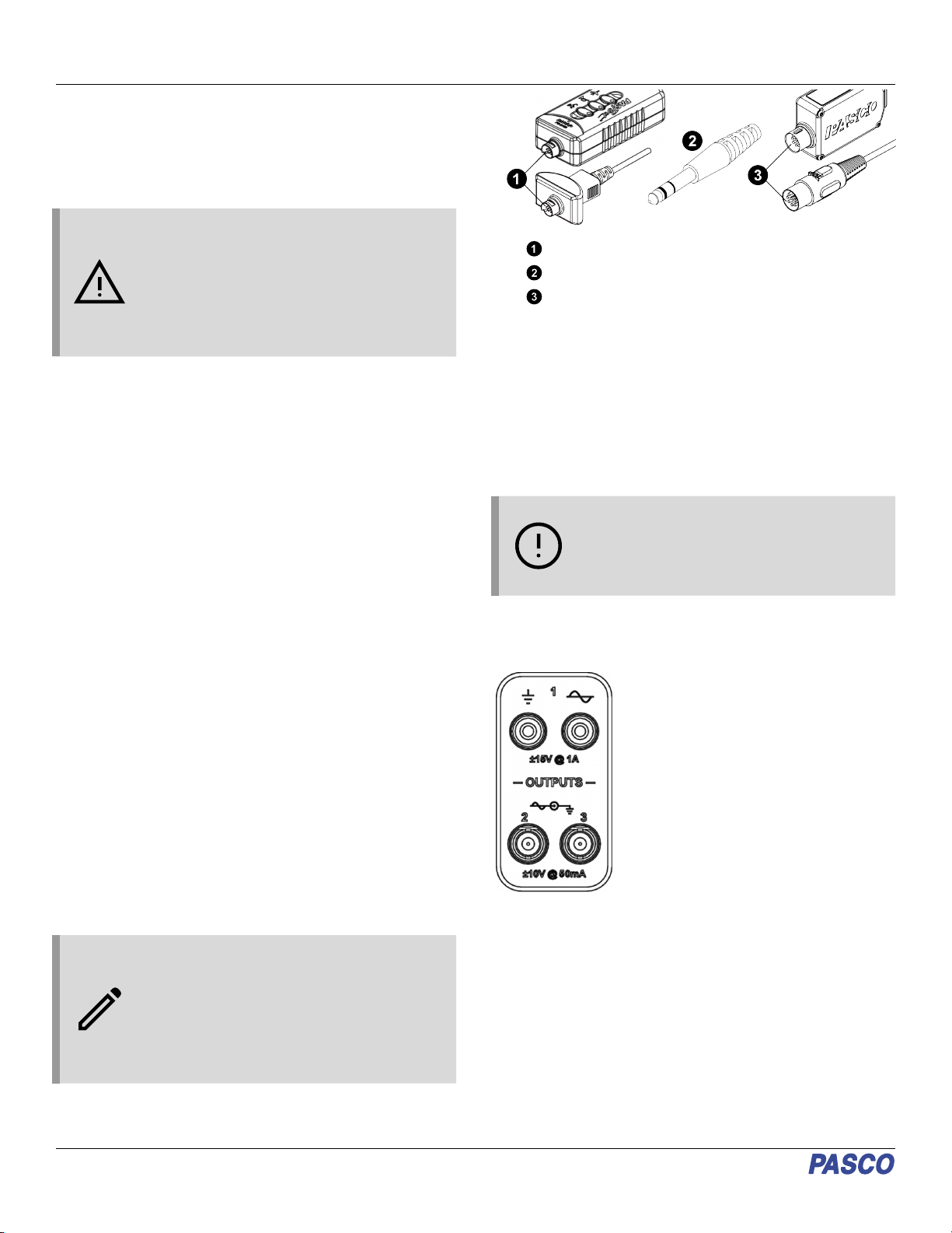
PASPORT plugs
Stereo phone plugs
DIN plugs
Extender cables
If you need extra distance between the sensor and the 850
Universal Interface, use an extender cable such as the 8-Pin
DIN Extension Cable (UI-5218), PASPORT Sensor Extension
Cable (PS-2500), or Phone Jack Extender Cable (PI-8117). Note
that the 8-Pin DIN Cable Assembly included with several
ScienceWorkshop sensors, such as the Light Sensor
(CI-6504A), can also be used as an extension cable, although
Universal Interface sensors specifically require the DIN
Extension Cable (UI-5218).
IMPORTANT: DO NOT connect more than one
extender cable between a sensor and the 850
Universal Interface. Connect the sensor to the
interface either directly or, at most, through one
extender cable.
Using the 850 Interface as a signal
generator The PASCO 850 Universal Interface has
three signal output ports on its front panel.
Output 1 is a signal generator with a built-
in power amplifier. This port has two 4
millimeter (mm) banana jack ports that can
provide ±15 volts at up to 1 amp (or 15
watts) for a variety of AC waveforms
(including sine, square, triangle, and
positive and negative ramps), or direct
current (DC) if needed. The output
frequency range for the waveforms is 0.001
Hz to 100,000 Hz (or 100 kHz), with a
resolution of 0.001 Hz. The output has
over-current detection, voltage offset and
limiting, phase shift, selectable current limiting (0.55 A, 1.10 A,
or 1.5 A), and a frequency sweep function.
Outputs 2 and 3 are signal generators with BNC connectors that
can provide ±10 V at up to 50 mA (or 500 mW) for the same
waveforms as Output 1. The frequency range for these ports is 0
to 500,000 Hz (500 kHz) for the sine wave, with lower maximum
frequencies for the other waveforms and a resolution of 0.001
Hz for all waveforms. These outputs have voltage limiting, phase
shift, and a frequency sweep function.
The output for all three signal generators is controlled by PASCO
Capstone software. The interface can measure the output
voltage, frequency, and peak amplitude for all three output ports,
as well as the output current for Output 1.
850 Universal Interface | UI-5000
2


