pass & seymour PTWSP-250 User manual

TROUBLESHOOTING
Load will not turn on:
• LEDdoesnotash:
-Ifthesensorfailstooperateaftertheinitialwarm-upperiod,useasmall
atbladescrewdrivertopryoffbuttonandslidethelinepowerreversing
switchtotheoppositeposition.Thiswillre-initiatethewarm-upperiod.
-Checkthesensitivityforproperconguration.
-Checkallwireconnections.Verifythegroundwireistightlysecured.
• LEDdoesash:
-PresstheON/OFFbutton.Ifloaddoesnotturnon,checkallwire
connectionsandverifytheloadwireistightlysecured.
-Checkthelightleveltrimpot.Turnitfullyclockwise
• Ifloadstilldoesnotturnon,call800.223.4185fortechnicalsupport.
Load will not turn off:
• Thetimedelaycanbesetfor30seconds
(WalkTest),5,10,15,20,25,or30
minutes.Ensurethatthetimedelayis
settothedesireddelayandthatthereis
nomovementwithinthesensor’sview
forthattimeperiod.
• Toquicklytesttheunitforproper
operation,turnthetimedelayto
minimum(fullycounterclockwise)and
moveoutofthesensor’sview.Load
shouldturnoffafter
30seconds.
• Ifloadstilldoesnotturnoff,call
800.223.4185fortechnicalsupport.
Sensing motion outside desired area:
• Opaqueadhesivetapeisincludedwiththesensorandcanbeusedtolimitthe
detectionareas.SeeMaskingtheLens.
• Adjustsensitivitycounterclockwisetoreduceexcessivesensitivity.
PTWSP‑250
PlugTail™Passive Infrared Wall Switch
Occupancy Sensor
SPECIFICATIONS
PTWSP-250 Voltages............................................120or277VAC,60Hz
LoadRequirements
@120VAC,60Hz............. 0-800Wballast&tungsten,1/6hp
@277VAC,60Hz........................................... 0-1200Wballast
TimeDelayAdjustment...................................30seconds-30minutes
SensitivityAdjustment...........................................Minimum-Maximum
LightLevelAdjustment..................................................... 10-200+FC
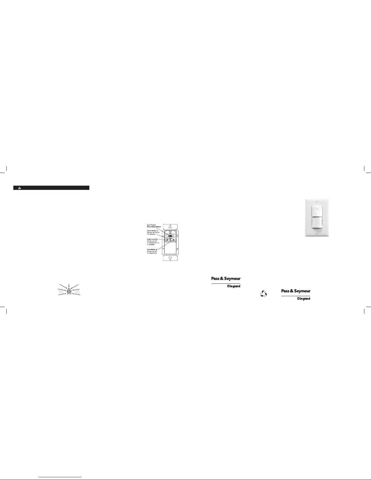
SENSOR ADJUSTMENT
DO NOT OVERTURN TRIMPOTS WHEN ADJUSTING THE SENSOR!
1. Totestunitoperation,presstheON/OFFbuttontoturntheloadon.
2. Removethebuttoncovertoaccesstheadjustmentcontrols.Useasmall,
atbladescrewdrivertopressdownthelockingtabatthetopofthebutton,
thengentlypryitoff.
a)Setthetimedelaytothe“walktest”position(fullycounterclockwise).
b)Leavetheroom.Theloadshouldgooffafter30seconds.
3. Totestsensitivity:
a) Makenomotionfor3seconds.
b) Waveyourhandsidewaysinfrontofthesensoratadistanceof
approximately12".TheLEDblinkswhenmovementisdetected.
Typically,thesensitivityshouldbeatmaximum(fullyclockwise).
4. Setthelightlevelwhenthecontrolledlightwouldnormallybeturnedoff
duetothepresenceofsufcientdaylightorotherelectriclight.[Ifthis
featureisnotneeded,leavethelightlevelatmaximum(fullyclockwise)].
a) SettheTimeDelaytoatleast5minutes.Thistakesthesensoroutof
Walk-testmode,andenablesthelightlevelfeature.
b) SettheLightlevelto50%(12o’clockposition)whichisapproximately
100fc.Letthesensortimeoutsolightsareoff.Enterthespaceand
lightsshouldremainoff.
c) Makesureyourbodydoesnotcastashadowonthesensor,andadjust
thelightleveltrimpotclockwiseinsmallincrements.
d) Aftereachadjustment,wait5-10secondstoseeifthelightsturnon.
Repeatuntilthelightsturnon.Atthissettingtheloadconnectedtothe
sensorwillnotturnoniflightlevelsareabovethecurrentillumination.
Note: Userscanoverridethisfunctionbyplacingtheirhandinfrontofthe
sensortoblockincominglight.Theloadwillthenremainonuntilthe
spaceisunoccupiedorthelightlevelrisesabovethesetpointandthe
timedelayexpires.
5. Resetthetimedelaytothe
desiredsetting.Thetimedelay
canbesetfrom30seconds
(seeWalk-testfeature,light
levelfeatureisdisabled)
to30minutesin5-minute
increments.
Call 800.223.4185 for Technical Support
WARRANTY INFORMATION
Pass&Seymour/Legrandwarrantiesitsproductstobefreeofdefects
inmaterialsandworkmanshipforaperiodofve(5)years.Thereare
noobligationsorliabilitiesonthepartofPass&Seymour/Legrandfor
consequentialdamagesarisingoutof,orinconnectionwith,theuseor
performanceofthisproductorotherindirectdamageswithrespecttolossof
property,revenueorprot,orcostofremoval,installationorreinstallation.
Installation Instructions
P.O.Box4822,Syracuse,NY13221-4822
TechnicalSupport:800.223.4185
www.legrand.us
340914
Please
Recycle
Visit our website: www.legrand.us
Time Delay (T)
Shown as set for
15 minutes
30 seconds
(Walk-test)
5 minutes
10 minutes 20 minutes
25 minutes
30 minutes
LTS

UNIT DESCRIPTION AND OPERATION
ThePTWSP-250WallSwitchOccupancySensorsturnlightingorfanloads
onandoffbasedonoccupancyandambientlightlevel.Theyaredesignedto
replaceastandardlightswitch.ThePTWSP-250operateswith120or277VAC
linevoltage.
Thesensorusespassiveinfraredtechnologytosensehumanmotion,and
definesitasoccupancy.AgreenLEDonthesensorblinksuponoccupancyand
thenresets.Itwillblinkagainwhenitdetectsmotionafterthe2-secondreset.
Thesensorturnsontheloadautomaticallywhenitdetectsoccupancy.Oncethe
spaceisvacantandthetimedelayelapses,itturnsofftheloadautomatically.
Ifadequateambientlightisalreadypresentinthearea,thesensorwillhold
offtheloaditcontrols.Whenthelightdropsbelowafieldselectableleveland
thesensordetectsoccupancy,thesensorturnsontheload.Onceturnedon,
theloadremainsonuntilthespaceisvacantorthelightlevelrisesabovethe
setpointandthetimedelayexpires.
Manual Operation: TheoccupantcanpresstheON/OFFbuttontoturntheload
onandoff.Whentheloadisturnedofforonmanually,itstaysofforonaslong
asthesensordetectsmotion.Afternomotionisdetectedforthelengthofthe
timedelay,thesensorgoesbacktoautomaticoperation.Iftheloadwason,it
turnsoff.Thenexttimethesensordetectsoccupancyandtheambientlightis
lowerthanthesetlevel,thesensorautomaticallyturnsontheload.
Walk‑test feature:
WhentheTimeDelay
trimpotisinthefully
counterclockwiseposition,
thesensorhasa30second
timedelayandtheLight
Levelfunctionisdisabled.
Thisallowsyoutoquickly
checkthesensorcoverage
area.
Override function:
Intheeventofunitfailure
orifitisnecessarytoleave
theloadon,removethe
OverrideJumperplug.This
disablesallautomaticonand
offfunctionsandtheloadcan
onlybeoperatedusingthe
ON/OFFbutton.
COVERAGE PATTERNS
ThePTWSP-250detectsmotioninareasupto900sq.ft.andupto35feet
fromthesensor.Ideally,thesensorisdesignedforsmallamountsofmotion
inspacesupto300sq.ft.TheFresnellensonthesensorisamultiple
segmentviewinglenswithafieldofviewof180°.
Thesensormusthavea
clearviewofthepeoplein
thespaceinordertodetect
occupancy.Obstructions,
suchasfurnitureblocking
thesensor’slens,may
preventoccupancy
detection.
15'
(4.6m)
35'
(10.7m)
4.0'
(1.2m)
35'
(10.7m)
floor
Masking the lens
Opaqueadhesivetapeissuppliedsothat
sectionsofthesensor’sviewcanbemasked.
Thisallowsyoutoeliminatecoveragein
unwantedareas.
Sincemaskingremovesbandsofcoverage,
remembertotakethisintoaccountwhen
troubleshootingcoverageproblems.
1. IfPTSSeriesConnectoralreadyexistsinwalljunctionbox,verifyconnectoris
wiredasstatedbelow:
BlackWire(Connector) To LineHotWire(BranchCircuitWiring
BlackWire(Connector) To LoadWire(BranchCircuitWiring
GreenWire(Connector To GroundWireorGroundSystem
(BranchCircuitWiring)
IfthisisanewinstallationandthereisnoexistingPTSSeriesConnectorin
thewalljunctionbox,thenwireaccordingtothediagrambelow.
Note: ConnectormustbeinstalledperNECandshallbeperformedbya
qualifiedelectrician.
UseonlyP&SPSTSeries™Connector.Donotconnectordisconnectunder
load.
2. SnapconnectorintoPTWSP-250deviceasshown.
3. Verifyconnectorsecurityandengagement.
4. Attachthesensortothewallbymountingitinthewallboxwiththetwo
mountingscrewsprovided.
5. Turnonpoweratthecircuitbreaker.
There is an initial warm‑up period after installation.Itmaytakeuptoa
minutebeforetheloadturnsonduetoasensorwarm-upperiodduring
initialpower-up(thisoccursduringinstallationonly).Theloadturnsonafter
thewarm-upperiodendsifthesensordetectsmotion.
Ifthesensorfailstooperateaftertheinitialwarm-upperiod,useasmall
atbladescrewdrivertopryoffbuttonandslidethelinepowerreversing
switchtotheoppositeposition.Thiswillre-initiatethewarm-upperiod.
CAUTION
Turn the power off at the circuit breaker before installing the sensor.
INSTALLATION
Call 800.223.4185 for Technical Support Call 800.223.4185 for Technical SupportVisit our website: www.legrand.us Visit our website: www.legrand.us
Side View
Top View
Opaque tape
Rapid successive pressing of the ON/OFF button causes a delay in function.
Asinglepressofthebuttoncausesanimmediateresponse.Ifthebutton
ispressedagainwithin2seconds,theswitchignoresit.Waitatleasttwo
secondsbetweenbuttonpresses.
6. TestthesensorusingtheprocedureintheSensorAdjustmentssection.
7. Replacewallswitchcoverplate.
Maximum = clockwise
Minimum = counterclockwise
ViewShowing
RearofSensor
Insert
Verify snap
engagement

REV DESCRIPTION INT: REV. DATE APPROVED
1 PTWSP-250InstSheet ML 17Jan11
TITLE BOX PAGE ONLY.
DO NOT MAKE FILM • DO NOT PRINT
MATERIAL:White80g/msq
Uncoated,preferrecycledstock
INK: Black
PRINT: 2sided
FLAT (cut) SIZE: 16"Wx6"H
FOLDED SIZE: 4"Wx6"H
AllinformationinthisdrawingisthepropertyofPass&Seymour/
Legrandandcannotbecopiedorusedwithoutthewrittenapproval
ofPass&Seymour/Legrand.
Title:PTWSP-250
InstallationInstructions
SYRACUSE, NEW YORK
DRAWN BY
PLM
MARCOM
ENGINEERING
QA
TITLE BOX PG
Loughlin
SCALE1:1
Drawing #: Orig. Drawing Date: 22Dec10
Revision Date:17Jan11
REV. #:
1
Other pass & seymour Switch manuals

pass & seymour
pass & seymour RT-24 User manual

pass & seymour
pass & seymour RW500U User manual

pass & seymour
pass & seymour WDT-200 User manual

pass & seymour
pass & seymour OSR300S User manual

pass & seymour
pass & seymour WSP-250 User manual

pass & seymour
pass & seymour RWU600U User manual

pass & seymour
pass & seymour RWDU500 User manual

pass & seymour
pass & seymour RW3U603 User manual
Popular Switch manuals by other brands

Minicom
Minicom Smart 4 user guide

Pretorian
Pretorian EnvirON Switch 125 instructions

Russound
Russound A-H2 installation manual

MIIDEX LIGHTING
MIIDEX LIGHTING Vision-El ELV412966 Notice Instructions

Asante
Asante IntraCore 35516 Series user manual

D-Link
D-Link DGS-3212SR Command line interface reference manual