PATHFINDER PsT 900 User manual

PsT 900
PsT 900XS
Installation Instructions
LED Floodlight
PLED18-900-8
PATHFINDER
LED
Lighting the way
2020 Pled Australia Pty Ltd. All rights reserved. For informational purposes only

PLEASE READ THESE INSTALLATION INSTRUCTIONS CAREFULLY BEFORE INSTALLING THIS
EQUIPMENT.THEPRODUCTISDESIGNEDFORINSTALLATIONINACCORDANCEWITHRELEVANT
AUSTRALIAN STANDARDS (AS3000) AND LOCAL REGULATIONS (WHERE APPLICABLE), BY AN
AUTHORISEDANDLICENCEDELECTRICIAN.
THE PRODUCT MUST BE OPERATED IN ACCORDANCE WITH THE MANUFACTURER’S INSTRUCTIONS AND
LIMITATIONS,FAILURETODOSOMAYDAMAGETHEPRODUCTANDSHORTENITSSERVICELIFE.
24/7 USE OF PRODUCT WITHOUT THE APPLICATION OF SUITABLE SWITCH CYCLE INTERVALS IS NOT
RECOMMENDED. PRODUCT DESIGN HAS BEEN OPTIMISED FOR A CONTINUAL DAILY USAGE OF 17 HOURS IN
COMMERCIALANDINDUSTRIALAPPLICATIONS.
THE PRODUCT HAS BEEN DESIGNED FOR LOW MAINTENANCE AND IS SELF CLEANING IN REGIONS WHERE
ADEQUATE NATURAL PRECIPITATION OCCURS. IN EXTREME HOSTILE ENVIRONMENTS HOWEVER, ESPECIALLY,
REGIONS OF HIGH ATMOSPHERIC PARTICULATE CONCENTRATION, SUITABLE CLEANING SCHEDULES SHOULD
BEIMPLEMENTEDINORDERTO PRESERVEUSEFULLIFETIMEEXPECTATIONS.
COMPLETIONOFTHEATTACHEDPOSTINSTALLATIONCHECKLIST
ISMANDATORYINORDERTOACTIVATEWARRANTY
Removal From Carton
Lifting Point Lift unit vertically until
clear of carton
Carton Gross Weight (Luminaire) 15.2kg
Luminaire Weight 13.3kg
Driver module Weight 8.0kg
Carton Gross Weight (Driver) 9.0kg
DO NOT LIFT UNIT VIA
THE INTER-WIRING
GALLERYASSEMBLY
PLED18-900-8
2020 Pled Australia Pty Ltd. All rights reserved. For informational purposes only
PATHFINDER
LED
Lighting the way

Carton Contents
PST900/XS LED Module
PST900/XS LED Module Principal Dimensions
PS001_5Z_DR003B
M6 x 16
ISO 7380 FL
SS Screws x 4
PDM2I600-PS900
Driver Module
PLED18-900-8
339,00
428,00
92,00
178,00
292,00
520,00
2020 Pled Australia Pty Ltd. All rights reserved. For informational purposes only
PATHFINDER
LED
Lighting the way

PST900/XS LED Module Mounting Detail
For Mounting Use One M20 Hex Bolt
Azimuth lock with One M12 Hex Bolt
Min. Grade 8.8
G
The unit is cooled by convection
DO NOT Install with Gravity
vector perpendicular to Fin Plane
PLED18-900-8
80,00
12,00
20,00
36,00 72,00
Azimuth
Pivot
R264,00
0
Tilt 0.0
125,00°
86,00°
2020 Pled Australia Pty Ltd. All rights reserved. For informational purposes only
PATHFINDER
LED
Lighting the way

312,00
140,00
72,00
36,00
143,00
40,00
12,00
20,00
76,50
68,00
Driver On Board Arrangement
PS001_5Z_DR003B
Mounting Bracket
Co-Bolt Bracket to
structure with luminaire
Install PDM2I600-PS900
Driver Module using 4 x M6
Flanged screws
M6 x 16
ISO 7380 FL
SS Screws
PLED18-900-8
PDM2I60-PS900 Driver Module On-Board Mounting
201,00
237,00
Choose pivot hole, rotate driver module to
desired position, Torque retaining fasteners.
Interconnect units using appropriate Liquid
Tight glands and conduit(Not Supplied)
2020 Pled Australia Pty Ltd. All rights reserved. For informational purposes only
PATHFINDER
LED
Lighting the way

PDM2I60-PS900 Driver Module Remote Mounting
PLED18-900-8
G
CAUTION:
The driver module is designed to cool by
natural convection and consequently,
when mounted inside a cabinet or
enclosure, must be mounted vertically. It is
also imperative that the enclosure be
adequately ventilated.The case
temperature of the module must be
0
maintained at or below 75 c when running
at max output otherwise the useful life
expectancy will be severely degraded and
the warranty rendered void.
To ensure compliance with this limitation
sample measurements of driver case Tc
must be taken post installation and
recorded on the warranty checklist
document.
Typical ‘Unistrut’ Set Up
Interconnect units using appropriate Liquid
Tight glands and conduit(Not Supplied)
109,00
44,00
262,00
312,00
242,00
37,00
198,00
206,00
44,00
Tc Measurement point
31mm
OUTPUT
170mm
OUTPUT
2020 Pled Australia Pty Ltd. All rights reserved. For informational purposes only
PATHFINDER
LED
Lighting the way

PST900/XS Wiring Detail
Output Junction Box
Input Junction Box
LE Input Junction Box
Recommended interconnection cable (Remote Mount)
2
4 Core 2.5 mm Max Length 80 Metres
Recommended interconnection cable (Driver On Board)
2
4 Core 1 - 1.5 mm Max Length 5 Metres
AC Input can be split into two channels if
individual switching is desired
PST900/XS Light Engine
Junction Box
The PST 900/XS Light Engine module is designed
solely for use with its associated PDM2I60-PS900
Driver Module.
DO NOT CONNECT TOANY OTHER SUPPLY
CAUTION: DC Input polarity critical. Continuous
or momentary reverse polarity will irreparably
damage the LED COB and void warranty
PLED18-900-8
BROWN
BLUE
+
-
OUTPUT 1
BROWN
BLUE
+
-
OUTPUT 2
Control 1
Control 2
BROWN
BLUE
DRIVER 1
INPUT 1
DRIVER 2
INPUT 2
GRN/YEL
ACTIVE
NEUTRAL
EARTH
BROWN
BLUE
GRN/YEL
M20 x 1.5mm
M25 x 1.5mm
BLK/WHT(V )
AUX
PURP(DIM +)
GRY(DIM -) DIM2 -
DIM2 +
2Vaux
BLK/WHT(V )
AUX
PURP(DIM +)
GRY(DIM -) DIM1 -
DIM1 +
1Vaux
2+
2-
1+
1-
DIN Rail
Ground
All junction boxes are designed to facilitate
25 x 1.5 mm & 20 x 1.5 mm liquid tight
conduit fittings. Any fittings employed must
conform to IP67
RED
BLCK/WH
INPUT 1
+
-
INPUT 2
+
-
RED/YEL
1+
1-
2+
2-BLK/YEL
2020 Pled Australia Pty Ltd. All rights reserved. For informational purposes only
PATHFINDER
LED
Lighting the way

Specifications
2 2
Inrush Current(I t) 4.70 A s
Per Channel At 220Vac
input, 25?cold start
Duration = 7.64 ms,
10%Ipk-10%Ipk.
Dimming is achieved by placing an
active 0-10V voltage source, a PWM
signal, or passive component like a
resistor or zener across
If dimming is not required, Dim + should
remain open.
Dim +
(PURPLE) and Dim- (GREY)
Dimming Connections
Positive logic Negative logic
Casambi enabled modules are equipped with the CBU-ASR twin
channel Bluetooth dimming controller built into the driver assembly.
Once connected, the luminaire assembly will be visible to the
Casambi smartphone app. and may be integrated into a network in
accordance with Casambi operating protocols.
For complete information on the Casambi system and its operation
log on to https://casambi.com/products/CBU-ASR.html
PLED18-900-8
2020 Pled Australia Pty Ltd. All rights reserved. For informational purposes only
PATHFINDER
LED
Lighting the way

Aiming The PST900/XS Light Engine
The PST900/XS must be aimed in Azimuth and Elevation precisely in accordance with the
appropriate site lighting plan specifications. Azimuth values are set using a suitable
protractor to establish the desired relative angle between the pole zero reference and the
luminaire reference(Meausured from any longitudinal mounting trunnion face).
Elevation values are set using the onboard inclinometer.
The luminaire may also be aimed visually by gunsight alignment of two external features on
the heat sink body
Luminaire orientation with
0
inclinometer set to 0
Elevation Adjustment
Inclinometer Azimuth Reference
Face
PLED18-900-8
90,00°
Torque trunnion Nuts to 107Nm.
Luminaire utilises low sail area with
a multi friction surface mounting
trunnion and has been designed to
AS/NZS60598.2.5:2002 Region C,
Terrain Category 2 Wind Loading,
for wind speeds up to 250Km/H at
a mounting height of 30m.
Original sighting parameters will be
maintained negating the
requirement for re-aiming to
original lighting design in the event
of such an occurrence.
Index Notch
2020 Pled Australia Pty Ltd. All rights reserved. For informational purposes only
PATHFINDER
LED
Lighting the way

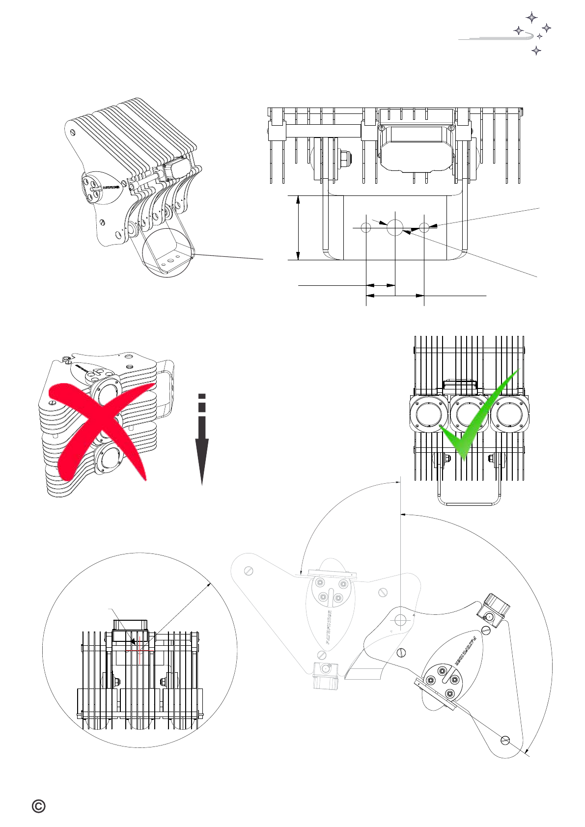
Visually Aiming The PST900/XS Light Engine
PLED18-900-8
Gunsight Notch
Gallery Tube
In the absence of detailed lighting plan
data the luminaire may be crudely aimed
using two visual references on the main
body, namely the gallery tube and a
notched gunsight mark on the forward
faceplate.
This method is adequate for symmetrical
optics however, it is only approximate
with asymmetric optics and correct
verification will need to be conducted
during the hours of darkness with a lux
meter.
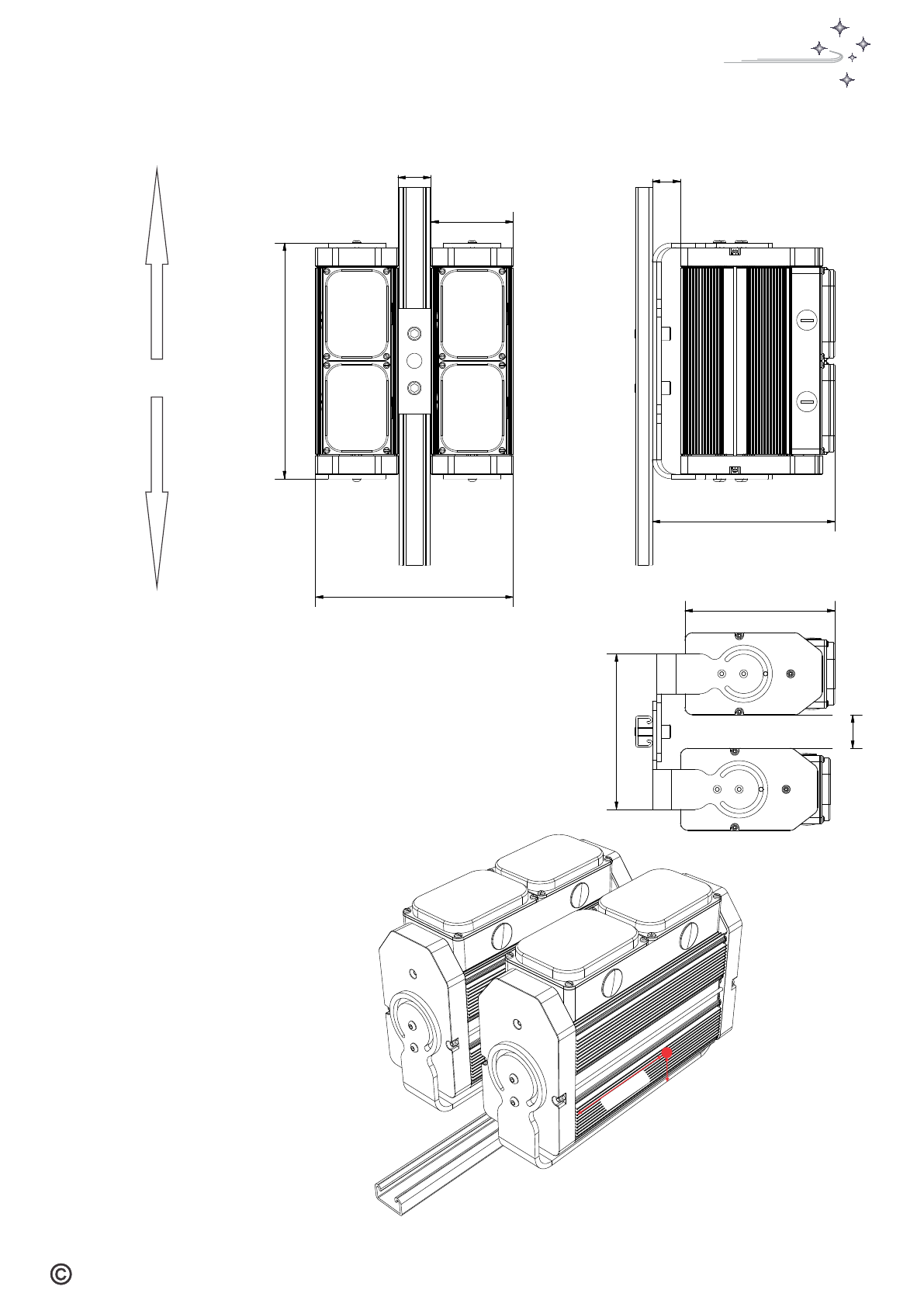
In areas sensitive to light pollution it is
highly recommended to obtain accurate
aiming data and set the luminaire
accordingly
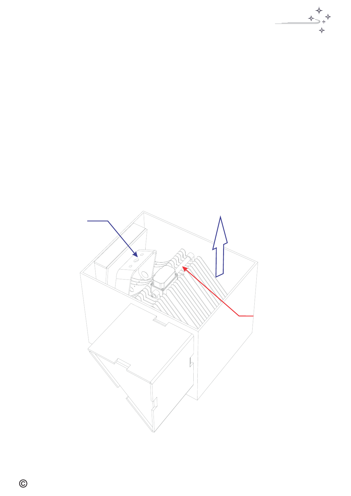
Loosen trunnion nuts and bracket
mounting bolt. Rotate luminaire
until target can be viewed in the
notch between the forward face-
plates, Tilt luminaire until target is
aligned with the bottom of the
gallery tube and the gunsight mark
as shown. Re-Torque fasteners
2020 Pled Australia Pty Ltd. All rights reserved. For informational purposes only
PATHFINDER
LED
Lighting the way
‘Pathfinder’ manufactured by:
Pled Australia Pty Ltd
Ph: +618 9248 2183
Fax: +618 9209 3457
36 Harris Road,
Malaga,
Western Australia 6090
PATHFINDER
LED
Lighting the way

WARRANTY
All Pathfinder products are inspected, tested, and aged before
shipment and are warranted to be free of defects in material or
workmanshipfor aperiodofTenyears forLightEngineHeat Sink
and Mounting products, Five years for Driver products, and Five
years for LED Chip On Board (COB) products from date of
invoicefromPLEDAustPtyLtd(Manufacturer).
Within the first three years of invoice date any such defective
productswillbereplacedatthe option ofPLEDprovidedawritten
claim is made within this warranty period. Following expiration of
the initial three year period products will be repaired or replaced
attheoptionof PLED.
This limited warranty may be extended at no extra cost, to
suitably qualified customers , up to a maximum of ten years for
the entire product, provided that they undertake a ‘Suitability for
Application Assessment’ and execute professional industrial
installation protocols and certify for those protocols by
completing, certifying, and forwarding the Pathfinder installation
checklist. Blank copies are attached to every set of product
installationinstructions
ProductsmeangenuinePathfinder,solidstatelightingproducts.
ŸThe warranty is valid for the entire assembly consisting of:
Heat sink and supporting structure, Appropriate Driver, and
AppropriateCOB.
ŸThestandardperiodisdeemedtocommencefromthedateof
purchase (date of Invoice) from PLED and consists of the
following: Heat sink and supporting structure - 10 Years,
Driver-5Years,ChipOnBoard-5years
10 year total Warranty extension will be activated, upon receipt,
by PLED of a suitability assessment and a correctly executed,
postinstallationchecklist.
COVERAGE
PLEDwarrants to thepurchaser thateach productmanufactured
and sold by it will be free from defects in material and
workmanship in its intended use for the periods stated above
from date of purchaser's purchase (the invoice date) from PLED.
Warranty strictly limited to Purchaser. If any product covered by
this warranty is returned by purchaser in accordance with PLED
Products Return Policy, including without limitation its return
authorisation provisions, within the applicable warranty period
set forth above, and upon examination PLED determines to its
satisfaction that such product was defective in material or
workmanship at the time of delivery to the purchaser, PLED will,
at its option, repair or replace the product or the defective part
thereof.
If PLED chooses to replace the product and is not able to do so
because it has been discontinued or is not available, PLED may
replaceitwithacomparableproduct.
Where defects in materials, manufacturing or design cause the
product/solution failure, they shall be repaired or replaced (at
PLED discretion) according to the most practical resolution for
thecustomerasagreeduponbybothparties.
INCLUSIONS
EXCLUSIONS
Thislimitedwarrantydoesnotcoverthefollowing:
ŸWearandtear andloss of performanceresulting from normal
authoriseduse
ŸProduct failure caused by faulty, erratic, or sub-standard
mains supply power, excessive supply voltage or current
spikes, reverse polarity or overheating caused by improper
installation,omissionofpartsormisapplication.
ŸFailure caused by intermittent or continuous exposure to
vibration, impact, aggressive chemicals and other abnormal
physicalstress.
ŸFailure caused by fires, misuse, accidents, abuse, neglect,
mishandling, misapplication, improper handling/ installation
incurred by the user/installer or Acts of God (such as
lightning, sandstorms or Solar Flare induced fluctuations in
electricalpower).
ŸProducts which have been modified or have had the
identification label and/or the tamper proof label altered,
defacedorrenderedillegible.
ŸFailure arising from the attachment or insertion into the
productofanythirdpartyfixturesorfittings
ŸProduct is left operating in conditions/ requirements other
thanthosementionedinrespectiveproductbrochuresoruser
manuals
ŸThe product has been serviced or modified by personnel not
authorised by Plum LED and extends to replacement of third
partycomponentsnotsuppliedbyPlumLED.
ŸThe product has been provided to the purchaser free of
chargeundergoodwill
Purchaser shall convey with each Product distributed to end
usersthisMANUFACTURER'SLIMITEDWARRANTY
LIMITATIONS AND CONDITIONS
This is a limited warranty, and excludes installation and
consequential damages (such as loss of revenue/profits,
damage to property or other extended costs not previously
mentioned), and is further defined by the limitations and
conditionsbelow.
PLED shall not be liable for any loss of use of the equipment,
inconvenience, or any other damages, whether direct, indirect,
incidental or consequential resulting from the use of this product,
oraspiringoutofanybreachofthiswarranty.Thelimitedwarranty
and remedies set herein are exclusive and in lieu of all other
warranties whether statutory, express or implied including all
warranties of merchantability and fitness for particular purpose
and wall warranties arising from course of dealing or usage of
trade. No person, agent, distributor, dealer or company is
authorised to change, modify or extend the terms of this limited
warrantyinanymatterwhatsoever.
For purposes of clarity, "repair or replace the Product or the
defective part there of" does not include any reinstallation costs
or expenses, including without limitation labour costs or
expenses. Products/Solutions should be used within their
specifications (e.g. Temperature, water ingress and other
extremeconditions, Indoor/outdoor, and accordingto application
guidelines. Warranty becomes void if the product is mis-applied.
Warranty will also be voided should the customer fail to
appropriatelymaintaintheirinstallation.
This warranty applies only to the repair or replacement of the
product and only when the product is properly handled, installed
and maintained according to PLED instructions. Purchaser must
notifyPLEDinwritingwithin30daysofnoticingthedefect.
PLED does not warranty voltage/under-voltage and Ripple
Currentcontrolsystemsthatarebeyondthespecifiedlimitsofthe
productsandthosedefinedbyrelevantsupplystandards.
Manufacturer reserves the right to make the final decision on the
validityofanyguaranteeclaim
Luminaire Fixture Warranty Statement
MAKING A CLAIM
Within the warranty period and within thirty days of defect
discovery purchaser must contact PLED or its representative, in
writing,toreceiveaPWC(PendingWarrantyClaim)authorisation
number. Products must be returned, at purchasers expense, to
PLED accompanied by original proof of purchase for fault
assessment.
All transportation and associated costs relating to the delivery of
both faulty and repaired components to the purchaser will be
borne by the purchaser. Upon testing and inspection of the
returned products by PLED, if such products are found to be
defective and such defect has not been caused by reasons
outlinedin thisdocument thenPLEDshall repairor replace,at its
option,saidproduct.
2020 Pled Australia Pty Ltd. All rights reserved. For informational purposes only
PATHFINDER
LED
Lighting the way

Pathfinder Series Installation Checklist
LED technology is significantly different to legacy MH, HID, and Sodium technologies and is
easily damaged if incorrect installation techniques are applied. The following post Installation
checklist must be completed and certified for by the installing technician or contractor. Execution
of this form is mandatory in order to activate cover under the current product warranty statement.
1
Item Action
Instruction Manual Read and Understood
Technician Name Initials
2Grade 8.8 Main Pivot bolt and Lock bolt Installed.
CAUTION: In designated high wind areas at least one lock bolt must be installed
3Driver/Luminaire interconnect cables, correctly graded,
identified, and connected polarity Cross Checked.
CAUTION: LED Chip On Board is highly sensitive to reverse polarity. Even a few
seconds of reverse polarity can irreparably damage the chip and severely shorten its
life. All cables must be unambiguously identifiable and connected in accordance with
the published wiring instructions. Any accidental reverse polarity exposure must be
reported.
4All Cable and conduit entries meet IP66 minimum and
correct installation verified
5Driver and Luminaire interconnection box seals undamaged
with lid screws torqued uniformly
6Driver units correctly mounted in a suitable enclosure in
accordance with installation instructions.
CAUTION: Drivers rely on convective air currents for cooling and must be mounted
vertically with a minimum adjacent spacing of 50mm in a suitably ventilated enclosure
7Driver enclosure temperature measurement:
Data to be collected after one hour continuous operation at Max Power Output.
Record 1. Internal Air Temperature
2. Ambient Temperature
3. Number of driver modules per enclosure
4. TotalAC current draw for enclosure.
NOTE: With multiple enclosure the test need only be conducted once if all
installations are identical. If multiple tests are required use the back of the form to
record the data
8Pivot trunnion bolts torqued to a minimum of 107Nm.
The luminaire utilises multiple friction surface mounting. Correct torquing of the tie
bolt, Post Aiming, is necessary to maintain installed sighting parameters and prevent
damage to the luminaire in an extreme wind velocity event
X Check
I certify that the installation, Job Number Ref: , has been carried out in accordance
with the appropriate Australian and Local Standards, where relevant, and that the above checklist has
been diligently executed with all due care.
Name Company & Title Signature
_______________
___________________ __________________ ________________
Detach and Mail completed form to PLED Australia, 36, Harris Road, Malaga, WesternAustralia 6090
Within 90 days of project completion date
"
Total units & Geographical location of installation(Attach basic site plan if available)
2020 Pled Australia Pty Ltd. All rights reserved. For informational purposes only
PATHFINDER
LED
Lighting the way
This manual suits for next models
1
Table of contents
Popular Floodlight manuals by other brands

Chauvet
Chauvet MegaStrobe FX 12 Quick reference guide

technocraft professional
technocraft professional 310253 quick start guide

Pro-Elec
Pro-Elec PEL00547 instructions

Ruud
Ruud CI285X01 installation instructions

American DJ
American DJ DOTZ FLOOD User instructions

WE-EF
WE-EF FLC200-CC LED Series Installation and maintenance instructions