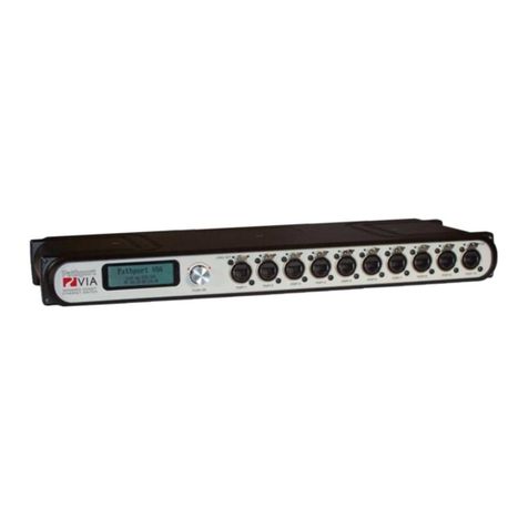
Pathway connectivity solutions Pathport VIA 6730 User manual

Pathport VIA Ethernet Switches
User Guide and Manual
Models running firmware 3.8.0
March 2016
© Acuity Brands Lighting Canada
1439 17 Ave SE Calgary AB T2G 1J9
403-243-8110
www.pathwayconnect.com

Pathway Connectivity
VIA 12 Manual
V3 – April 2015
2
Table of Contents
About Pathport VIA Ethernet Switches............................................................................3
Installation Instructions....................................................................................................3
Panel Layouts .................................................................................................................4
Front Panel – model 6730/6740 ..................................................................................4
Main Display Messages...............................................................................................4
Rear Panel – model 6730............................................................................................5
Rear Panel – model 6740............................................................................................5
Rear Panel – model 6741/6742...................................................................................5
Base Configuration..........................................................................................................6
Network Setup.............................................................................................................7
Device Info/Status.......................................................................................................8
Advanced Settings ......................................................................................................9
VLAN Support .......................................................................................................10
VLAN Setup...........................................................................................................10
VLAN Config/Status: VLAN#..................................................................................10
VLAN Config/Status: Network Settings..................................................................11
VLAN Config/Status: DHCP Server.......................................................................12
VLAN Config/Status: IGMP and Multicast Groups ................................................13
Ring Protect Setup ................................................................................................14
Alternate Art-Net Mapping.....................................................................................15
Quality of Service (QoS)........................................................................................15
Utilities ......................................................................................................................16
Port Status and Configuration Menu..............................................................................17
VLAN Type................................................................................................................18
VLAN ID#..................................................................................................................18
Art-Net to sACN ‘Trap-and-Convert’..........................................................................19
Port Enable/Disable...................................................................................................19
Port PoE Setup/Status...............................................................................................19
LLDP Link Partner.....................................................................................................20
Port Link Mode..........................................................................................................21
Bandwidth Use..........................................................................................................21
Current Multicast Groups...........................................................................................21
SFP Module (Fiber Ports Only)..................................................................................21
Firmware Upgrades.......................................................................................................22
Software Configuration Tools........................................................................................22
Appendix 1: SFP Fiber Adapter Selection .....................................................................23
Appendix 2: Virtual Local Area Network (VLAN)............................................................24
Definitions .................................................................................................................24
Software Configuration of VLANs.............................................................................24
VLAN Guidelines.......................................................................................................25
Appendix 3: Ring Protection..........................................................................................26
Requirements and Limitations...................................................................................26
Definitions .................................................................................................................26
Software Configuration of Ring Protection.................................................................27
Appendix 4: QoS Settings ............................................................................................28

Pathway Connectivity
VIA 12 Manual
V3 – April 2015
3
About Pathport VIA Ethernet Switches
Pathport® VIA Gigabit Ethernet switches are designed for live entertainment Ethernet
systems, including audio and DMX-over-Ethernet networks. This manual covers models
6730, 6740, 6741 and 6742 running firmware of 3.8.0 or higher.
The VIA Ethernet Switch is intended specifically for signal routing between Pathport
DMX-over-Ethernet nodes, or similar equipment, and Ethernet-aware lighting and audio
control products, such as consoles and controllers and end equipment. A VIA is a
routing device and is not a source of the control protocols or the data being passed.
Switches only provide management control over the data path.
Upgrades implementing further Layer 2 and Layer 3 management features will be
released on the Pathway Connectivity website from time to time. The VIA is easily
upgraded using freely available software configuration tools.
Important: VIA models 6740, 6741 and 6742 only provide hardware support for IEEE
802.3af Power-over-Ethernet (PoE), and do not include a built-in PoE power supply.
To utilize the PoE hardware, an external 48VDC power supply must be connected to the
Speakon connector on the rear of these models.
Installation Instructions
Pathport VIA switches are intended for desktop use, or to be mounted in a standard 19”
equipment rack, using the integral rack ears (model 6741 and 6742) or the included rack
ear accessories (models 6730 and 6740).
For model 6730 and 6740, truss-mount adaptors (#9003) and wall-mount kits (#9002)
are available as accessories.
All Pathport VIA switches are intended for installation in a dry, indoor location.
Operating conditions are 0°C - 40°C; 10-90% relative humidity, non-condensing.
Warning: The AC socket outlet shall be installed near the equipment and shall be easily
accessible.
Warning: This equipment relies on building installation primary overcurrent protection.
Warning: Except for the chassis plug marked for AC input, all ports on the Pathport VIA
12 are intended for low voltage and/or data lines only. Attaching anything other than low
voltage sources to the data ports may result in severe equipment damage, and personal
injury or death.

Pathway Connectivity
VIA 12 Manual
V3 – April 2015
4
Panel Layouts
Front Panel – model 6730/6740
Main Display Messages
Along with its soft label and IP address, the VIA may display optional messages. At
present the messages only report status of the Ring Protection feature, when enabled.
Message Explanation
Ring Protect Master: Init Switch configured as Master. Ring is initializing
Ring Protect Transit: Init Switch configured as Transit. Ring is initializing
Ring Protect Master: OK Switch configured as Master. Ring is intact
Ring Protect Transit: OK Switch configured as Transit. Ring is intact
Ring Protect Master: Failed
Switch is configured as Master.
Link between two ports has failed.
Communication now relies on secondary links.
Fault should be located and repaired immediately
Ring Protect Transit: Failed
Switch is configured as Transit.
Link between two ports has failed.
Communication now relies on secondary links.
Fault should be located and repaired immediately
See below for ring protection set up and activation.
PORT 7
ETHERNET SWITCH
MANAGED GIGABIT
VIA
PORT 1 PORT 2 PORT 5PORT 4PORT 3 PORT 6
LINK/ACT
PORT 8 PORT 9 PORT 10
POE
Backlit LCD Screen Rotary Encoder
Turn to highlight item on screen
Push to select
See manual for details
Female RJ45 connectors
Push tab before disconnecting cables
Link\Act
LED Indicator PoE Active
LED Indicator

Pathway Connectivity
VIA 12 Manual
V3 – April 2015
5
Rear Panel – model 6730
Rear Panel – model 6740
Rear Panel – model 6741/6742
Models 6730 and 6740 require the user to provide an SFP (small-form pluggable) fiber
adaptor to allow connectionof the mini-GBIC ports to fiber optic networks. See Appendix
1 for recommendations on SFP adaptor selection.
Models 6741 and 6742 have OpticalCON DUO connectors for LC Duplex Multimode
fiber optic cables installed instead of mini-GBIC ports. Additional SFP adaptors are not
required.
The Powercon plug may be connected to an AC power source with a voltage between
85 and 250VAC, either 50 or 60 Hz. The Speakon plug must only be connected to an
auxiliary Power-over-Ethernet supply not to exceed 48 VDC.
Models 6741 and 6742 have a Powercon THRU connector to simplify mains power
connections in a rack. DO NOT EXCEED 10A DRAW ON THE FIRST SWITCH. The
Powercon jumper cable is not provided.
Risk of electric shock.
Disconnect power
before opening.
Risque de decharge
electrique. Debrancher
le pouvoir avant
d'ouvrier.
90-260VAC
.75A 50/60 Hz
ATTENTION
ERROR
LINK/ACT
PRESENT
Mini-GBIC
SD CARD
48VDC POE
AUX
2.5mm Center Positive
Mini-GBIC Port for
Fiber Optic Adaptor
Auxiliary PoE Input Wide-Ranging IEC Input
90 - 264 VAC 50/60 Hz
48VDC PoE INPUT
200W MAX
Mini-GBIC FIBER OPTIC PORTS
ERROR
LINK/ACT
PRESENT
SD CARD
90-260VAC
.75A 50/60 Hz
Risk of electric shock.
Disconnect power
before opening.
Risque de decharge
electrique. Debrancher
le pouvoir avant
d'ouvrier.
ATTENTION
Female RJ45 Connector
Push tab to release cable
Mini-GBIC Port for
Fiber Optic Adaptor Speakon Connector for
48V Auxiliary PoE Supply
Do NOT connect to high voltage
Powercon Connector for
85 - 250 VAC Input
90-264 0.75A
PORT 11
PORT 12
PORT 13
MULTIMODE
FIBER
Powercon Connector
for AC Input
Powercon Connector
for AC Thru
Speakon Connector
for 48VDC PoE Supply
LC Connector for
Multi-mode Fiber
RJ45 Ethercon
Connector
AUXILIARY
GIGABIT
ETHERNET
AC INPUT
MAX 10A
AC THRU
48-56 VDC
PoE INPUT
200W MAX

Pathway Connectivity
VIA 12 Manual
V3 – April 2015
6
Base Configuration
With the default screen shown on the LCD, press the encoder knob. The base
configuration menu will be shown.
Turn the knob to scroll down the menu. The current menu item is highlighted in reverse
video. Push the knob to enter sub-menus. Top-level menu entries are shown in the
following table below.
Menu Label
Network Setup
Device Info / Status
Advanced Settings
Utilities
<Back>
For all menus and submenus, the current selection will be highlighted in reverse video.
Push the encoder knob to reach further options, or to select the current one. Some
menus, such as Network Settings, require the user to scroll down to accept or discard
any changes made. The ‘Back’ option will always move the menu up one level. The
current menu will time out after approximately thirty seconds.
Note on LCD Lockout: Software configuration tools (see Software Configuration below)
may allow a user to lock out the ability to edit the VIA from the LCD menu. Settings may
only be reviewed. This LCD lock out is disabled after a hard reboot of the switch, for a
rolling thirty second window after reboot is finished. This time window allows changes to
be made when a software connection is not available. It is not possible to completely
disable the LCD lockout from the front panel.
Base Configuration
Network Status
Device Info/Status

Pathway Connectivity
VIA 12 Manual
V3 – April 2015
7
Network Setup
Allows review and changes of the IP address, subnet mask and default gateway. These
settings are the default values for VLAN 1, and will be used if VLANs are disabled. To
edit these properties, push the knob again.
IMPORTANT: If multicast filtering, or a DHCP server is required, DO NOT make
changes to network settings here. Use the Advanced Settings>VLAN Setup>VLAN
Configure menus.
Property
Explanation
IP Mode
Determines how IP settings will be obtained
Static (default for VLAN#1): IP settings manually set by user.
Dynamic: IP settings will be obtained from a DHCP server.
IP Address Manually sets IP address (IPv4)
Turn knob to set each octet. Push to accept.
Illegal values are not accepted.
Subnet Mask Set subnet mask for node. Only valid masks are shown.
Turn knob to select from list of valid masks.
Default Gateway Set default gateway for node. Only valid gateways accepted.
Turn knob to set each octet. Push to accept.
Illegal values are not shown.
IP Mode must be set to “Static” if the VIA is to act as a DHCP server. Setting the IP
Mode to “Dynamic” does NOT enable the DHCP server. DHCP service is enabled under
Advanced Settings>VLAN Setup>VLAN Config>VLAN <#>>DHCP Server.
If the IP Mode is set to “Dynamic” on a system with no active DHCP server, the switch
will auto-generate IP settings in accordance with zeroconf standards, in the IP range of
169.254.x.x/16. This range may not be suitable for connection to entertainment systems.
When IP Mode is set to “Dynamic”, it is still possible to manually adjust the IP settings.
This practice is not recommended as the changes will not stick.
Once the values have been set, acceptance options appear on the bottom line of the
screen. Turn knob to choose from following options.
Option Explanation
Discard Changes Discards all changes and returns to base menu
Save and Apply Saves changes and applies them to VLAN 1, and returns
to Network Setup menu.

Pathway Connectivity
VIA 12 Manual
V3 – April 2015
8
Device Info/Status
Allows review of the following non-editable properties:
Property Explanation
Serial Number Factory-assigned, Pathway serial number
MAC Address Factory-assigned media access control address
Firmware Version Current operating firmware version. Firmware may be
updated using software configuration tools
Ring Protect State
(if enabled)
OK
: Ring is intact
Init: Ring is initializing
Failed: Link between two ports has failed.
Communication now relies on secondary links. Fault
should be located and repaired immediately
PoE Used Total Power-over-Ethernet being drawn by all connected
devices, in watts
PoE Allocated Total current Power-over-Ethernet budgeted to all ports, in
watts
PoE Remaining Total unallocated Power-over-Ethernet available from PoE
power supply, in watts
Back Returns to base menu
IMPORTANT: VIA models 6740, 6741 and 6742 require an external PoE power supply
for PoE to be operational. These models do not have an on-board PoE supply.
VIA model 6730 has 60W of on-board PoE power. This amount may be augmented with
an auxiliary external supply.
For VIA models 6740, 6741 and 6742, the PoE External Supply Power must be manually
configured using Pathway software tools, or PoE will not function. All PoE values will be
reported as 0.0W.

Pathway Connectivity
VIA 12 Manual
V3 – April 2015
9
Advanced Settings
Menu Item Menu Options
VLAN Support Disabled (default)
Enabled. Must be enabled to show VLAN Setup and Ring Protect feature
VLAN Setup
VLAN Range Start: <x> Specifies lowest VLAN ID# available.
Valid range: 1 to 4095. Default is 1.
VLAN Range End: <x> Specifies highest VLAN ID# available.
Valid range: 1 to 4095. Default is 10.
Management VLAN:<x>
Specifies the VLAN ID# used by the
management processor. Default is 1.
This value MUST be within the range specified
by the range start and end set above, or you will
not be able to configure the switch.
VLAN Config/Status VLAN#
Network Settings See below
DHCP Server Disabled (default)
Enabled
IGMP Snooping Disabled (default)
Enabled
IGMP Querier Disabled (default)
Enabled
Current Multicast
Groups See below
Ring Protect
Setup
Ring Protect Mode
Disabled (default). Ring is turned off.
Master: Switch with master responsibility for
monitoring ring. Only one Master is allowed
Transit: All other switches are set as Transit
Primary Port: <x>
Designates which port to use as the active
uplink port to other switches. Valid range is port
11 thru 14 only (models 6740, 6741, 6742) or
ports 9 thru 11 (model 6730).
Secondary Port: <x>
Designates which port to use as the fall back
link to other switches. Valid range is port 11
thru 14 only (models 6740, 6741, 6742) or ports
9 thru 11 (model 6730).
Control VLAN: <x>
Specifies the VLAN ID# used to determine the
integrity of the ring. may not be used for any
other traffic. Valid ID# is any ID outside the
range set in VLAN setup. Default is VLAN 4095.
Alternate Art-
Net Mapping Disabled
Enabled (default).
QoS Settings Off (default)
Standard
Dante Strict

Pathway Connectivity
VIA 12 Manual
V3 – April 2015
10
Plan your VLAN layout before attempting configuration. The creation of a map of the
network, showing which devices and which ports to associate with a given VLAN, is
strongly recommended prior to configuration.
EXTREMELY IMPORTANT NOTE: When configuring one or multiple VIA switches
using Pathway’s software-based configuration tools, be certain all switches are
set to the same Management VLAN ID#. Be certain that the port connected to your
computer is also on the same VLAN ID#. Failure to observe this rule will result in
what appears to be a broken network, and embarrassment upon realizing the
operator error.
For more information on VLANs and definition of terms, see the appendix.
VLAN Support
VLAN support must be enabled to allow access to the Ring Protect feature and to the
VLAN set up and configuration menus. Once Ring Protection is enabled, VLAN support
cannot be disabled.
VLAN Setup
These properties determine the size of the VLAN table, and which VLAN has
communication with the switch’s management processor. For efficient switch operation,
the VLAN range should be kept as small as necessary.
If the Management VLAN is accidentally set to a value outside the VLAN range, it may
be necessary to use the Factory Default Including Net Setup from the Utilities menu, to
restore communication with the management processor and allow further configuration.
The VLAN range and individual VLAN configuration must be done prior to activating the
Ring Protect feature.
VLAN Config/Status: VLAN#
Each VLAN is identified by its VLAN ID#. It is not currently possible to soft label VLANs.
Each VLAN ID# must be configured separately, and each VIA switch must be uniquely
identified on each VLAN in use on that switch. There is currently no way of copying
properties from one VLAN to another.
The VLAN ID# is assigned to individual ports from the Port Configuration Menu.

Pathway Connectivity
VIA 12 Manual
V3 – April 2015
11
VLAN Config/Status: Network Settings
Property
Explana
tion
IP Mode
Determines how IP settings will be obtained
Disabled (default): No IP assigned.
Static: IP settings manually set by user.
Dynamic: IP settings will be obtained from a DHCP server.
IP Address Manually sets IP address (IPv4)
Turn knob to set each octet. Push to accept.
Illegal values are not accepted.
Subnet Mask Set subnet mask for node. Only valid masks are shown.
Turn knob to select from list of valid masks.
Default Gateway Set default gateway for node. Only valid gateways accepted.
Turn knob to set each octet. Push to accept.
Illegal values are not shown.
Network Settings must be configured on any VLAN requiring use of multicast filtering
(IGMP) or a DHCP server. By default, only the management VLAN (VLAN ID#1 by
default) is automatically assigned an IP and subnet mask. All other VLANs default to a
null IP address value (0.0.0.0). From the Network Settings for each VLAN, assign a
unique IP per switch, a common subnet mask and, where necessary, a default gateway.
Default gateway addresses are not typically required on most entertainment installations,
as these systems do not typically connect to the Internet. Any Internet access will be
through a proxy or NAT gateway, in which case the default gateway IP should point to
this device.
IP Mode must be set to “Static” if the VIA is to act as a DHCP server. Only one DHCP
server may be active on any given VLAN. Setting the IP Mode to “Dynamic” does NOT
enable the DHCP server – see below.
If the IP Mode is set to “Dynamic” on a system with no active DHCP server, the switch
will auto-generate IP settings in accordance with zeroconf standards, in the IP range of
169.254.x.x/16. This range may not be suitable for connection to entertainment systems.
When in doubt, we recommend using a mode of ‘Static’ and configuring each switch and
VLAN combination with a unique IP address and appropriate subnet mask.

Pathway Connectivity
VIA 12 Manual
V3 – April 2015
12
VLAN Config/Status: DHCP Server
VIA switches can automatically assign IP addresses to connected devices, using a
DHCP (dynamic host configuration protocol) server.
Important: Only one DHCP server may be active on any given VLAN at one time.
Running multiple DHCP servers will cause network reliability problems.
The DHCP-hosting VIA switch must first be set to a static IP address on the desired
VLAN, prior to enabling the DHCP server. The DHCP server should be enabled prior to
setting other connected devices to a ‘Dynamic IP” mode or being connected to the
network VLAN.
In some cases, it may be necessary to reboot connected devices to ensure the DHCP
server correctly recognizes them and assigns appropriate network settings.
Property Explanation
Disabled DHCP service is turned off. Use this setting for all static
(manually-set) IP systems, and for all switches other than
the VLAN’s designated DHCP server host.
Enabled
Enables DHCP server.
Pool Start: Set the first available IP address.
Pool End: Set the last available IP address.
The DHCP pool is partially predefined based on the IP
address and subnet mask of the host switch, as the host
must have proper communication with the requesting
device. Invalid pool ranges are not accepted.
Server Config
Valid: Pool range is valid and can be applied.
Invalid: Pool range is invalid. Try again.
This property is not user-editable and acts as a check
against accidental surprises.
Enable and Exit Accept the designated pool and start the DHCP service.
Option only available if the Server Config is valid.
Revert and Exit Abandon configuring the DHCP server
Disable Server and
Exit
Turn DHCP server off.
Warning: Devices relying on dynamically obtained IP
addresses require an active DHCP server to function.

Pathway Connectivity
VIA 12 Manual
V3 – April 2015
13
VLAN Config/Status: IGMP and Multicast Groups
When using multicast data packets, such as streaming ACN (sACN), bandwidth
efficiency may be improved by using IGMP (Internet group management protocol) to
enable multicast filtering.
Property Explanation
IGMP Snooping Enable/disable IGMP snooping – allows the switch to
correctly filter multi-cast traffic
IGMP Querier Enable/disable the IGMP querier – creates the multicast
tables used by snooping
Current Multicast Groups Shows the table of multi-cast groups in use on the
VLAN. Click on a group to see which ports are
subscribers to that group.
The IGMP Querier establishes a table of active multicast groups by querying connected
devices about which multicast groups each device wishes to join. For example, a
gateway will request the multicast groups associated with the sACN universes that the
gateway is patched to.
Each switch participating in an IGMP-enabled VLAN must have valid IP settings on that
VLAN. The IP settings may be static or dynamically established using the DHCP.
IMPORTANT: Two IGMP queriers should be active on each VLAN using multicast
filtering. If no querier is active, the groupings table will fail after approximately five
minutes and filtering will only work erratically or will fail altogether. IGMP should not be
enabled on more than four VLANs per switch.
The IGMP Snooper allows the switch to more efficiently route multicast traffic by
applying the multicast groupings as a filter. Multicast traffic is only directed to only those
ports, i.e. end devices, that have requested to receive that traffic.
The Current Multicast Groups is a list of the multicast addresses currently maintained in
the Querier’s table. The list provides a troubleshooting check. Click on a listed group to
see what ports are requesting that address. For example, the multicast groups
239.255.237.1, 239.255.237.2 and 239.255.237.255 indicate traffic between Pathport
devices, and all ports connected to Pathports (on that VLAN) should be shown.

Pathway Connectivity
VIA 12 Manual
V3 – April 2015
14
Ring Protect Setup
This option will only be shown if VLAN support is enabled.
Property Explanation
Ring Protect Mode:
Shows the current state of the switch. Press knob to
change between:
Disabled: Ring Protection feature is turned off
Master: Only one switch may be set as the Master.
Transit: All other switches must be set as Transit.
Primary Port: <x> Designates which port to use as the active uplink port to
other switches. Valid range is port 11 thru 14 only.
Secondary Port: <x> Designates which port to use as the fall back link to other
switches. Valid range is port 11 thru 14.
Control VLAN: <x>
Specifies the VLAN ID# used to determine the integrity of
the ring. This VLAN may not be used for any other
traffic. Valid ID# is any ID outside the range set in VLAN
setup. Default is VLAN 4095.
Save and Apply Returns to base menu
Discard Changes Returns to base menu
Warning: Ring Protection should only be configured and enabled after all other VLAN
configuration has been completed.
During the set up and configuration of the Ring Protection feature, communication
between devices may be erratic or broken. We strongly recommend that all switches be
configured with the appropriate Ring Protection settings PRIOR to be connected
together. We also strongly recommend that all switches be disconnected from one
another PRIOR to disabling the ring feature.
Prior to set up, determine which switch will be the master. Generally, the least busy
switch is the best choice. All other switches must be configured as transit switches.
All switches must have both a primary and a secondary ring port set. These ports will be
automatically configured as Tagged (uplink) ports, meaning all traffic on all VLANs will
be passed through the ports.
If changes are made to the ring configuration while the ring is active, it may be
necessary to reboot all switches for the changes to take effect.

Pathway Connectivity
VIA 12 Manual
V3 – April 2015
15
Alternate Art-Net Mapping
This feature is used in conjunction with the ‘Broadcast Art-Net Trap-and-Convert to
sACN’, which is set from the Port Configuration menu. This feature does not affect
unicast Art-Net packets.
The Art-Net protocol uses two hexadecimal numbers, a ‘subnet’ and a ‘universe’, to
define its DMX universe numbering. Numbering is usually shown as # - # and the valid
range is from 0 - 0 (zero-zero) to F- F.
However, most other common protocols including sACN do not have a universe ‘zero’.
The issue is compounded because some Art-Net implementations are shown in a
straight decimal representation (1, 2, 3, 4…) without any indication if “1” corresponds to
Art-Net universe 0-0 or to 0-1.
By default, Art-Net Universe 0-0 is ignored by the VIA and the packets discarded. When
Alternate Art-Net Mapping is enabled, VIA switches will map Art-Net Universe 0-0 to
sACN Universe 1. When Alternate Art-Net Mapping is disabled, Art-Net Universe 0-0
will be ignored by the VIA and Art-Net Universe 0-1 will be routed as sACN Universe 1.
Quality of Service (QoS)
Quality of Service determines the relative priority of different data packets, which in turn
determines which packets should receive preferential routing from a VIA switch. QoS is
often used for the distribution of video and audio signals, including the Dante® audio
standard, to meet the signal’s required timing constraints. Please remember that giving
all data high priority is the same as treating all traffic equally.
Property
Explanation
Off (default) Disables QoS-based routing. All traffic is treated equally.
Standard Traffic priority is observed using a weighted algorithm to
ensure timely delivery of high priority traffic and eventual
delivery of lower priority packets.
Dante Strict Traffic priority is strictly observed, using Dante-specified
weighting. Lower priority traffic may be dropped or ignored to
ensure delivery of Dante’s high priority packets.
For more information, please refer to the Appendix.

Pathway Connectivity
VIA 12 Manual
V3 – April 2015
16
Utilities
Allows the switch to be rebooted or factory-defaulted from the front panel. The action
must be confirmed before being applied. After confirmation, the rotary knob will be
locked out, and about 15 to 20 seconds will pass before the LCD changes.
Factory default disables and defaults all VLANs, but does not change the switch’s IP
settings. Factory default including Net Setup also defaults the base switch IP settings.
Property Explanation
Reboot Restarts the switch with current configuration
Factory Default Disables all VLANs and returns all properties to their default
values, except any changes made to the network settings of
VLAN #1 (base switch), which will be retained.
Factory Default
Including Net
Setup
Disables all VLANs and returns all properties to their default
values. The network settings of VLAN #1 (base switch) are
also returned to their factory values.

Pathway Connectivity
VIA 12 Manual
V3 – April 2015
17
Port Status and Configuration Menu
Port Status may be reviewed by turning to rotary knob to reach the desired port. The
LCD shows the following information.
The port’s soft label is shown on the top line. By default, the label is the port number.
Below is shown the port number and the link status or speed. If VLANs are enabled, the
bottom line shows the VLAN ID# currently assigned to the port.
From the Port Status screen of the desired port, push the button. The Port Configuration
menu will be shown.
The chart below shows all port configuration menu options. The italicized options are
only shown if VLANs are enabled.
Label
VLAN: <type>
VLAN ID: <#>
Art-Net to sACN
PoE Enable / Disable
PoE Setup / Status
LLDP Link Partner
Link Mode: <current status>
Bandwidth use: x%
Current Multicast Groups
<Back>
The item available for editing will be highlighted in reverse video. Rotate the knob to
scroll through the list of properties. Push the knob to edit. Scroll to the bottom of the list
and select “<Back>” to return to the previous menu level.
Port x Configuration
Link Mode:Auto negotiate
PoE Setu / Status
<Port Name>
Port x : <link s eed>
VLAN <x>

Pathway Connectivity
VIA 12 Manual
V3 – April 2015
18
VLAN Type
VLANs must be enabled from the Advanced Settings menu for this option to be shown.
Property
Explanation
VLAN
Untagged (Normal):
Only data belonging to the port’s
specified VLAN ID# will be transmitted. Typically connected
to end equipment.
Tagged (Uplink): All traffic on all VLANs will be transmitted.
Typically connected to another switch.
Once VLANs are enabled and the VLAN range is set from the Base Configuration menu,
by default a port is set as Untagged (Normal) with a VLAN ID# of 1, or the lowest ID# of
the VLAN range.
Ports set as Untagged only transmit data packets in the VLAN specified by the ID# and
are typically connected to end equipment.
Ports set as Tagged do not require a VLAN ID#, and this option will not be shown.
Tagged ports transmit all data packets regardless of the packet’s VLAN ID. Tagged
ports are typically connected to other switches.
Generally, a Tagged port on one switch should not be connected to an Untagged port on
another switch.
VLAN ID#
The VLAN ID# option is only shown for ports set as Untagged.
Property
Explanation
VLAN ID#
Sets the VLAN tag used by the port. Only data packets
belonging to this VLAN ID will be transmitted by the port.
Property is only shown for Untagged ports. Only VLAN ID#s
within the range defined in the VLAN Setup will be shown.
Currently it is not possible to set a soft label for VLAN ID#.

Pathway Connectivity
VIA 12 Manual
V3 – April 2015
19
Art-Net to sACN ‘Trap-and-Convert’
This option is only shown for ports set as Untagged (Normal).
When enabled, Art-Net data packets with broadcast address destinations are trapped
and converted to E1.31 sACN multicast packets, as the packets enter the port of the
switch. The resulting sACN packets may then be filtered using the IGMP settings. All
other Art-Net broadcast packets, such as ArtPoll, are discarded. Depending on the
amount of Art-Net data traffic, this operation could significantly improve bandwidth usage
efficiency and reduce the amount of unnecessary traffic seen by end devices.
The Art-Net packet will be converted to the analogous sACN universe. Due to how Art-
Net universes are numbered, there is the possibility of an off-by-one error. Change the
‘Alternate Art-Net Mapping” option should the universe mapping seem incorrect.
Although performance depends on DMX frame rate, conversion of no more than 48 Art-
Net universes by one VIA at one time is recommended.
Currently, there is no method of converting the sACN back to Art-Net. This feature
assumes the DMX gateways can receive sACN instead of Art-Net.
When this feature is disabled, Art-Net data will be routed as normal broadcast traffic to
all devices on the current VLAN.
Port Enable/Disable
Enabled by default, this option allows the user to completely disable PoE on a given
port. Any PoE allocation set with the following parameter will be ignored.
Port PoE Setup/Status
Allows review and management of power consumption used by devices running on
Power-over-Ethernet (PoE).
Property
Explanation
PoE: Class <x>
The PoE class is reported by device.
PoE: Not Detected – not a PoE device
Class 0 - No class reported, 15W draw assumed
Class 1 - Uses up to 5W
Class 2 - Uses up to 10W
Class 3 - Uses up to 15W
PoE used: <x> Consumption in watts as reported by the PoE controller
PoE Allocated: <x> Reports the maximum draw allowed by the PoE class, or
the limit set by the user, whichever is the lower amount.
Max PoE Allocation: <x>
Sets the PoE allocation for the port. Default is 15.4W,
regardless of the size of the power supply
Allocation options range from 0.9W to 15.4W, in 900mW
increments.

Pathway Connectivity
VIA 12 Manual
V3 – April 2015
20
Except for Maximum Allocation, the PoE settings are not user-editable. The Maximum
PoE Allocation allows you to set an upper limit to the power available to a connected
device, such as a node. Use Maximum Allocation to ensure critical devices will have
power. Also use Maximum Allocation to compensate for Class 0 device power
allocation. Many older PoE devices cannot report their class. The switch automatically
treats these devices as Class 0 and allocates the full, default 15.4W to their ports.
If Maximum Allocation for every port is left at 15.4W, PoE is allocated by the switch: a)
when the switch is powered up, PoE is allocated starting with Port 1, then port-by-port
through port 12; or b) PoE is allocated on a first-come, first-serve basis, dependent on
the order devices are plugged into the switch.
Troubleshooting tip: If the green PoE LED on the front panel is blinking, the maximum
allocation is too low for the connected device, the PoE power supply has not been set up
(see note below) or all available power is already allocated.
IMPORTANT NOTE: Models 6740, 6741 and 6742 ship with hardware support for IEEE
802.3af Power-over-Ethernet standard (PoE). In order to make use of this hardware, an
external 48VDC auxiliary power supply, such as Pathway # 700-7948-100, must be
connected to the VIA12.
Once the power supply is connected, the VIA must be configured with the size –
in watts – of the PoE supply USING PATHWAY’S SOFTWARE CONFIGURATION
TOOLS. The front panel does not allow a power supply size to be set at this time.
LLDP Link Partner
Link Layer Discovery Protocol (LLDP) is an industry-standard method for device
announcement and reporting described in the IEEE 802.1AB standard. Any Ethernet-
aware device may announce itself using LLDP, not just switches. Currently, the latest
Pathport and VIA firmware enables this protocol. The information shown in the chart
may be retrieved and shown on the VIA12’s LCD, for each Pathport LLDP-enabled
device connected to the switch, on a port-by-port basis. Other LLDP-enabled devices
may return different information. This property is only shown when a device is connected
to the port in question.
Property Explanation
Manufacturer For example, Pathway Connectivity
Product Name For example: Pathport Octo
Firmware version Operating code version number
IP Address
Subnet Mask
Gateway
MAC Address
Serial Number
This manual suits for next models
3
Table of contents
Other Pathway connectivity solutions Switch manuals