manuals.online logo
Brands
  1. Home
  2. •
  3. Brands
  4. •
  5. pathway
  6. •
  7. Recording Equipment
  8. •
  9. pathway eDIN 1006 User manual

pathway eDIN 1006 User manual

POWER IN Blue. Steady glow indicates power supply OK;
o󰀨 indicates no power.
PROCESSOR Green. Steady glow indicates processor is OK;
o󰀨 when POWER IN is lit indicates processor
failure.
DMX INPUT Amber. Steady glow indicates port latched
to active DMX source; o󰀨 indicates no signal
present.
CCI MODE Red. Steady glow indicates contact closure input
mode is active.
FUNCTION Amber. Indicates the function associated with
the numeric display.
Model 1006 24-Channel
Analog to DMX Manual
1006-200-REV1 04/25/19
TM
The 1006 Analog to DMX interface provides the ability to
convert analog 0-10VDC signals to DMX512 protocol. The
analog inputs may also be used as dry contact inputs, either
triggering a DMX channel to full, or to recall up to 24 presets.
The DMX input may be merged with the analog input signal or
with the preset recall. The DIN form factor makes installation
in your own enclosures or cabinets fast and easy.
The module is RDM discoverable and congurable.
The 1006 features terminal strips that can be removed from the
card to facilitate easy wiring installation or replacement. Make the
following connections, WITH THE POWER TURNED OFF.
POWER
The module will run on a range from 9 to 30 VDC at a maximum
of 5 Watts. Observe the correct polarity when connecting the V+
and V-. A second set of terminals are provided on the connector to
daisy-chain power to other eDIN modules. The EARTH GROUND
terminal must be connected to the enclosure’s chassis or electrical
ground terminal to ensure EMC compliance.
DMX512
DMX connections consist of a shield and data pair. Connect the
DATA+ and DATA- wires to D1+ and D1- respectively for each of
DMX IN, DMX OUT and DMX THRU (if applicable). Observe the
same polarity convention throughout the system. Connect the cable
shield to the SHLD COM terminal.
DMX OUT is the processed output of the interface. DMX IN is
optional; DMX input will be merged with the analog inputs or used
as a source of levels when recording presets.
DMX THRU may be daisy-chained to the DMX IN of other eDIN
modules.
OVERVIEW
CONNECTIONS
STATUS INDICATORS
ANALOG / CONTACT CLOSURE INPUTS
The 1006 supports 24 discrete inputs that can be congured as
either analog or contact closure inputs. The COM (common) terminal
must be used as a signal reference, regardless of input conguration.
Analog inputs must be 0 to +10 VDC with respect to COM. Contact
inputs are simply maintained or momentary dry contact closures
between COM and the individual input.
V+
V-
V+
V-
NC
NC
D1+
COM
SHLD
D1-
NC
NC
D1+
COM
SHLD
D1-
ON OFF
DMX INPUT
ISO 5V PWR
POWER IN
9-30VDC
5 W MAX
ENTER
eDIN 24 CHANNEL
ANALOG DMX
ADDRESS
MODE
UTIL
TEST
EARTH
GND
CCI MODE
PROCESSOR
DC POWER IN
D1+
SHLD
COM
DMX OUT
D2+
D2-
D1-
4
3
2
1
5
9
8
7
6
10
14
13
12
11
15
19
18
17
16
20
24
23
22
21
COM
24 ANALOG / CONTACT CLOSURE INPUTS
(10VDC MAX ANALOG MODE;
NO VOLTAGE ALLOWED IN
CONTACT CLOSURE MODE
END OF LINE
TERMINATION SWITCH
DMX OUTPUT
DMX IN FROM
CONTROL SYSTEM
DMX THRU TO
OTHER eDIN MODULES
STATUS LEDs
MENU FUNCTION
LEDs
POWER IN:
9-30VDC, 5W SUPPLY REQUIRED
USE #1001-100-24-DIN POWER SUPPLY
OR EQUAL.
CONNECT EARTH GROUND TO PROTECT
DMX INPUT FROM RF INTERFERENCE
CARRIED ON CABLE SHIELD.
LED NUMERIC
DISPLAY
PROGRAM
PUSHBUTTONS
Model 1006 24-Channel
Analog to DMX Manual
1006-200-REV1 04/25/19
TM
Pathway Connectivity Solutions
#103—1439 17Avenue SE Calgary AB
Canada T2G 1J9
[email protected]
www.pathwayconnect.com
tel (403) 243-8110 fax (403) 287-1281
To congure, rst press the ▲ or ▼ buttons to select the
desired function, indicated by the LED next to ADDRESS,
MODE, UTIL, or TEST. Once selected, press and hold
the ENTER button until three dots appear across the
bottom of the display. The card is now in EDIT mode.
When done editing a parameter, press ENTER. The dots will
disappear, the new value will be saved and the unit will be ready
for operation.
Once in MODE edit, choose from the following:
• MODE 1: HTP (Highest Takes Precedence)
The highest level present on the analog input OR the DMX512
input for a given control channel is the level that will be present
on the DMX512 output.
• MODE 2: Analog Takes Precedence (Analog Priority)
If the analog input level for a given channel is 4% or greater (8-bit
value greater than 10), the DMX512 output for that channel will
reect the analog input value, and the corresponding DMX512
input value will be ignored. If the analog input value for a given
channel is less than 4% (8-bit value less than 11), the DMX input
level will determine the output level for that channel.
• MODE 3: DMX Takes Precedence (DMX Priority)
Whenever the DMX512 input data stream is present at the DMX
IN, the DMX input levels will determine the DMX512 output levels
of all channels, and all analog input levels will be ignored.
• MODE 4: Contact Closure Input
Whenever a given contact input is closed for a given channel
(input shorted to COM), the DMX512 output for that channel
will be 100% (8-bit value 255). When the contact input is open,
the output for that channel will be determined by the DMX input
level, if present.
• MODE 5: Preset Recall
When a given contact input is closed momentarily (input shorted
to COM), the corresponding recorded preset will be activated on
a crossfade time of 5 seconds. All 512 possible DMX channels
are stored for each preset. A recalled preset will be HTP (highest-
takes-precedence) merged, on a channel-by-channel basis, with
any DMX input present on the DMX IN port.
• MODE 6: DMX Takes Precedence over Preset Recall
Whenever DMX512 is present at the DMX IN, the DMX input
levels will determine the DMX512 output levels, and all recalled
presets will be ignored.
Once in ADDRESS edit mode, press ▲ or ▼ to change the start
address to the desired value. Inputs will be numbered sequentially
starting from this DMX slot. Press ENTER to save the address. Valid
addresses range from 1 to 512.
Once in TEST mode, use the ▲ or ▼ buttons to select an input from
1 to 24. Press ENTER again to display the selected input’s present
level (from 0 to 100%) when operating in analog input mode.
When in contact input mode, the display will show the state of the
selected input (0 or 100).
TEST is operating mode dependent and will ignore DMX control
while in edit mode.
Press the ▲ or ▼ buttons until UTIL is reached and the screen reads
REC. Press ENTER until the dots appear. Use the ▲ or ▼ buttons
to select the desired preset number. Connect incoming DMX to the
DMX IN terminal and verify the look is correct.
Press ENTER to capture and store the incoming DMX as a preset in
the chosen location. Repeat for each additional preset to be stored.
Press the ▲ button while turning power on to enter self-test mode.
All LEDs will ash sequentially. The display will cycle 0 through 9,
then show the serial number and rmware version. Cycle power to
end self-test.
CONFIGURATION
SET OPERATING MODE
SET DMX ADDRESS
TEST MODE
PRESET RECORDING
SELF-TEST
UTIL has two settings: the rst shows the input number associated
with the current active preset. The second accesses preset recording
- see PRESET RECORDING below.
UTIL MODE
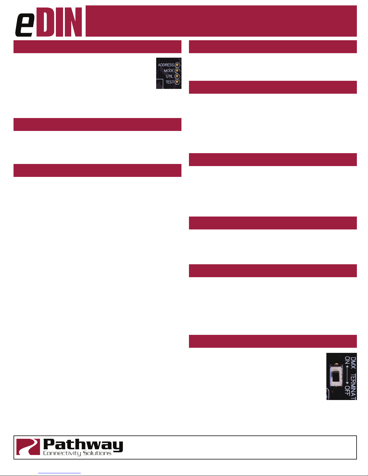
DMX rules require the last device on a DMX line to be
terminated with a 120Ω resistor between pins 2 and 3
to prevent signal reection. If there is no connection to
the DMX THRU terminals, the DMX Terminate switch
should be ON.
If there are other devices connected to the DMX
THRU terminal, the DMX Terminate switch should be
OFF and termination be applied to the nal device in the daisy-chain.
DMX TERMINATE
The 1006 is fully compliant with ANSI E1.20 Remote Device
Management as a responder device. An RDM Controller can
discover and set the card’s DMX start address, rmware version
and operating mode. The 1006 will report input DC voltages as a
sensor property.
With Pathscape software, the user can upgrade the rmware in the
eld.
E1.20 RDM RESPONDER FEATURES
Model 1006 24-Channel
Analog to DMX Manual
1006-200-REV1 04/25/19
TM
Pathway Connectivity Solutions
#103—1439 17Avenue SE Calgary AB
Canada T2G 1J9
[email protected]
www.pathwayconnect.com
tel (403) 243-8110 fax (403) 287-1281
• Power input: 9-30VDC, 5W maximum
• 250V Fault protection on DMX input
• 1500V Opto-isolation between DMX signal and analog/
contact inputs
• Connections (DMX):
• Compression Fit (Screw Terminal): stranded, 14-30 AWG
• IDC Connector: Cat5/6 or solid wire, 22-24 AWG
• Input Signal: ANSI E1.11 DMX512-A, ANSI E1.20 RDM
• Outputs: ANSI E1.11 DMX512-A
• Analog/Contact Inputs:
• Do not exceed 10VDC input when set as analog
inputs.
• Do not connect voltage sources when set as contact
inputs.
Exceeding this rating may result in personal injury
and/or equipment damage to this and other connected
devices.
• 0.7 lbs (0.316 kg)
• 6.25”W x 4”H x 1.55”D (159mm x 103mm x 40mm)
ELECTRICAL INFORMATION
PHYISCAL
• ANSI E1.11 DMX512-A(2008)/USITT DMX512(1990)
• ANSI E1.20 RDM(2010) - Remote Device Management
• ANSI E1.3 0-10V Analog Control
• RoHS 2011/65/EU
• CE
COMPLIANCE

Other pathway Recording Equipment manuals

pathway eDIN 1003 User manual

pathway

pathway eDIN 1003 User manual

pathway PWREP User manual

pathway

pathway PWREP User manual

Popular Recording Equipment manuals by other brands

Omega Engineering High Speed Load Cell Interface Card... user guide

Omega Engineering

Omega Engineering High Speed Load Cell Interface Card... user guide

Festo SPC200 Series Short description

Festo

Festo SPC200 Series Short description

Yamaha QX-5FD owner's manual

Yamaha

Yamaha QX-5FD owner's manual

Yamaha MU90R owner's manual

Yamaha

Yamaha MU90R owner's manual

TerraTec Phono PreAmp iVinyl Manual guide

TerraTec

TerraTec Phono PreAmp iVinyl Manual guide

Roland Dr. Sample SP-303 Service notes

Roland

Roland Dr. Sample SP-303 Service notes

TC-Helicon VOICELIVE Touch user manual

TC-Helicon

TC-Helicon VOICELIVE Touch user manual

Lynx greenMachine callisto quick reference

Lynx

Lynx greenMachine callisto quick reference

Hear Technologies switch back M8RX quick start guide

Hear Technologies

Hear Technologies switch back M8RX quick start guide

Roland CD-2i Brochure & specs

Roland

Roland CD-2i Brochure & specs

Viessmann 5556 Supplementary manual

Viessmann

Viessmann 5556 Supplementary manual

HHB DualBurn CDR-882 Review

HHB

HHB DualBurn CDR-882 Review

Connectivity ConnectAUDIO 2 user manual

Connectivity

Connectivity ConnectAUDIO 2 user manual

Besantek BST-CT105 instruction manual

Besantek

Besantek BST-CT105 instruction manual

r.LiNK RL4-SY3-R5 manual

r.LiNK

r.LiNK RL4-SY3-R5 manual

GRASS VALLEY T2 datasheet

GRASS VALLEY

GRASS VALLEY T2 datasheet

Meinberg microSync RX412/AD10DC20 Technical reference

Meinberg

Meinberg microSync RX412/AD10DC20 Technical reference

MOTU micro express user guide

MOTU

MOTU micro express user guide

manuals.online logo
manuals.online logoBrands
  • About & Mission
  • Contact us
  • Privacy Policy
  • Terms and Conditions

Copyright 2025 Manuals.Online. All Rights Reserved.