Medel OPUS 2 User manual

QuickGuide
OPUS Audio Processor
MAESTRO™Cochlear Implant System

2
OPUS
The World’s Smallest Audio Processor!
Features
–
an integrated state-of-the-art telecoil and
wireless access to direct-link devices, such as
FM and Bluetooth®systems
–
a new FM Battery Pack Cover with standard
input jack to provide direct connection
capabilities with electronic devices
–
the FineTuner remote control for easy
adjustments “on the fly”
–
the DaCapo Rechargeable Battery System
–
the only audio processor to include FineHearing™
with Fine Structure Processing*technology for better
music appreciation and hearing in noisy environments
–
multiple wearing styles and battery options, including
the BabyBTE,
™the world’s first processor designed
especially for young children
– the new XS battery pack makes the OPUS the
smallest audio processor available today
–
Automatic Sound Management
MED-EL’s new generation of audio
processor is a milestone achievement
in engineering. It offers unparalleled
comfort, long battery life, hands-free
capability, and remote tuning.
Using the latest advances in microchip
technology, the OPUS supports
innovative developments offering implant
users greater sound detail and clarity,
especially for music enjoyment and
difcult listening situations.
The OPUS processor is packed with
the details that let you worry less about
equipment and focus more on life.

3

4
Control Unit:
The control unit is just like a tiny computer.
Inside, an electronic chip controls the entire system. It can hold
several different programs (also called ‘maps’), which contain
the specific hearing settings for each user.
Microphone port:
This tiny opening is where sound enters
the processor. The microphone is most sensitive to sounds
coming from the front, although it is able to pick up sounds
from a wide area.
Locking earhook
(optional): The OPUS processor features
an earhook that can be secured to the control unit with a small
pin to prevent young children from removing the earhook.
LED indicator:
This small red light indicates a variety of status
and error conditions. It should illuminate when the processor is
first turned on and will indicate which position is currently active
(with , , or quick blinks). If it begins flashing during normal
use, please refer to the table on page for additional details.
Microphone cover:
This small cover is used
with the BabyBTETM and ActiveWear configurations. It
replaces the earhook for wearing options that are not
worn at the ear and serves to protect the microphone.
Integrated telecoil:
The telecoil is located in the
OPUS control unit and requires no additional parts or cables.
Select telecoil settings using the FineTuner remote control to
reduce background noise with hearing aid compatible telephones
and induction loop systems.
FM Battery Cover:
The standard input jack on the FM
Battery Cover provides the widest variety of connectivity with
different audio devices. The input jack is the same three-pin
port that is used with hearing aids – which allows new CI users
to preserve their initial investments by continuing to use their
personal assistive devices.
Control Unit
Microphone port
LED indicator
Locking earhook
On/Off switch
Battery pack
Coil
Getting to Know the OPUS
The parts and functions

5
Enlarged to show detail
DaCapo
Frame and
Battery Pack
Coil
Coil Cable
Battery Pack
On/Off Switch
Connecting Piece
Control Unit
Earhook

6
Standard Battery Pack
The Standard configuration is slim
and lightweight, with a contoured,
low-profile design that fits perfectly behind
the ear. This wearing option is ideal for
comfortable everyday use.
– Up to hours of use with a set of
three high-power zinc-air batteries
– Wireless access with integrated
telecoil and direct audio input with
FM Battery Pack Cover
DaCapo System
The DaCapo Rechargeable Battery System
contains state-of-the-art rechargeable
batteries, a battery pack and a charger.
The charger fits all international plugs
and is easy to use.
– Full day of use (up to hours)
– Wireless access with integrated
telecoil and direct audio input with
FM Battery Pack Cover
OPUS XS Battery Pack
Light and thin, the OPUS XS fits snugly
on the ear. Its Xtra Small dimensions
provide superior wearing comfort as well
as improved protection against sweat,
dirt, and dust.
– Up to hours of use with a set of
two high-power zinc-air batteries
– Wireless access with integrated telecoil
The Perfect Fit
Easy-to-Use Modular Design Provides Multiple Wearing Styles
MAESTRO is designed for your lifestyle. MED-EL pioneered
the concept of a modular system, because no two cochlear
implant users are exactly alike. Since , this modular
design has offered MED-EL users a variety of wearing
congurations to meet the needs of all ages and activities.
When implant users select the OPUS , they will have the
option to choose several wearing option choices.

Children’s Battery Pack
For small children, this configuration
is ideal because only the tiny, ultralight
control unit is worn on the ear. The
attached battery pack provides additional
security, especially during playtime.
– Up to hours of use with a set of
three high-power zinc-air batteries
– Wireless access with integrated telecoil
BabyBTE/ActiveWear
For infants & small children or individuals
participating in high-energy activities.
The entire processor, including batteries,
is attached to clothing so that it remains
securely in place.
– Up to hours of use with a set of
three high-power zinc-air batteries
– Wireless access with integrated telecoil
Mini Battery Pack
The body-worn option that is powered
by a single AAA or rechargeable
battery. It features an input jack for
easy connection to FM systems and
battery-operated audio devices.
– Full day of use (up to hours)
with DaCapo System, up to
hours with AAA battery
– Wireless access with integrated
telecoil and direct audio input
FineTuner Remote Control
The small, slim FineTuner fits easily into
your pocket if you wish to carry it with
you at all times. Changes made via the
remote control allow the user to keep
the audio processor on the ear for
uninterrupted hearing.
– Large, clearly labeled buttons make
it easy to change settings
– Controls both audio processors
independently for bilateral use
– Designed for individuals of all ages

8
Turning the audio processor ON and OFF
You may select the following positions:
. Battery pack latch open: OFF
. Battery pack latch closed: ON
Using the Safety Lock
The safety lock prevents small children from disassembling their
audio processor. After attaching the safety lock, check that the
safety lock is positioned properly. To use the safety lock:
. Insert the connecting piece with
long pins, and place the safety lock
on the protruding pins.
. The coil cable plug rests in the
cutout section.
. Slide the black lever into the shown
direction using a pointed object
(e.g. ballpoint pen) to secure the
safety lock.
. To open the safety lock, move the
black lever in the other direction.
Replacing the Coil Cable
. Open the battery pack latch and remove the
battery pack cover.
. Pull the connecting piece straight down until you feel a
slight mechanical click. The connecting piece need not be
removed completely but you may do so if you wish.
. Remove the battery pack frame from the control unit.
. Disconnect the coil cable from the control unit
and the coil.
. Connect the new coil cable to the coil.
. Insert the opposite end of the new coil cable into the
control unit. Make sure that the cable plug is correctly
positioned. The angled edge should face up, such that
the cable points diagonally upwards.
. Reconnect the battery pack frame and control unit.
The coil cable plug rests in the small cutout section
in the battery pack.
. Push the connecting piece back in place.
. Slide the battery pack cover back on and close the
battery pack latch. The audio processor is now active.
From ON to OFF,
and everything
in between
The standard battery pack includes an easy ON/OFF
mechanism and connecting piece. The battery pack
latch functions as the ON/OFF switch.
short pins
long pin
Control Unit
Coil Cable
OFF ON

9
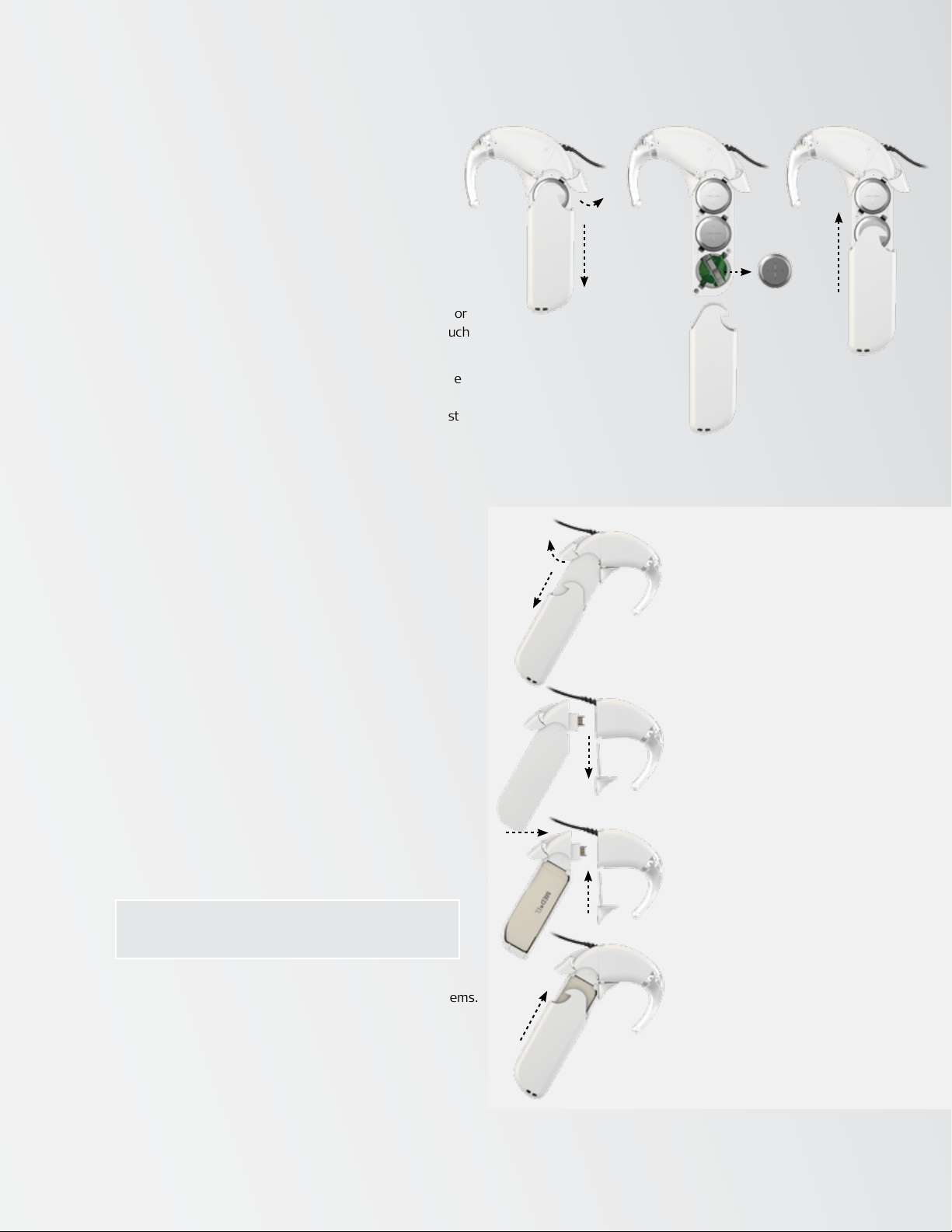
Changing the Batteries
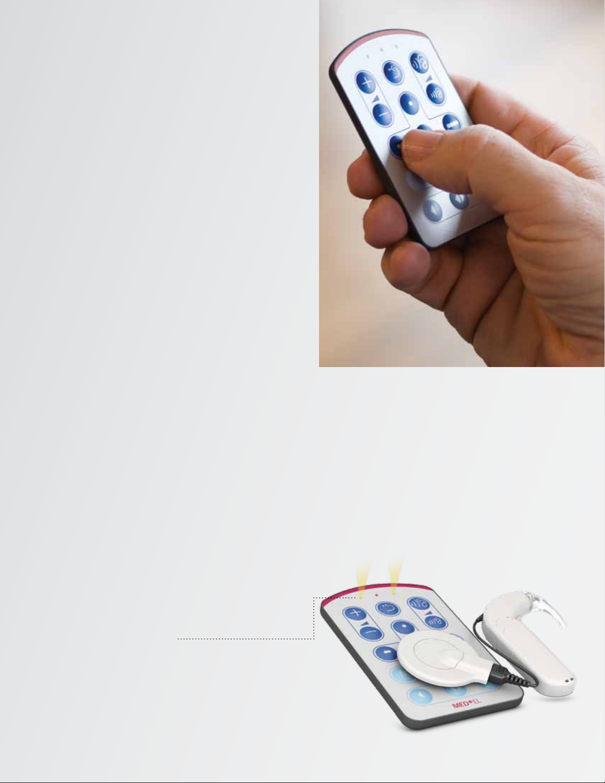
When the red indicator light blinks continuously
in a rapid pattern, the batteries should be replaced.
To change the batteries:
. Remove the coil from your head and turn off the
OPUS processor before replacing the batteries.
. Open the battery pack latch (a), and remove the
battery pack cover (b).
. Remove the three batteries (c) using the coil magnet or
by gently shaking them into your hand. Try not to touch
the battery contacts.
. The colored tab covering the zinc air batteries must be
removed before use. Check for correct polarity when
inserting the new batteries. The positive pole (+) must
face outward, i.e. the “+” sign is still visible when the
batteries are inserted.
. Slide the cover over the battery pack frame (d) and
close the battery pack latch.
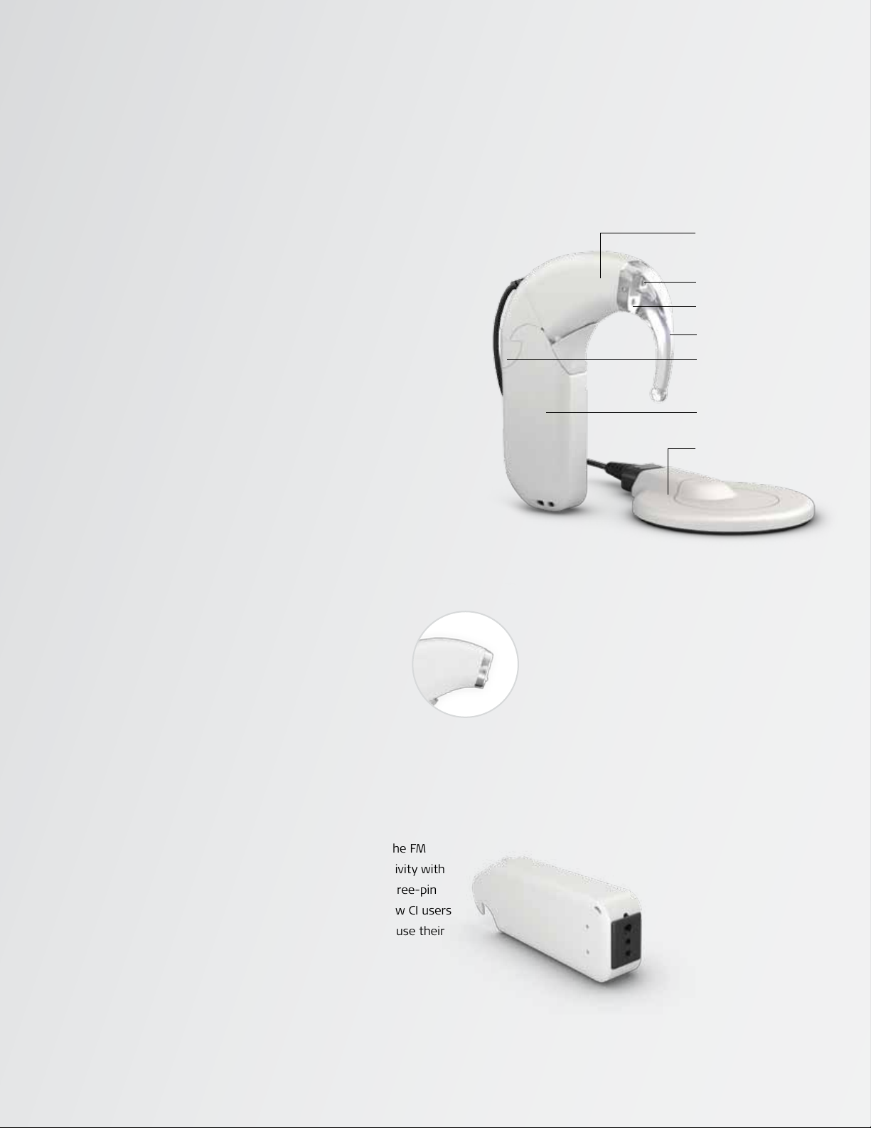
Using the DaCapo Rechargeable Battery System
The DaCapo Rechargeable Battery System is compatible
with MED-EL’s OPUS , OPUS and TEMPO+ processors.
The system consists of the DaCapo Frame and battery pack
covers, a rechargeable battery called the DaCapo PowerPack,
the DaCapo Charger, and accessories. The DaCapo Frame holds
one DaCapo PowerPack and connects to the Control Unit of
your audio processor like a standard battery pack
Features of each PowerPack include:
–
% lighter weight than using standard batteries
–
up to hours of use per charge
NOTE: when used in combination with the energy-efficient D Coil.
–
charges in under hours
–
charge/recharge cycles per battery
The battery pack lock on the DaCapo Frame
functions as the ON/OFF switch.
With the proper FM battery pack cover, the DaCapo Frame
can also support assistive listening devices such as FM systems.
To connect the DaCapo Battery Pack
to an OPUS Processor:
. Open the battery pack lock (a).
. Remove the battery pack
cover (b).
. Pull out the connecting piece (c).
. Remove the battery pack and
connect the DaCapo Frame with
PowerPack inside (d).
. Secure the DaCapo Frame to the
audio processor by inserting the
two pins of the connecting piece
into the two holes on the bottom
of the Control Unit (e).
. Slide the battery pack cover over
the DaCapo Frame and close the
battery pack lock to switch the
audio processor on (f).
NOTE: DaCapo PowerPacks can
only be used in the Standard wearing
option. The XS, Straight Battery Pack
and Children’s Battery Pack do not
offer the DaCapo option at this time.
a
b
c
f
e
d
a
bcd

10
The FineTuner remote control is an accessory device that
can be used to optimize the audio processor in changing
daily listening situations. The OPUS processor has an
ON/OFF switch. All other functions are accessed with
the FineTuner, which transmits commands to the
OPUS processor.
The FineTuner is not required for everyday use of the audio
processor. When the OPUS is turned on, it will return to
the same program, volume and sensitivity settings that were
in use when it was turned off. The FineTuner is configured
for its designated OPUS processor, so that only the target
OPUS processor can execute a command from the FineTuner.
The typical maximum operating distance between the FineTuner
and OPUS processor is approximately cm (. ft.).
This range could be decreased near electrical equipment.
How to configure the FineTuner
Once synchronized, the OPUS and Fine Tuner stay in
synchronization until one of the two pieces of equipment need
to be changed. It should only occasionally be necessary to
synchronize the FineTuner and audio processor. Examples
include use of a back-up audio processor or second FineTuner.
To configure the FineTuner:
. Turn off your OPUS processor.
. Place the coil of the OPUS processor
over the MT key on the FineTuner.
. Turn on the OPUS processor.
. The audio processor and the FineTuner will be
synchronized automatically.
. Successful synchronization is indicated by a
short blinking signal of the two amber indicator
lights on the FineTuner.
When to configure the FineTuner
For users with a cochlear implant on each ear (bilaterally
implanted), one FineTuner can be used for both ears.
However, a FineTuner can only be synchronized with one
audio processor for each ear.
The FineTuner only needs to be configured:
. At the initial audio processor fitting.
. When using a different or additional processor
(e.g., back-up, loaner or replacement, bilateral).
. When using a different FineTuner.
Using the FineTuner
The slim FineTuner™is
credit-card sized with a
thickness of only mm.

11
Navigating the FineTuner Keyboard
The FineTuner keyboard has keys.
Any of these keys can be deactivated when the audiologist
programs the OPUS processor. When a key has been
deactivated, the FineTuner will still send the command,
but the OPUS processor will ignore the command.
FineTuner Keyboard Lock feature
The FineTuner keyboard can be locked to avoid accidental
operation of a key. If the keyboard lock feature is active, the
red LED of the FineTuner will blink once every time a key is
pressed. This indicates that the command cannot be sent.
Changes to settings can still be made while the keyboard
lock is active. To activate a certain function while the
keyboard lock is active, press the desired function key twice.
The first click temporarily unlocks the keyboard, and the
second click executes the command. After seconds without
pressing another key, the keyboard lock is active again.
To disengage the automatic keyboard lock if necessary:
. Double-click the bilateral key. The first quick click of
this key will temporarily unlock the keyboard. The
second time you press this button, you should hold it
for more than seconds.
. The red and both amber indicator lights of the
FineTuner will both start blinking alternately, indicating
that you have successfully entered the FineTuner’s
program mode.
. Press the key to deactivate the keyboard
lock feature.
. The FineTuner will confirm successful deactivation
with a short blinking signal of the two amber
indicator lights.
volume setting
program selection
four settings
input selection
M: microphone only
MT: microphone with telecoil
T: telecoil only
processor selection
left, both (bilateral), right
indicator lights
one red LED for alarms
two amber LED for functions
sensitivity setting
return to default
volume and sensitivity
6.3mm thickness
Bilateral User Support
The OPUS is the FIRST processor in the
industry to offer direct support to bilateral
users. One FineTuner remote control can make
adjustments to two audio processors!
Keys on the FineTuner include:
Volume keys: Two keys to increase or decrease overall
loudness.
Sensitivity keys: Two keys to increase or decrease the
audio sensitivity.
Default key: This key sets volume and audio sensitivity
to predefined values determined by the audiologist.
Program Selection keys: Four keys to access up to four
different programs.
Input keys: Three keys to select the microphone (M),
the telecoil (T) or the microphone and telecoil together
(MT) as the signal source.
Processor keys (for bilateral users): The Processor
Selection keys allow selecting the left, right or both
processors. The keys are also used to activate or deactivate
the keyboard lock feature.

12
FineTuner Indicator Light Signals
The FineTuner has indicator lights that can provide useful
information about how the FineTuner is operating. Indicator
lights are located above the FineTuner keyboard and include
a red LED in the center with amber LEDs to the left and right.
These LEDs can provide the following information:
Changing the FineTuner battery
To conserve power, the FineTuner will only transmit a command for
a few seconds. For this reason, you should press the desired key
once for every change you wish to make. The FineTuner battery
status is checked after each transmission. When the batteries
are low, a red indicator light on the FineTuner blinks three times,
indicating that the battery should be changed. The FineTuner
battery should last for at least several months.
To change the battery:
. Open the lid on the back of the FineTuner with a
small screwdriver.
. Replace the used button battery (type CR) by removing
it with the coil magnet or by gently shaking it into your hand.
Try not to touch the battery contacts.
. Insert the new battery with the “+” sign facing up.
. Close the lid by carefully inserting it on the right side,
then sliding it in place and tightening the screw.
Insert the new battery with
the “+” sign facing up.
RED (center)
AMBER
(left side) AMBER
(right side)
FUNCTION LIGHT PATTERN MEANING
KEYBOARD
LOCKED
If you press a key while the keyboard is locked, the red
indicator light comes on.
In order to conserve power, the red indicator light will go off
after seconds even if the key is still pressed.
TRANSMITTING
INFORMATION
Left or right (or both)
lights blink according to
the side mode of the
FineTuner.
Indicator lights will blink when signals are transmitted
(the indicator light blinking corresponds to the processor being
modied - either right, left or both sides for bilateral users.)
To save energy, the FineTuner stops transmitting (and the
indicator light stops blinking) after seconds, even if the
key is still pressed.
SWITCHING SIDES
To send commands to either the left or right side, press the
corresponding button and the amber light will illuminate.
To switch both sides at once (for bilateral users) press the
button in the center. Both amber lights will illuminate.
PROGRAMMING
MODE
(+5 seconds) Press for more than seconds to enter the programming mode.
The three indicator lights will start ashing alternately.
When the red indicator light is on, the two amber indicator
lights are off and vice versa.
LOW BATTERY
blinks 3 times
If a low battery status is detected, the red indicator light
(center) will blink in a regular pattern - blinks at a time.
CONFIGURATION
SUCCESSFUL
illuminates for one second
If conguration of your FineTuner was successful, or if the
automatic keyboard lock feature was successfully activated/
deactivated, both amber indicator lights will illuminate for
approximately one second

13
Connect to the World
The OPUS features an integrated state-of-the-art telecoil and
an FM Battery Pack Cover for completely wireless access to a wide
variety of telephones, public sound systems, MP players and direct-
link systems – such as FM and Bluetooth®systems. You can access
induction loop technology at the simple touch of a button, and a
standard input jack means you can connect the same FM receivers
used with many hearing aids.
iPod is a registered trademark of Apple Computers, Inc.
registered in the U.S. and other countries.

14
Insert the telecoil
device’s 3.5 mm plug
into the headphone
jack of the music
device.
On your FineTuner,
press “MT” or “T” to
activate telecoil.
Place the telecoil
accessory around
neck (neckloop)
or on the ear
(earhook).
Using a third-party telecoil accessory:
A telecoil is a special circuit inside the audio processor
designed to pick up electromagnetic signals. These magnetic
signals – or induction signals – are wirelessly transmitted
to the audio processor by using either a neckloop, silhouette,
or induction loop system.
Aneckloop is a wire worn comfortably
around the neck that transmits signals
to the processor.
Asilhouette is an ear-level telecoil
device that is placed on the ear next
to the audio processor.
Simply plug the telecoil accessory
(neckloop or silhouette) into the audio
device or ALD receiver and select “T” or “MT” on the
FineTuner. Adjust volume as needed.
For Induction Loop Systems, simply position yourself within
the listening area and select “T” or “MT” on the FineTuner.
Adjust volume as needed.
Tip:
Electromagnetic technology is susceptible to
interference, which can cause some intermittent
humming while using a telecoil accessory.
Humming usually occurs when the user is
positioned near a source of electromagnetic
energy (power lines, fluorescent lighting,
computers, appliances, electronics, etc.).
Simply moving away from the source can remedy
interference issues if they occur.
M: Microphone T: Telecoil Only
MT: Microphone and Telecoil Together
These keys are independent of all other processor settings
and can be used with any program selection (, , or ),
volume, or sensitivity setting.
&
Plug Play
Using Telecoil
Delivering sound by magnetic induction

15
FM receivers - Many FM receivers and
direct-link devices with the standard
-pin connector (e.g., Phonak MicroLink
MLxS) can be used with the OPUS FM
battery pack cover. Turn the audio
processor off, insert the receiver, and turn
the processor back on. When the FM system is
activated, the audio processor will automatically
integrate the sound signal.
Audio Cables - Connect the -pin connector
of the MED-EL Audio Cable (gray end) to the
openings at the bottom of the FM battery pack
cover. Mind the orientation of the three pins
and do not use excessive force when connecting
the cable. Connect the audio plug (yellow
or red end) to the audio output
of the battery-powered device.
Replace the
Standard Battery
Cover with the
FM Battery Cover.
Replace the
Standard Battery
Cover with the
FM Battery Cover.
Insert the audio
cable’s 3-pin plug
into the FM Battery
Cover port.
Carefully insert
the mini-receiver
into the port at
the bottom.
Insert the audio
cable’s 3.5 mm plug
into the headphone
jack of the music
device.
Refer to the FM
system user manual
for options to
adjust FM setting
if necessary.
Using MED-EL’s direct-connect audio cable:
Using third-party FM receivers:
&
Plug Play
Tip:
Direct connections almost always provide a
distortion-free, clear listening experience not
limited by interference issues that telecoil
accessories may sometimes encounter. However,
FM systems themselves may be susceptible to
interference from the FM signal.
Audio cables running from the processor can be
somewhat restrictive since this is not a wireless
option. Extensive use of audio cables can also
slightly decrease processor battery life.
Direct Audio Input
With the FM Battery Pack Cover

r.
MED-EL Medical Electronics
Headquarters
Fürstenweg a
Innsbruck, Austria
office@medel.com
MED-EL Corporation, USA
Old Cornwallis Road, Suite
Durham, NC , USA
Tel.: --
Fax: --
Toll Free: () MED-EL-CI (-)
implants-usa@medel.com
www.medel.com
Join us on Facebook
facebook.com/medel.hearlife
Follow us on Twitter
twitter.com/medel
Watch us on YouTube
youtube.com/MEDELnetwork
Other manuals for OPUS 2
1
Table of contents
Other Medel Recording Equipment manuals