2.2 STANDARD FEATURES
Code Description
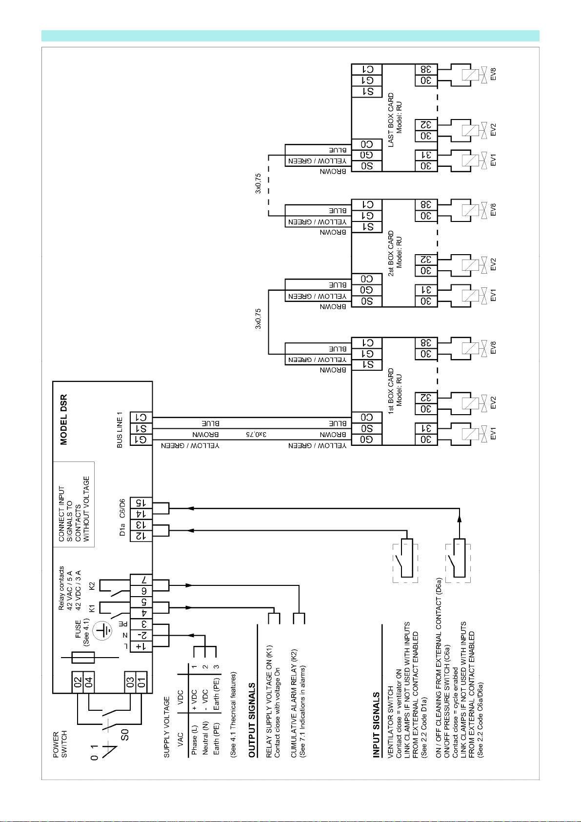
A2a Relay Voltage ON (K1)
If the device is supplied, relay K1 is activated and the terminal board contact is closed. In case of power failure, this
contact is open.
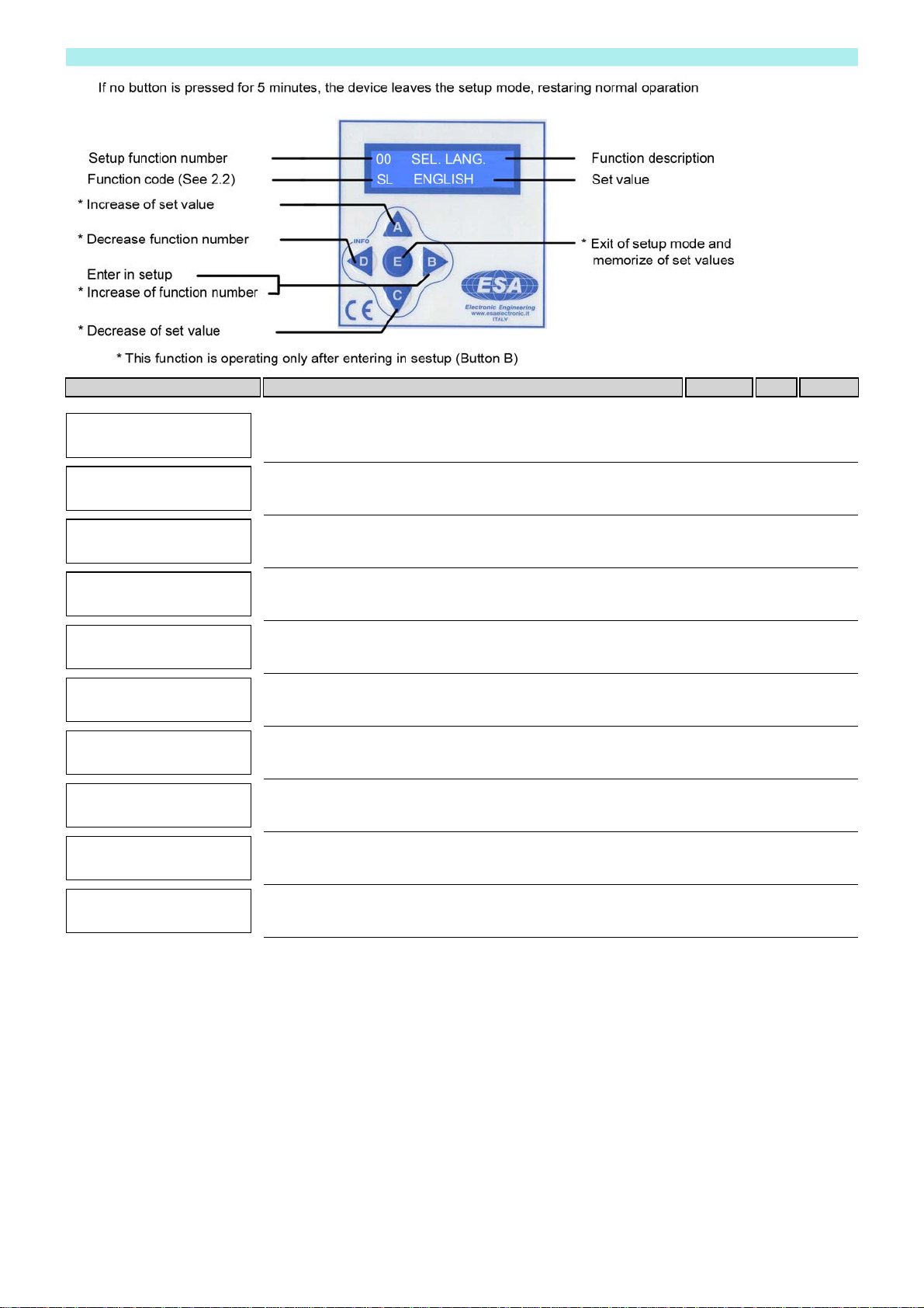
B10b Manual activation of every single output from keyboard
By keyboard, it is possible to activate manually and individually every single output for an operation test.
Press key C to select the desired output to be activated. Press key A to activate the output.
The output is holded active for all the time that key A is pressed. It allows to measure the output voltage by using a
tester.
In case of anomalous operating, do this test with electrovalves disconnected.
B1b Select Number of outputs
The selection of the number of outputs to be control led is connected by keyboard in SET MODE. If you set 0 or AUTO
in this function the sequencer will automatically select the connected loads by skipping the non connected ones.
Minimum load 5W ÷ 12 W depending on the output voltage. If the load is below of the minimum, the autoselection does
not work correctly, set the number of outputs in set up.
B2x Activation time from 0.05 to 5.00 sec.
B3x Interval time from 1 to 999 sec.
If the pulse time is lower than 1 sec. it is possible to set any interval time value in the range indicated.
If the activation time is higher than 1 sec. the minimum settable interval time is:
Minumum interval time = 5 times pulse time (B2x)
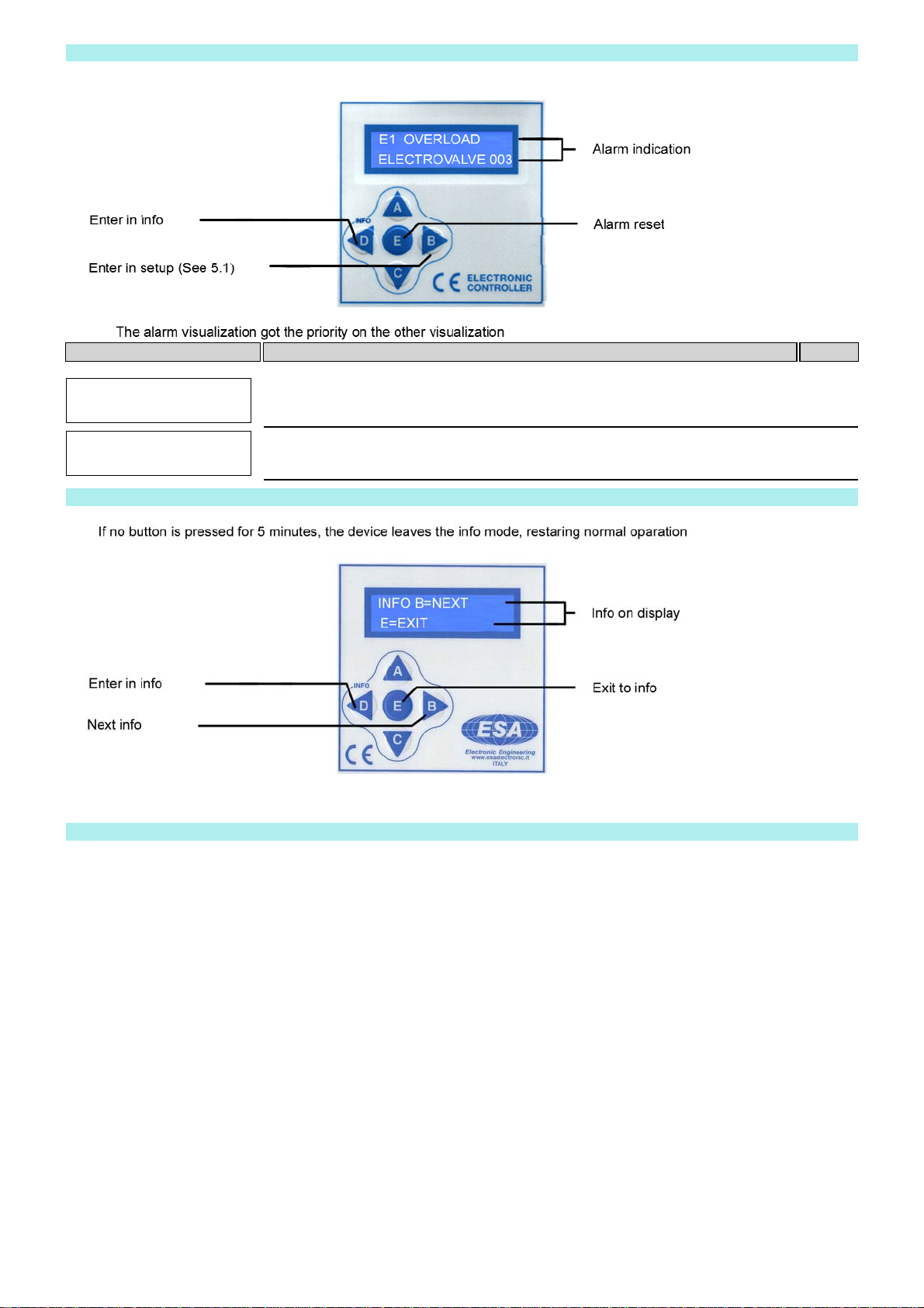
B8a Short-circuit protection of every single output
In case of short circuit, the output is automatically skipped, the relay K1, normally active, is deactivated and the terminal
board contact opens.
The display alternatively shows code E1 and the number of the faulty output.
Press key B to reset the alarm.
B9b Electric control of output activation
If a solenoid valve is not activated, the relay K2 indicate the alarm condition and the display shows the alarm condition
code E2 (See alarm description).
Press key 'E' to reset alarm condition.
ATTENTION: this function will be active only if the automatic selection of the load in set up is not selected.
The alarm switch on after 5 consecutive fails on the same output.
C0 Input activation from external contacts
In Set up you can activate or deactivate the control of all the inputs of the device.
If inputs are deactivated, they are considered as always closed and no jumper is required on the terminal board.
Use a jumper for unused inputs if you activate them.
NOTE: all inputs of the device have to be connected to external contact without voltage.
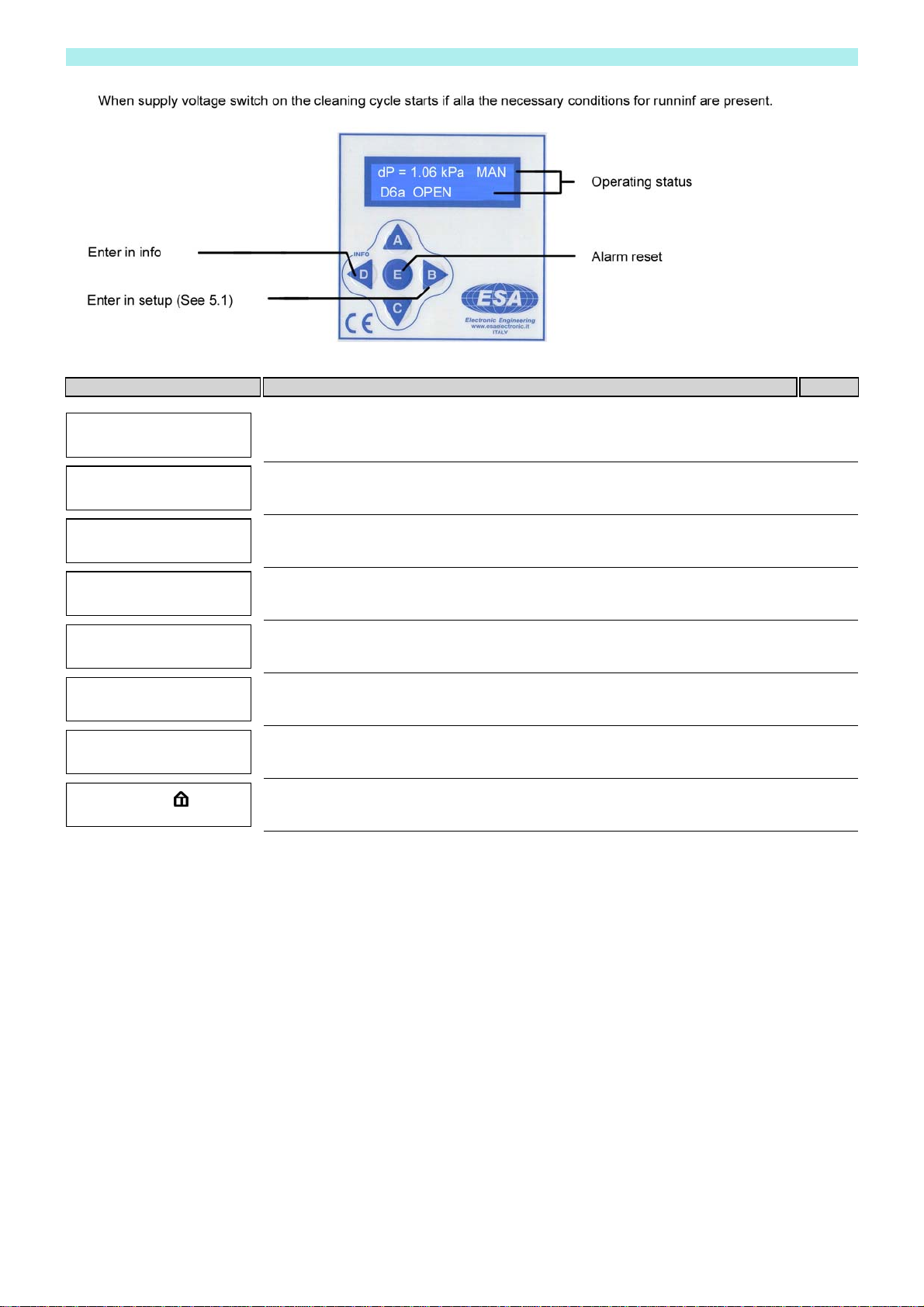
C4c Cleaning cycle
If all the conditions necessary for the start of cleaning cycle (e.g. fan On, external consents C6 or D6 present) are
present when supply voltage is switched on, automatically the device activates the outputs in sequencial way with
timing set by keyboard
C6a ON/OFF cleaning cycle from external pressure switch. STOP at the end of the cycle
With digital inputs enabled and with contact C6a open the cleaning cycle stops at the end of the cleaning cycle and
display shows 'CYCLE STOPS FOR LOW dP'.
When C6a is closed the cleaning cycle restart.
NOTE. Put a wire between the clamps of input C6a if not used with inputs enabled.
D14a Operation hours-counter
In Setup it is possible to visualize an hours counter. This counter is active when the cleaning cycle in On. In case of fan
stop, consent D6 not present or with the device in Setup the counter stops.
D1a3 Additional cycles from voltfree contact. ALWAYS enabled.
By connecting an NO auxiliary contact of the circuit intended to drive the fan with the sequencer, it is possible to add a
pre-set number of cleaning cycles after the fan stop. Their number can be set from 0 to 99 by keyboard.
Post-cleaning cycles are activated even if dP = 0 or C6x open.
If contact D1a3 is open, the display shows the indication of fan stop (See operation table 6.1).
The display shows 'POST-CLEANING ACT' or decimal points blink, according to the model, during additional cycles.
NOTE. Jump D1a3 clamps if it is not used with inputs enabled.