Patio Glow WT17IL User manual

1
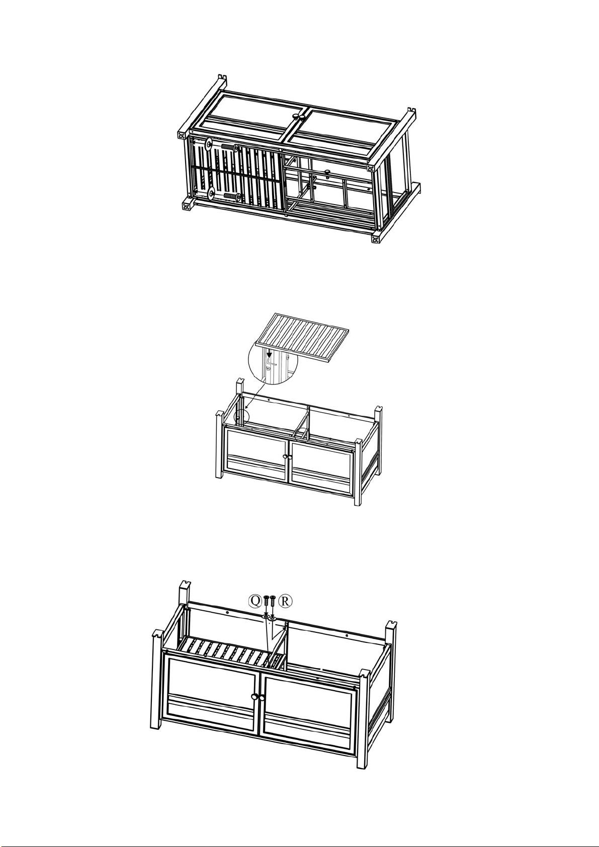
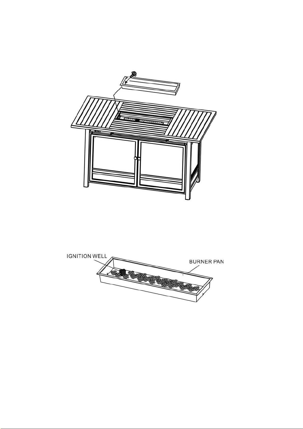
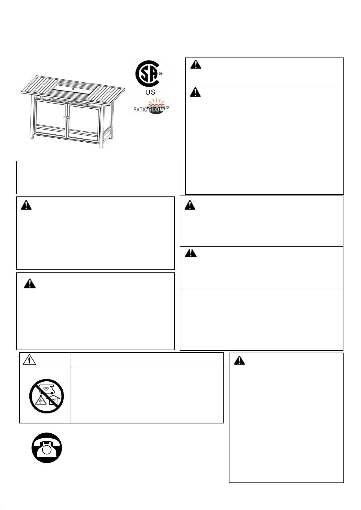
ASSEMBLY INSTRUCTIONS
WARNING:
USE FACTORY APPROVED
REPLACEMENT PARTS AND
ACCESSORIES ONLY. USE OF
UNAPPROVED PARTS OR
ACCESSORIES CAN VOID
THE WARRANTY ON THIS
PRODUCT AND RESULT IN A
HAZARDOUS CONDITION.
PLEASE CONTACT US FOR
INFORMATION REGARDING
REPLACEMENT HOSES,
THERMOCOUPLES,
ELECTRODES, IGNITION
MODULES, LAVA ROCKS,
LOGS, FIRE ICE, ETC.
If you have any problems with this product (missing or
damaged parts, assembly issues, etc.), please do not
return to the retailer/store from where you purchased the
product. Please send e-mail to customer service
account : customer-service@dali-vip.com.cn
Thi
s app
li
ance can pro
d
uce car
b
on
monoxide which has no odor.
Using it in an enclosed space can kill
you.
Never use this appliance in an enclosed
space such as a camper, tent, car or
home.
DANGER CARBON MONOXIDE HAZARD
CSA Model
WT17IL
ARW09500
DANGER
If you smell gas:
FIRE OR EXPLOSION HAZARD
If you smell gas:
•shut off gas to the appliance.
•Extinguish any open flame.
•if odor continues, leave the area
immediately.
•After leaving the area, call your gas
supplier or fire department.
Failure to follow these instructions could
result in fire or explosion, which could
cause property damage, personal injury, or
death.
WARNING:
If the information in this manual is not
followed exactly, a fire or explosion may
result causing property damage, personal
in
j
ur
y,
or loss of life.
WARNING:For Outdoor Use Only.
Installation and service must be performed
by a qualified installer, service agency, or
the
g
as su
pp
lier.
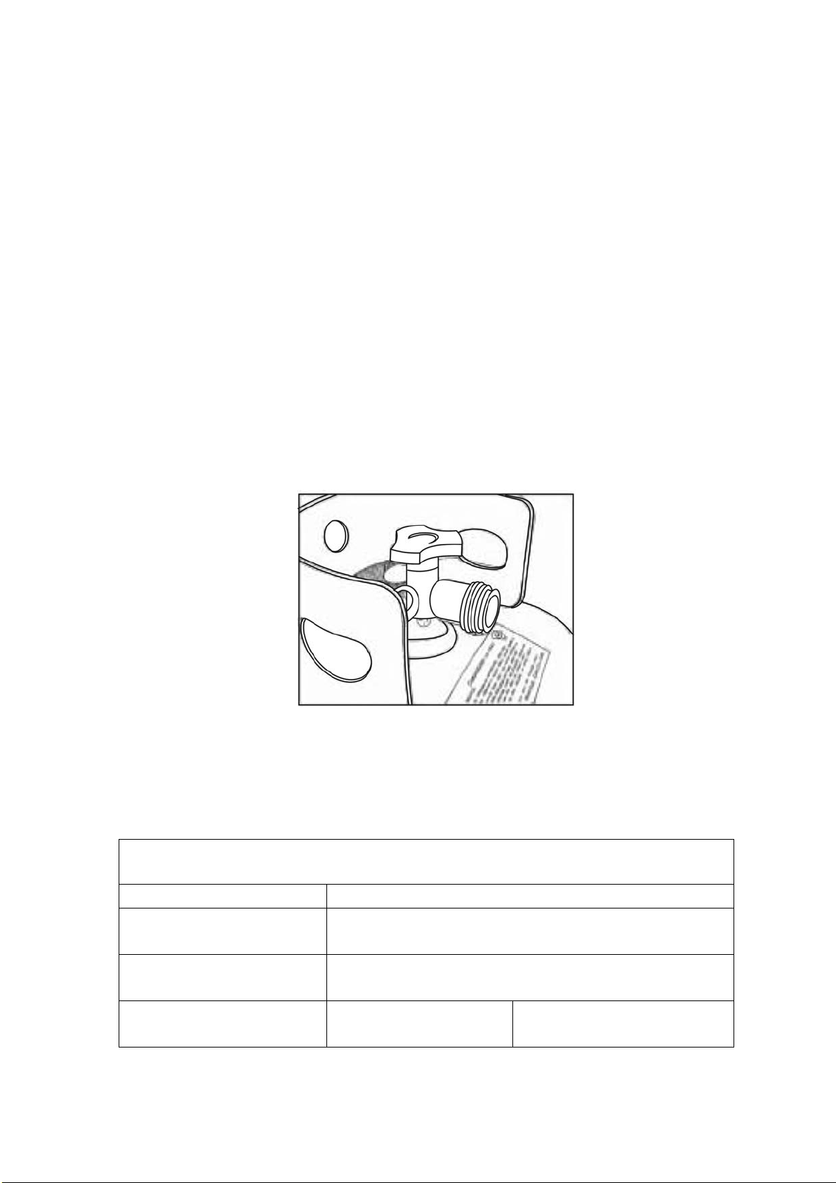
FOR USE WITH 9KG (20LB) PROPANE
CYLINDER(NOT INCLUDED) WITH TYPE 1
CONNECTION OR FOR USE WITH NATURAL
GAS AFTER CONVERSION KIT IS
INSTALLED (MUST BE PROFESSIONALLY
INSTALLED).
Installer: Leave these instructions with consumer.
Consumer: Keep these instructions for future
reference.
WARNING:
Improper installation, adjustment
alteration, service, or maintenance can
cause injury or property damage. Read the
installation, operating, and maintenance
instructions thoroughly before installing or
servicing this equipment.
WARNING
Do not store or use gasoline or other
flammable vapors and liquids in the
vicinity of this or any other appliance.
An LP-cylinder not connected for use shall
not be stored in the vicinity of this or any
other appliance.
WARNING:
It is UNSAFE to use this product for cooking!

2
TABLE OF CONTENTS
Important Safety Information .................................................................3
Important Information about Propane....................................................4
Specification ..........................................................................................4
Parts Identification List ...................................................................... 5-6
Installation ....................................................................................... 7-11
Natural Gas Conversion ................................................................ 12-13
Maintenance........................................................................................13
Batteries ..............................................................................................14
Lighting Instructions ............................................................................14
Troubleshooting Guide ........................................................................15
Warranty..............................................................................................16

3
IMPORTANT SAFETY INFORMATION
The installation must conform with local codes or, in the absence of local codes, with the National Fuel Gas
Code, ANSI Z223.1/NFPA 54; International Fuel Gas Code. ; Natural Gas and Propane Installation Code, CSA
B149.1; or Propane Storage and Handling Code, B149.2, as applicable.
The appliance and its appliance main gas valve must be disconnected from the gas supply piping system
during any pressure testing of that system at test pressures in excess of 1/2 psi (3.5kPa).
The appliance must be isolated from the gas supply piping system by closing its equipment shutoff valve during
any pressure testing of the gas supply system at test pressure equal to or less than 1/2 psi (3.5kPa).
The appliance area must be kept clear and free from combustible materials, gasoline and other flammable
vapors and liquids.
Do not use this appliance if any part has been under water. Immediately call a qualified service technician to
inspect the appliance and to replace any part of the control system and any gas control which has been under
water.
Children and adults should be alerted to the hazards of high surface temperatures and kept at a safe
distance to avoid burns or clothing ignition.
Young children should be carefully supervised when they are anywhere near the appliance.
Clothing or other flammable material should not be hung from the appliance, or placed on or near the
appliance.
Any screen or guard removed for servicing an appliance must be replaced prior to operating the
appliance.
Installation and repair should be done by a qualified service person. The appliance should be inspected
before use and at least annually by a professional service person. More frequent cleaning may be
required as necessary. It is imperative that the control compartments, burners and circulating air
passageways of the appliance be kept clean.
Do NOT burn solid fuels in this gas fireplace.
Do NOT ignite the burner before pouring all of the burner media (lava rock or fire ice) into the burner pan. The
media must be evenly distributed over the burner.
During initial firing of firepit, please stay away from the firepit for 20 minutes as fire media (lava rock or fire ice)
may pop and hit someone on the face or eyes
Do NOT ignite or use the firepit if the burner media (lava rock or fire ice) are wet. Ensure the burner media are
completely dry before igniting as intense heat could cause the media to crack and pop.
It is UNSAFE to use this product for cooking!
CAUTION: The propane gas pressure regulator provided with this appliance must be used. This regulator
is set for an outlet pressure of 11 inches water column.
This outdoor gas appliance is not intended to be installed in or on recreational vehicles and/or boats.
Before each use of this gas appliance, open the LP (Liquid Propane) Tank Drawer and inspect the LP Hose. If
there is evidence of excessive abrasion or wear, or the hose is cut, it must be replaced prior to the gas
appliance being put into operation. Use only the replacement hose assembly specified in this manual. Inspect
the burner before each use of the appliance. The burner must be replaced prior to the appliance being put into
operation if it is evident that the burner is damaged. Use only the burner listed in these instructions.
Keep the fuel supply hose away from any heated surfaces.

4
IMPORTANT SAFETY INFORMATION ABOUT
PROPANE (LP) GAS
A LP-gas cylinder for use with this appliance must have a capacity of 20 lbs / 9kg.
and must be equipped with a Type 1 connector and an OPD (overfill protection
device). Figure 1
The LP-gas supply cylinder to be used must be constructed and marked in
accordance with the specification for LP-gas cylinders of the U.S. Department of
Transportation (DOT) or the National Standard of Canada, CAN/CSA-B339,
Cylinder, Sphere and Tubes for the Transportation of Dangerous Goods.
The cylinder supply system must be arranged for vapor withdrawal.
The cylinder used must include a collar to protect the cylinder valve.
This appliance shall be used only outdoors in a well-ventilated space and shall
not be used in a building, garage, or any other enclosed space.
When this appliance is not in use, the gas must be turned off at the supply
cylinder.
Storage of this appliance indoors is permissible only if the cylinder is
disconnected and removed from the appliance.
Cylinders must be stored outdoors in a well-ventilated area out of the reach of
children. Disconnected cylinders must have threaded valve plugs tightly
installed and must not be stored in a building, garage, or any other enclosed
areas.
Figure 1
SPECIFICATIONS
The maximum inlet supply pressure, as follows:
“Max. gas supply:6922 in wc (1723Kpa)”
INPUT 30,000 Btu/hr(8.8kW)
Propane Regulator
Pressure
11 in / 2.74 kPa water column
Natural Gas Minimum
Inlet Pressure
7 in / 1.74 kPa water column
Clearances to
combustible surfaces
Sides 24 in / 60.96
cm
Top: 72 in / 182.88 cm

5
PART DESCRIPTION PART# QTY
A CONTROL KNOB 1
B GAS VALVE 1
C THERMOCOUPLE 1
D FLEX CONNECTOR 1
E ELECTRODE 1
F IGNITION MODULE 1
G LP REGULATOR HOSE ZCF0161 1
H LP TANK RETAINING KNOB 2
I ADJUSTABLE FOOT CAPS 31-PC-0835 4
J PROPANE ORIFICE ZCF0169 1
K NATURAL GAS ORIFICE ZCF0170 1
L FIRE ICE(TOTAL:7KG) ZCF0224 1
M AIR SHUTTER SF00F6142 1
N “AA” BATTERY(1.5V) ZCF0148 1
O M4 SCREW 2
P 1/4” X20 MM BOLT SC111X020 8
Q 1/4” X30 MM BOLT SC111X030 9
R 1/4” X35 MM BOLT SC111X035 1
S Ø6.5 X 1.0 MM WASHER SF00F1991 14
T
Ø20 X Ø6.5 X 2.0 MM
WASHER SF00F2099 4
PARTS IDENTIFICATION LIST

6
U HEX BOLT DRIVER SE00F1994 1
V
CROSS POINT
SCREWDRIVER SE00F6204 1
W
BURNER PAN PROTECTIVE
RING 1
X
FIREPAN/BURNER
ASSEMBLY 1
Y
BURNER COVER 1
Z FIREPIT TABLETOP 1
AA
MIDDLE PANEL 1
BB
BOTTOM PANEL 1
CC
BACK PANEL 1
DD
DOOR PANEL 1
EE SUPPORT BAR-1 1
FF SUPPORT BAR-2 1
GG ORIFICE HOLDER 1

7
INSTALLATION
1. Identify the parts packed in the carton against the parts list. Remove all protective
materials and set parts on a flat, non-abrasive surface.
IMPORTANT NOTE: WE RECOMMEND TWO PEOPLE WORK TOGETHER TO
ASSEMBLE THE PRODUCT.
2. Place the back panel upside down on a flat, non-abrasive surface. Open it as shown in
Figure 2.
Figure 2
3. Assemble the door panel to the back panel as shown in Figure 3.
Figure 3
4. Attach the bottom panel to the legs by using four 1/4"x30 mm bolts and Ø6.5x1.0mm
washers as shown in Figure 4. Guide the bolts through holes in the bottom panel, into
pre-drilled holes in the legs. Hand tighten only.

8
Figure 4
5. Carefully place the middle panel inside back panel with bottom panel as shown in
Figure 5.
Figure 5
6. Attach the bottom panel to the back panel by using a 1/4"x30 mm bolt, a 1/4"x35 mm bolt
and two Ø6.5x1.0mm washers as shown in Figure 6. Guide the bolts through holes in the
bottom panel, into pre-drilled holes in the back panel. Hand tighten only.
Figure 6

9
7. Attach the support bars to the firepan/burner assembly by using four 1/4"x30 mm bolts
and Ø6.5x1.0 mm washers as shown in Figure 7. Hand tighten only.
Figure 7
8. Attach the complete firepan/burner assembly to back panel with door panel by using four
1/4"x20 mm bolts and Ø6.5x1.0 mm washers as shown in Figure 8. Hand tighten only.
Figure 8
9. After making any necessary adjustments to the alignment of the all parts, use the hex bolt
driver to tighten all bolts. Do not over tighten. Over tightening may strip bolts.
10. Place the firepit tabletop onto the firepit base. Secure the tabletop to the firepit base by
using four 1/4"x20 mm bolts and Ø20xØ6.5x2.0 mm washers that are provided. See Figure9.
Figure9

10
11. Place the burner pan protective ring into the firepan/burner assembly as shown in Figure 4.
Align the holes in the burner pan protective ring with the pre-drilled holes on the firepan/burner
assembly. Secure the burner pan protective ring to the firepan/burner assembly by using the
two M4 screws as shown in Figure 10.
Figure10
12. Pour ALL of the provided media (fire ice or lava rock) into the burner pan. The burner
MUST be completely covered to ensure the appliance functions properly and safely. Remove
any lava rocks or fire ice on top of the ignition well. See Figure 11.
Figure 11

11
13. Open the tank door, place the tank in the holder and connect the regulator as shown in
Figure 12. Turn the black handle clockwise to tighten. Turn the handle counterclockwise to
remove. The hose must point down. Open the control door and check that the valve is
turned all the way clockwise to the “OFF” position. Open the tank valve. Apply a solution of
soapy water to the tank-regulator connection and to the valve-hose connection to check for
leaks. If soap bubbles continue to form, the connection has a leak. If a leak is found, close
the tank valve and tighten all connections. NEVER USE A FLAME TO CHECK FOR
LEAKS.
Figure 12
14. Tighten threaded knobs (H) found on the tank tray (Figure.13) so that the LP tank cannot
move from side to side. Do not remove the plastic cap from the end of the threaded section.
Figure 13

12
NATURAL GAS CONVERSION
Natural gas conversion must be performed only by your natural gas provider or service
company.
1. SHUT OFF THE GAS SUPPLY TO THE UNIT AND ANY NEARBY ELECTRICAL SOURCE
OR APPLICANCES
2. Below the burner, carefully disconnect flex connector attached to the orifice holder (see step1).
3. Carefully unscrew the orifice holder from the burner pipe (see step2).
4. Remove the propane orifice from the holder and replace with natural gas orifice (see step2).
5. Install the air shutter over the burner pipe to cover the air holes. Then reattach the orifice
holder to the burner pipe (see step3).
6. Reattach the flex connector to the orifice holder. (see step 4).
7. To convert the regulator from propane to natural gas, the appliance must be isolated from the
gas supply piping system by closing its individual manual shut off valve. Ensure any pressure
testing of the gas supply piping system is at test pressure equal to or less than 1/2 psi(3.5KPA)
8. Remove the propane rubber hose from valve and replace with 5/8” natural gas pipe (see step5,
natural gas pipe package is not provided).
9. Restore your gas supply and check ALL of the connections for leaks using a solution of soapy
water. If a leak is discovered and any bubbles are seen, close the main gas valve and re-tighten
Flex
connector
Orifice
holder
Propane
orifice
(1.67mm)
Air
shutter
NaturalGas
orifice
(2.44mm)
Step1 Step2
Step3 Step4

13
ALL the connections. NEVER USE A FLAME TO CHECK FOR GAS LEAKS!
Step5
10. Stick the conversion label on the rating plate as shown in Figure 14.
Metal Rating Plate
Conversion Label
MAINTENANCE
The flames should look like those in Figure 15. To clean
the burner, use a soft brush after the burner has cooled
completely. Never use a vacuum cleaner on the burner.
It is recommended to store the fire pit indoors during
winter if it will be subjected to freezing temperatures. The
LP cylinder must be disconnected and removed from the
appliance before the appliance can be stored indoors.
Figure15
SerialNumber :ModelNumber : WT17IL
Numérodesérie Numérodemodèle
For Outdoor Use Only. If Stored Indoors, Detach and Leave Cylinder Outdoors.
The gas supply must be turned off at the propane gas supply cylinder when this appliance is not in use
Figure 14

14
BATTERIES
Make sure the control knob is in the "OFF" position. Unscrew the push
button cap on the ignition module located on the control panel to
access the battery compartment. The ignition module requires one
Alkaline AA size battery (1.5V) (Included). The negative (-) end goes
in first. See Figure 16. Dispose of the battery safely as it may explode
or leak if charged or disposed of in fire. Make sure of the polarity.
Mercury and cadmium free.
Figure 16
CAUTIONS: BATTERY INSTRUCTIONS
●Always purchase the correct size and grade of battery most suitable for the intended use.
●Always replace the whole set of batteries at one time, taking care not to mix old and new ones, or batteries of different types.
●Clean the battery contacts and also those of the device prior to battery installation.
●Ensure the batteries are installed correctly with regard to polarity (+ and -).
●Remove batteries from equipment which is not to be used for an extended period of time.
●Remove used batteries promptly.
For recycling and disposal of batteries to protect the environment, please check the internet or your local phone directory for
local recycling centers and / or follow local government regulations.
LIGHTING INSTRUCTIONS
Warning: If these instructions are not followed exactly, a fire or explosion may result causing
property damage, personal injury, or loss of life.
1. Read instructions before lighting.
2. Push and turn the knob to ON.
3. Hold ignitor to light the burner, release control knob after 15 seconds; if burner does not
light , wait 5 minutes ,repeat.
4. Adjust flame to desired flame with the control knob. See Figure 17.
IGNITER BUTTON CONTROL KNOBFigure 17

15
TROUBLESHOOTINGGUIDE
PROBLEM CAUSE REMEDY
Burner won’t light
No propane gas at burner
Check that the gas tank valve is
open. Turn the control knob to “ON”
and push the control knob in. Make
sure the tank has propane gas.
No spark at electrode
Check that the AA battery is installed
with the negative (-) end first and has
a charge. Check that the wire is
connected to the ignition module.
Check that the electrode is not
cracked or broken.
Lack of oxygen Remove excess fire ice from around
the ignition well.
Burner won’t stay
lit after lighting
Thermocouple not in flame
Check that the tip of the
thermocouple is even with the top of
the ignition well. Remove any fire ice
from the ignition well.
Thermocouple connection
at the main control valve is
loose
Tighten the thermocouple nut at the
back of the valve.
No fire ice on burner Cover the burner with fire ice per the
instructions.

16
ONE-YEAR LIMITED WARRANTY
What is Covered Under This Warranty?
The item you have purchased is warranted against defects in material and workmanship for
the following parts from the date of purchase for the period of warranty as outlined below,
but only when the unit is installed and operated in accordance with the instructions in this
Owner’s Manual and in compliance with local building and fire codes:
Limited 1 Year
•Stainless Tube/Plate burner
Limited 90 days
•All remaining parts
How Do I Obtain Warranty Service?
To obtain warranty service, you must contact our customer service center within the relevant
warranty period and provide us with a copy of your dated register receipt as proof of the
purchase date. We reserve the right to request photographs and/or return of the defective
item(s) and/or such other evidence relating to any claim as we shall reasonably require.
please call your local Casual Classics Dealer.
What are the Limitations and Exclusions of this Warranty?
Warranty Limitations:
This warranty is subject to the limitation set forth above. In addition, this warranty is made to
the original purchaser only and is effective only if items are purchased from one of our
authorized dealers. This warranty is not transferable. For warranty replacements based on
warranty claims, we will not be responsible for charges associated with shipments outside
continental North America at any time or for any reason.
Warranty Exclusions: This warranty is subject to the exclusions set forth above. In addition,
the following are excluded from coverage under this warranty: any item used for commercial,
contract or any other non-residential purpose; clearance items, display models or items
purchased “as is”; freight damage; items subject to misuse, abuse, neglect or lack of proper
care or maintenance (including without limitation as provided in any “care and maintenance
guide” or similar information we provide); normal wear and tear; damage caused by acts of
nature, acts of force majeure, vandalism, fire or other casualty, or improper assembly;
hardware against corrosion or rusting; purchased or replacement parts; and all plastic parts.
Also excluded are loss of use or time; inconvenience; money; travel; packaging; or
incidental, special or consequential damages of any kind. Replacement of defective items or
parts as provided herein, or (at our sole discretion) pro rated refund of your purchase price,
shall constitute your sole and exclusive remedy for items which are not as warranted. In no
event shall our responsibility exceed the purchase price of the item found to be other than as
warranted. This warranty is the exclusive statement of your rights with respect to items you
have purchased and supersedes any other express warranty or statement, written or oral,
made in connection with the purchase and sale of such items. The term ”item” when used
herein in the singular refers to the specific piece found to be defective, and not to the entire
set of which the item is a part.
Some states do not allow exclusion or limitation of incidental or consequential damage, so
that limitation may not apply to you. This warranty gives you specific legal rights, and you
may also have other rights that vary from state to state.
This manual suits for next models
1
Table of contents
Other Patio Glow Outdoor Fireplace manuals
Popular Outdoor Fireplace manuals by other brands

Canvas
Canvas LFT1224PST-A Assembly instructions

Majestic
Majestic Vermont Castings ODSHR42 Homeowner's installation & operating manual

HPC
HPC Electronic Ignition Flame Control System Safety manual

Courtyard
Courtyard PASADENA owner's manual

California Outdoor Concepts
California Outdoor Concepts OUTDOOR LIVING REDEFINED OUTDOOR FIREPIT owner's manual

Coleman
Coleman Firelight 5071 Series Instructions for use