Patlite LA6 series User manual

B95100496_01
Signal Tower
Complete Operation Manual
[Type: LA6]

2
Table of Contents
1. Introduction 3
1.1. Safety Precautions 3
1.2. For safe application, observe the following: 3
1.3. About this Product 4
2. Model Number Conguration 5
3. Part Names and Dimensions 6
3.1. Outer Appearance List 6
3.2. Part Names and Outer Appearance 7
3.3. Attachment Angle Part Names and Dimensions 9
4. Mounting Direction 10
5. Wiring 13
5.1. Wiring Examples 14
5.1.1. Connecting to Relay Contacts [DC24V Type] 15
5.1.2. Connecting to a PLC (NPN) [DC 24V Type] 15
5.1.3. Connecting to a PLC (PNP) [DC 24V Type] 16
5.1.4. Connecting to Relay Contacts [AC 100 -240V Type] 17
5.1.5. Connecting to a PLC (NPN) [AC 100 -240V Type] 17
5.2. Current Capacity 18
5.2.1. Contact Capacity [DC 24V Type] 18
5.2.2. Contact Capacity [ AC 100 - 240V Type] 18
6. Operating Directions 19
6.1. “Signal Tower” mode 19
6.2. “Smart Mode” 20
6.2.1. “Time-trigger”mode 20
6.2.2. “Pulse-trigger” mode 22
6.2.3. “Single-display”mode 24
6.3. Multi-function Button Operation 26
6.4. Factory Default Data 30
7. Changing Data 37
8. Time Chart 38
8.1. Basic Signal Input Time Chart 38
8.2. Trigger Input Signal Time Chart 38
9. Before Requesting Repair 39
10. Replacement Parts 40
11. Specications 41

3
LA6 Signal Tower Complete Operation Manual
1. Introduction
Thank you very much for purchasing our PATLITE product. Please read this comprehensive operation manual
thoroughly before use. In addition, please store this manual for future reference when performing maintenance,
repairs or inspections. When performing maintenance and repairs, etc., please be sure to reread this book.
If there are any questions concerning this product, please refer to the information on the last page to ask your
nearest PATLITE Sales Representative.
1.1. Safety Precautions
The following symbols classies the following precautions into two catagories and explains the level of harm inicted when
caution is disregarded while using this product.
Contrary to Warnings and Cautions indicated in this document, product failure due to mishandling, disassembly, modications
or natural disasters, etc. is not covered by any Warranty. Moreover, avoid any applications outside those indicated in this
document.
1.2. For safe application, observe the following:
WARNING
Indicates an imminently dangerous condition: Failure to follow the instructions may lead to
death or serious injury.
CAUTION
Indicates a potentially dangerous condition: Failure to follow the instructions may lead to slight
injury or property damage.
Please Indicates something to observe before using this product. The disregard to this indication may
lead to product malfunction or failure.
Note Indicates a notice regarding supplementary information or convenient explanation of this
product.
WARNING
• Prior to installation and wiring, ensure the power is disconnected and the Main Unit is turned o. Failure to comply may
result in electric shock.
• Be sure the wiring is correct. If an error is made in wiring, the internal circuit will be damaged and may cause a re.
• Be sure the power source is in the voltage tolerance when using it. Failure to comply may result in malfunction or re.
• Do not modify or disassemble the product. Possibility of re or electric shock may occur. Refer to the“Troubleshooting”
section, or ask for technical consultation from the addresses indicated in this manual for repair, etc. of this product.
• Be sure to request the installation and wiring be performed by a professional contractor. There is a risk of an electric shock,
re, or falling.
• When the product is mounted onto equipment, do not use it as leverage to climb onto the equipment, etc. Failure to
comply will result in falling from a high place, or damage to the product.
CAUTION
• Avoid long exposure to the alarm sound from a close distance. Failure to observe this may lead from irritation to permanent
damage to the ears.
• Do not install the product in a location where vibrations exceeding the specications exist. Failure to comply may result in
the prevention of the product detaching and falling, causing injury to a passer-by, etc.
• Do not remove parts beyond those designed to be removed from this product. Failure to comply will result in damage to
the product.
[ B Flashing/Alarm Type]
• By all means, do not apply voltage to the“Flashing/Pulse Enable Common” line (Refer to “5.1. Wiring Examples”on page 14).
Failure to comply may result in damage to the product.
[ A AC 100 - 240V Type]
• Do not apply voltage, or connect the source line to the signal line. Failure to comply may result in damage to the product.

4
LA6 Signal Tower Complete Operation Manual
1.3. About this Product
This product is designed to display and announce information with LED lighting and alarm* functions for the operation state
of major applications, such as equipment status, to indicate elapsed time, factory automation applications, waiting in line at
institutions, such as stores and banks, etc.
This product can be controlled with signal inputs to drive the Alarm and signal towers like a standard Signal Tower in the “Signal
Tower Mode”, but also has a new function, the “Smart Mode.” In the “Smart Mode”, the customer can use the binary input to
create a diverse display of light ashing controls, like a level meter, dimming or chase-light controls, etc., with the setup of
programmed data.
* Only for Flashing/Alarm Type
Please
•
Connect an external fuse between the power supply circuit and the internal circuit to protect the Main Unit.
• Do not use in an environment exposed to strong radio waves or inductance noise. Failure to comply will result in
malfunction due to the inuence of noise.
• Do not use in an environment where corrosive gas is present. Possible cause of failure may occur.
• Discharge any static electricity from the body before handling static sensitive parts, such as the Micro-USB Cable. To prevent
damage from static electricity, touch hands or other body parts to metals or an earth ground to discharge the body from
static charge.
• Do not lose parts, such as the Head Cover, when removing while working with the product.
• When this product is used for security purposes, it should be inspected daily and it is recommended this product should be
used together with other security products in case a malfunction should occur.
• Do not remove parts, other than ones indicated as removable on the product.
• Do not modify or change the product in any way.
• The specic parts written in this book should be used for replacement at any cost.
• By following the attachment and the handling method written in this book, this product can be used to comply for a Type1
Enclosure. (For UL Standard Compliance)
• Use a“Class 2”power source which complies with UL1310. (For UL Standard Compliance)
[ B Flashing/Alarm Type]
• The alarm sound is unidirectional, therefore it is most easily audible in the direction from the source. Position the signal
tower so that the alarm sound is facing in the desired sound direction.
• Sound pressure may decrease if the alarm is used in an environment which has water, steam, etc., nearby.
[ D DC24V Type]
• Use a“class 2” power supply specied in the guidelines under UL1310. (UL Standardized conditions)
Note
• This complete operation manual should be stored in a safe location and it is recommended to be periodically read before
maintenance is performed.

5
LA6 Signal Tower Complete Operation Manual
2. Model Number Conguration
Model Number Example
LA6-3DWJWN-RYG
●LED 3 Tiers ●Direct mount with cable connection ●Off-white ●Without Flashing/Alarm ●
(From top to bottom)
Red・Amber・Green
LA6-5DTNUB-RYGBC
●LED 5 Tiers ●Direct mount with Screwless Terminal Block connection ●Silver ●With Flashing/Alarm ●(From top to bottom) Red・Amber・Green・Blue・White
Model Number
↓ ↓↓↓ ↓
LA6-
Model
-RYGBC
ColorLED Tiers
W
U
Body
Color
Rated
Voltage
Flashing/Alarm
(Option)
Mounting/Wiring
Installation
Color for each tier in Signal Tower Mode (Factory
default setting).
R
(Red)・ Y
(Amber)・ G
(Green)・ B
(Blue)・ C
(White)
(The LED light color for each tier can be changed
after purchase.)
or Tiers
Off-white
Silver ※B
N
WJ
LJ
Direct mount with
cable connection
Mounting angle and steel pole
with cable
TN Direct mount with
Screwless Terminal Block connection
With Flashing/Alarm
Without Flashing/Alarm
53
※ is not available for .
ULJ
D
24V DC
Model Number
↓ ↓↓↓ ↓
LA6-
Model
-RYGBC
ColorLED Tiers
W
Body
Color
Rated
Voltage
Flashing/Alarm
(Option)
Mounting/Wiring
Installation
Color for each tier in Signal Tower Mode (Factory
default setting).
R
(Red)・ Y
(Amber)・ G
(Green)・ B
(Blue)・ C
(White)
(The LED light color for each tier can be changed
after purchase.)
Tiers
Off-white
B
WJ
Direct mount with
cable connection
With Flashing/Alarm
5
A
100V ~ 240V AC

6
LA6 Signal Tower Complete Operation Manual
3. Part Names and Dimensions
3.1. Outer Appearance List
The full product appearance is indicated according to its model number. Refer to the model numbers as a reference to
its appearance.
WJ
LJ
TN
A
BNBNBN
BNBNBN
WJ
LJ
TN
D
Lens Tiers
5
Lens Tiers
3
Rated Voltage
Number of Lens Tiers
Body Color
Flashing/Alarm (Option)
Mounting/Wiring Installation
W
U
Off-white /Silver(Not available for the Type)
LJ
B
WJ
W

7
LA6 Signal Tower Complete Operation Manual
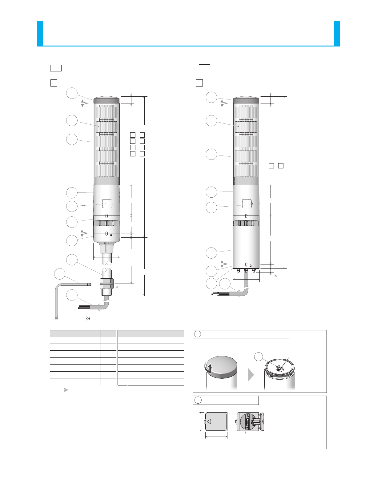
3.2. Part Names and Outer Appearance
Each gure contains 5 lens tiers, with Flashing/Alarm functions. For 3 lens tiers, the outer lens height will be shorter. Also, for
models not including the Flashing/Alarm functions, the product will not include an alarm unit.
φ60
12
(Unit:mm)
Wire length: 1360
Wire style: UL2464/AWG24
40
70
<
Overall Height
>
- :320
- :254
- :280
- :214
16
10
8.5
1
Maximum Board thickness: 4 mm
2
Spec. Underside View
1
3
4
6
7
910
2
5
φ60
1
40
70
16
20
8.5
1
3
4
6
8
9
2
5
14
Direct mount
with cable connection
■Direct mount with Screwless Terminal
Block connection
■
B
B
N
N
5
3
5
3
<
Overall Height
>
- :330
- :264
- :290
- :224
B
B
N
N
5
3
5
3
WJ TN
WJ TN
TN
Accessory Assembly
Screw
(M4x20)
3pcs.
Flanged nut(M4)
3pcs.
Threaded hole for cable gland attachment
(M16×1.5 Effective screw length 12mm)
Cable gland
<Note> The cable gland is not included
with this product.
(φ6.5)
24V DC Type
D24V DC Type
D
8
LA6 Signal Tower Complete Operation Manual
φ60
1
Wire length: 1360
Wire style(Power): UL1007/AWG18
Wire style(Signal): UL1061/AWG24
110
70
<
Overall Height
>
- :390
16
10
8.5
1
3
4
6
7
910
2
5
Direct mount
with cable connection
■
B5
WJ
(φ8.5)
3
Maximum Board Thickness: 16 mm
φ60
40
70
284
~
294
313.5
16
10
1
3
4
6
7
10
12
2
5
[ Steel pole with mounting angle and cable
■
11
3
<
Overall Height
>
- :320
- :254
- :280
- :214
B
B
N
N
5
3
5
3
LJ
Wire length: 1060
Wire style: UL2464/AWG24
(φ6.5)
[ 24V DC Type
D[ 100V - 240V AC Type
A
Remove the head cover by turning it to the left to release it from the locked
position.(To re-assemble, perform the steps in the reverse order.)
13 Multi-function Button(Remove Head Cover)
18.8
22.2
5
(Cover in opened position)
USB Cover (Detailed Parts)
Micro USB connector
(Micro-B Female)
〈Note〉
- To open the USB Cover, insert a
minus driver (blade-edge width of 3
mm, thickness of 0.5 mm or less) in
the indented part and lightly pry it
open.
(Use an object made of ceramic to
avoid scratching or damaging the
Body.)
- Ensure the USB cover is closed at
all times. If not securely closed,
the waterproof performance will
decrease.
13 〈Note〉
This connector
is not used.
〈Note〉 The arrow mark (stackable mark) shows the part of the Main Unit
(upper portion of bracket) which can be removed.
Do not disassemble any parts other than the parts indicated above.
Number Name Material
1Head Cover ABS
2Lens PMMA
3Outer Lens PC
4Body ABS
5 USB Cover ABS
6Buzzer Case ABS
7Direct-mount Bracket ABS
Number
Name Material
8
Terminal Block Bracket
ABS
9
Waterproof Packing
Urethane Foam
10
Cable
PVC
11
Pole
Steel Pipe
12
14
Mounting Angle
Steel Plate
Accessory Assembly
Steel
13
Multi-function Button
ABS
9
LA6 Signal Tower Complete Operation Manual
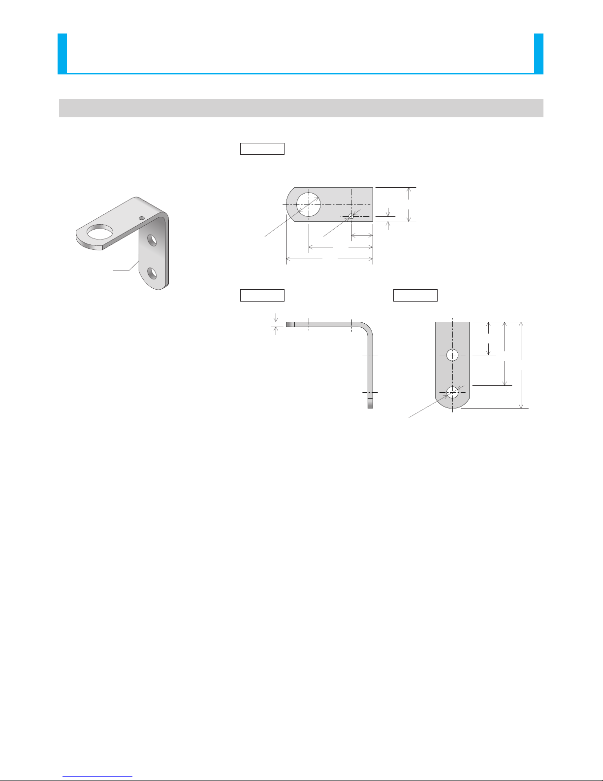
3.3. Attachment Angle Part Names and Dimensions
(Unit: mm)
32
5
4.5
31
81
66
Top View
Side View Rear View
60
20
81
2-
φ11
‘L’ Bracket
φ22.5
φ5
10
LA6 Signal Tower Complete Operation Manual
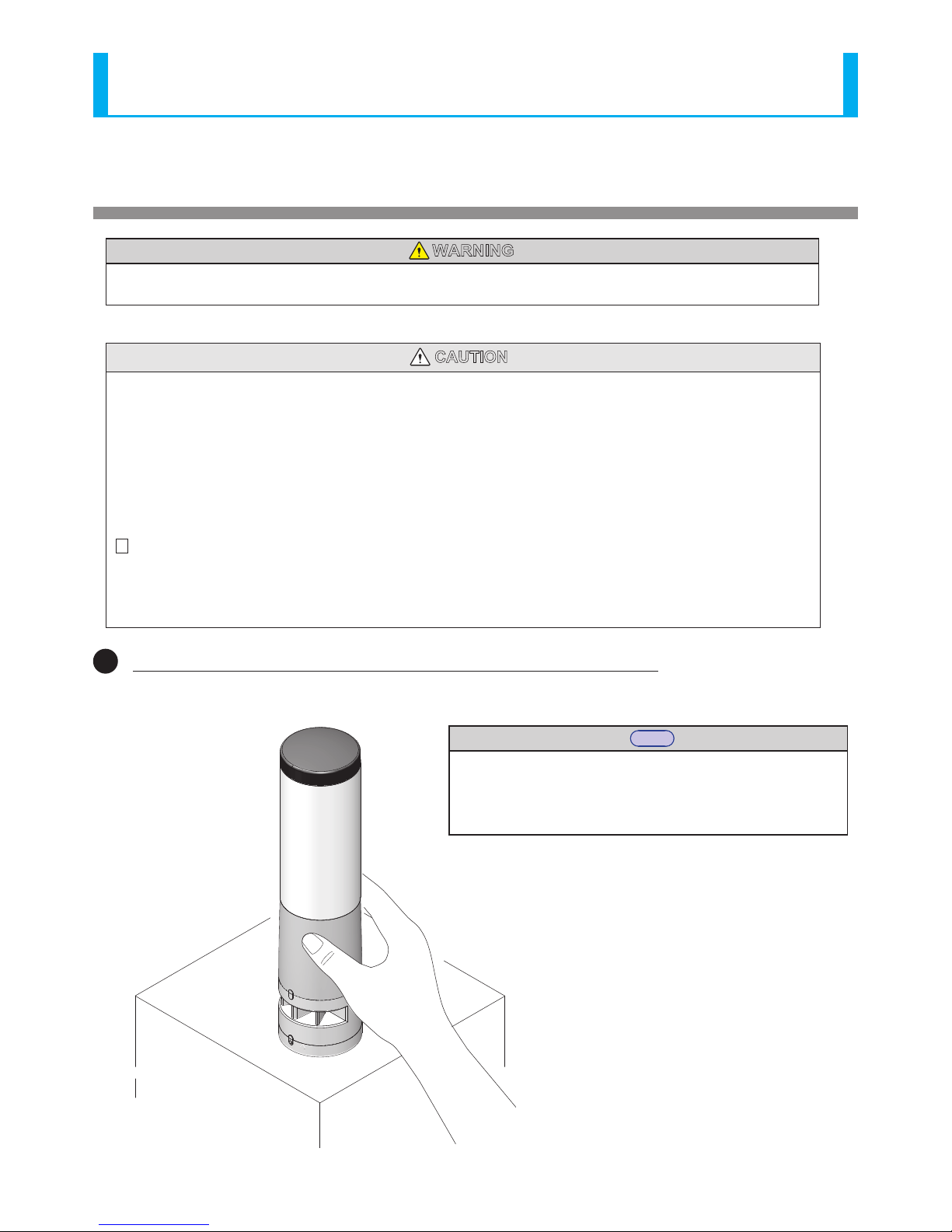
4. Mounting Direction
WARNING
• The product should be turned off and the power supply disconnected prior to installation. Failure to comply may
result in electric shock.
CAUTION
• The clamping surface should be sucient enough to tolerate the weight and surface of the product. Do not use the product
in a place where vibrations exceeds the specications. Failure to comply may result in the product detaching and falling,
causing injury to passers-by, etc.
• Only install the signal tower in an upright or inverted position. Failure to comply may result in the product detaching and
falling, causing injury to passers-by, etc.
• Use a soft cloth, etc., dampened with water to wipe the main unit. If wiped with chemicals outside water (thinner, benzine,
gasoline, oil, etc.), product damage may occur.
• Do not disassemble this product beyond it’s usable parts (refer to “3.2 Part Names and Outer Appearance” on page 7).
Failure to comply may result in product breakage due to disassembly.
[ D DC24V Type]
• This equipment complies with FCC regulation part 15 for class A digital products, and applies to the following restrictions.
These restrictions are limited to cases where this equipment is operated in a business district, and it is designed to take the
relevant protective measures against electromagnetic noise hindrance.
• This product must not be used in residential areas.
1Check the installation location for the product before mounting
Note
• Check whether it interferes with any other objects.
• Check whether wiring can be easily done.
• Check to be sure the USB Cover can be opened and closed.
• Check whether the alarm direction is correctly suitable.
(B: Flashing/Alarm Type)
11
LA6 Signal Tower Complete Operation Manual
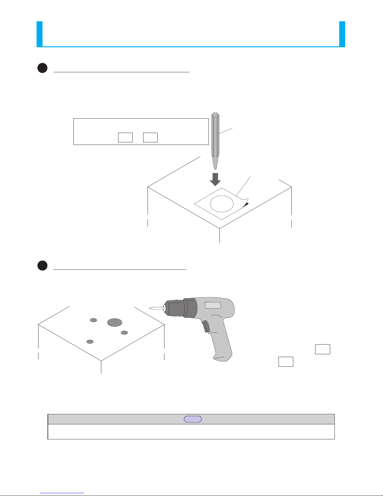
2Marking holes for wiring and installation
Use the “Installation Template” pattern (Refer to the Instruction Manual [Maintenance Version]), and mark holes with a punch,
etc.
3Making holes for wiring and installation
Use a drill, etc., to make holes for installation and wiring.
Punch etc.
Installation Template
WJ
TN
<Note>
Figure is for or installations.
Drill etc.
WJ
TN
<Note> Figure is for
or installations.
Note
• To continue from procedure ➌, refer to the model type (WJ), (TN), (LJ) for procedure ➍to continue the mounting
and wiring installation.

12
LA6 Signal Tower Complete Operation Manual
Assemble the body ( N type)
or alarm unit (B type)
Fix the Terminal Block
bracket in place with a nut.
5
6
4
5
7
Attach the wires
6
Use waterproof sealant if needed.
8
Point 1
Point 2
With the body ( type), or
alarm unit ( type), turn it to
the right to remove. B
N
(Refer to )
(Refer to “5. Wiring”)
Point 1
Use sealant to prevent water intrusion.
(from the mounting under-side)
If the installed environment exposes water, etc.,
to the under-side of the mounting surface, be
sure to use sealant on the mounting and
distribution holes.
When not using an attachment
angle, make a fitting hole of
∅22-23mm.
Model Steel pole with Mounting angle and Cable
LJ
Mounting
Surface
35mm
12.2 N.m(Standard)
Recommended Torque
30 N.m(Standard)
Recommended Torque
Threaded hole for cable gland attachment
(Effective Screw Length for M16x1.5 is 12 mm in length)
B
N
〈Notes〉
Do not pull the lead wire
connected to the Terminal
Block bracket and body
(or alarm unit).
Model Direct Mount/Screwless Terminal Block
TN
4
(Use the “Installation Template” on
Pg. 29 of the Instruction Manual)
Feed the wiring through the hole and
set the pole in place to install.
Drill Hole (∅11mm in two places)
(Use the Installation Template on
Pg.29 of the Instruction Manual)
Use commercially available M10
nuts and bolts to fasten with.
0.75 N.m(Standard)
Recommended Torque
Thread the wires through the wiring hole.
Insert a mounting bolt into the installation hole.
4
Attach the mounting nut from the back-side.
5
Use waterproof sealant if needed.
6
(Refer to )
Point 1
(Use Installation Template on Pg.29 of
the Instruction Manual)
0.75 N.m(Standard)
Recommended Torque
Model Direct mount and Cable
WJ

13
LA6 Signal Tower Complete Operation Manual
5. Wiring
WARNING
• The power supply should be turned o prior to wiring, at any cost. Failure to comply may result in electric shock.
• Be sure the wiring is correct. If an error is made in wiring, the internal circuit will be damaged and may cause a re.
• When transferring data via USB connection, do not allow the supply voltage from this product to contact with the personal
computer, or it’s peripheral devices. Failure to comply will result in product damage due to combustion or re.
- As an example, if the positive power terminal is connected to ground and the personal computer, FG (housing), which
in turn, makes a connection with this product via the USB connection, it should not be grounded because of the reverse
polarity. There are some personal computers which have the USB port connector and negative terminal of the personal
computer in contact with the FG (housing). Personal computers with such USB connections made, should have the FG
(housing) of the personal computer and the negative terminal of the USB port of the product connected. If the case is
where the personal computer has the metal part as the positive grounding of the supplied power source to the product,
the product will have a 24V potential applied to the negative terminal of the USB port of the product, thus will lead to
damage of the product by burning.
CAUTION
• Strip 9mm (±1mm) of wire insulation from the wire to insert it in the Terminal Buss. If longer than this, it may result in electric
shock or short-circuiting. (For (TN) Direct Mount/ Terminal Buss)
• Wire the product so that the lead wire does not protrude from the terminal. Failure to comply may result in electric shock or
short-circuiting. (For (TN) Direct Mount/ Terminal Buss)
• It is not necessary to connect to an external lead for tiers not used. When an extra lead is not connected, it should be
individually insulated with electrical tape or something similar. Failure to comply may result in electric shock or short-
circuiting.
• Do not pull the lead wire or push it inside the body. Failure to comply may result in product damage or short-circuiting.
• If wiring is extended beyond its factory length, a relevance in the length of the wire and wire gauge will cause a voltage
drop.
[ B Flashing/Alarm Type]
• By all means, do not apply voltage to the“Flashing/Pulse Enable Common” line (Refer to “5.1. Wiring Examples”on page 14).
Failure to comply may result in damage to the product.
[ A AC 100 - 240V Type]
• Do not apply voltage, or connect the source line to the signal line. Failure to comply may result in damage to the product.
Please
• Be sure to check for proper wiring before connecting the power.
• To counter against noise, shorten all wiring as much as possible, and use shielded wire when possible. In addition, separate
any signal lines which pass along high voltage cables or is susceptible to receive induction noises.
• If a non-voltage contact, such as a relay or switch etc., is used for the power supply line, consider inrush current capacity
when selecting the contact. Contact welding and malfunction will occur if current capacity is insucient.
Note
• Even when starting two or more units simultaneously, a lag will occur during ashing or the Alarm sound.

14
LA6 Signal Tower Complete Operation Manual
5.1. Wiring Examples
The wiring example indicates how to connect to external contacts for every classication.
If there are any special applications that require asking questions concerning this product, feel free to contact your PATLITE Sales
Representative.
■About the “Mode Change” switch-over
When entering the “Mode Change”, the operating mode can be changed to the “Smart Mode.” In the “Smart Mode”, various
lighting and alarm patterns can be arranged. Visit our company’s homepage (http://www.patlite.com) for further details.
* For the “Mode Change” switch-over, refer to “6. Operating Directions” on page 19 for further details.
Wiring Example Index
LED Tier 1 / Input 1 / ①
Red
Function Name
[Signal Tower] mode/[Smart Mode]
Lead Wire Color
(Cable Specication)
PIN No.
( Direct Mount/
Screwless Terminal
Block Type)
TN
Screwless Terminal Block Connector PIN Arrangement
( Direct Mount/ Screwless Terminal Block Specifications)
TN
■Recommended lead wire specifications
■Alarm Sound Pattern (Factory Default)
UL1007 / UL1430
Wire Type
Alarm 1
Alarm 2
Alarm 1 and Alarm 2 Entered Simultaneously
Alarm Sound No. 2
Alarm Sound No. 9
0.5~1.5mm2
Wire Gauge (Solid Wire)
AWG20~16
Wire Gauge (Frayed Wire)
1
Red
2
Orange
3
Green
4
Blue
5
White
6
Gray
7
Black
8
Yellow
9
Gray
10
Black
11
Purple
LED1/Input1
LED2/Input2
LED3/Input3
LED4/Input4
LED5/Input5
Alarm 1/Input6
Alarm 2/Input7
Power Wire
Flashing
/Pulse Enable Common
Power Line
(Signal-line Side)
Mode Change
Alarm Sound No. 1
→Refer to the "Screwless
Terminal Block connector
PIN arrangement” gure on
the right.
<Note> The lead wire color does not indicate the
LED luminescence color.
・Temperature rating should be above 750C and the conductor material should
be of copper wire.
1
2
3Point
Screwless Terminal Block wiring method (Model Direct Mount/ Screwless Terminal Block)
Lever
・The minus driver blade should be at least 2.5mm by 0.4mm
in size.
・Do not forcibly push the lever more than necessary with the
driver. Failure to comply may damage the unit.
・Strip 9mm (plus or minus 1mm) of wire insulation from the
wire to insert it in the Terminal Block.
・
When removing the lead wire, do not just pull to remove.
(Be sure to operate the lever to release the lock.)
The driver is removed to
release the lever.(Check to
make sure the lead wire has
been locked in place.)
A minus driver etc. is used to pry the
lever slot of the Terminal Block open,
by pushing straight onto the lever slot.
The stripped side of the lead
wire is inserted in the slot.
TN
CAUTION
• When lighting and ashing are used together in the Signal Tower mode with a PLC, it is necessary to separate the ashing and non-
ashing circuit outputs on the PLC side.

15
LA6 Signal Tower Complete Operation Manual
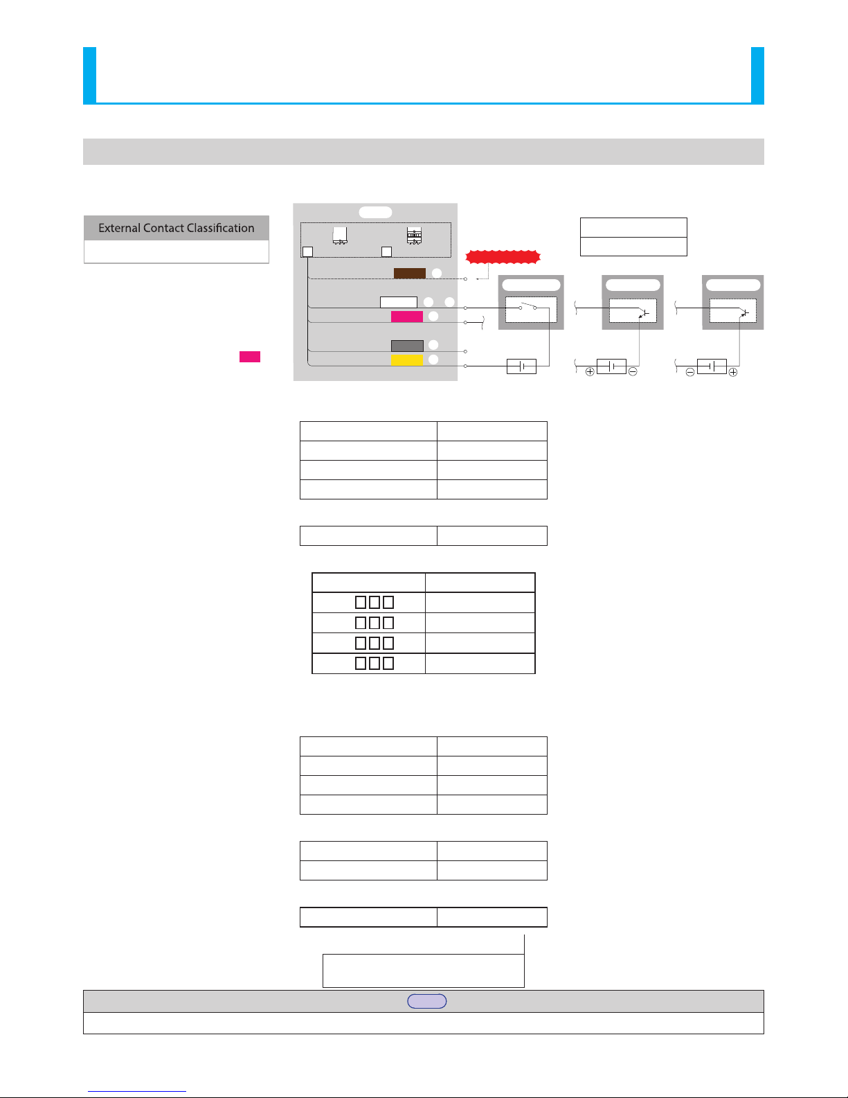
5.1.2. Connecting to a PLC (NPN) [DC 24V Type]
5.1.1. Connecting to Relay Contacts [DC24V Type]
PLC
E
CB
Circuit Schematic
PLC (NPN Transistor)
Do Not Apply Voltage!
24V DC
(
Class 2
)
/
/
/
/
/
/ ⑥
/ ⑪
/ ⑩
/ ⑧
①
②
⑤
④
③
LA6
LED Tier 1 / Input 1
LED Tier 2 / Input 2
LED Tier 3 / Input 3
LED Tier 4 / Input 4
LED Tier 5 / Input 5
Power Supply Wire
Flashing/Pulse Enable
Common line
Alarm 1 / Input 6
Mode Change
Power Supply Wire
/ ⑦
Alarm 2 / Input 7
Without ashing/alarm
BN
With ashing/alarm
/ ⑨
Output Unit 2
For Flashing/Pulse Enable
Output Unit 1
For Lighting
Red
Orange
Green
Blue
White
Brown
Purple
Pink
Skyblue
Yellow
Gray
/
/
/
/
/
/⑥
/⑪
/⑩
/⑧
①
②
⑤
④
③
LA6
24V DC
(
Class 2
)(
No polarity
)
LED Tier 1 / Input 1
LED Tier 2 / Input 2
LED Tier 3 / Input 3
LED Tier 4 / Input 4
LED Tier 5 / Input 5
Power Supply Wire
Flashing/Pulse Enable
Common line
Alarm 1 / Input 6
Mode Change
Power Supply Wire
/⑦
Alarm 2 / Input 7
External Contact
For Flashing/ Pulse Enable
External Contact
For lighting
Do Not Apply Voltage!
External Contact Classication
Voltage Contact Relay
Without flashing/alarm
BN
With flashing/alarm
/⑨
Red
Orange
Green
Blue
White
Brown
Purple
Pink
Skyblue
Yellow
Gray

16
LA6 Signal Tower Complete Operation Manual
5.1.3. Connecting to a PLC (PNP) [DC 24V Type]
PLC
〈Note〉Since ashing and intermittence are
uncontrollable with the PNP type
transistor, do not connect it.
Control ashing and intermittence
with the PLC programming.
24V DC
(Class2)
/
/
/
/
/
/⑥
/⑪
/⑩
/⑧
①
②
⑤
④
③
LA6
LED Tier 1 / Input 1
LED Tier 2 / Input 2
LED Tier 3 / Input 3
LED Tier 4 / Input 4
LED Tier 5 / Input 5
Power Supply Wire
Flashing/Pulse Enable
Common line
Alarm 1 / Input 6
Mode Change
Power Supply Wire
/⑦
Alarm 2 / Input 7
Without flashing/alarm
BN
With flashing/alarm
/⑨
External Contact Classication
PLC (PNP Transistor)
Do Not Apply Voltage!
Circuit Schematic
E
CB
Brown
Red
Orange
Green
Blue
White
Purple
Pink
Skyblue
Gray
Yellow

17
LA6 Signal Tower Complete Operation Manual
E
CB
Circuit Schematic
PLC (NPN Transistor)
Do Not Apply Voltage!
/
/
/
/
/
/ ⑥
/ ⑪
/ ⑩
/ ⑧
①
②
⑤
④
③
/ ⑦
/ ⑨
Output Unit 2
For Flashing/Pulse Enable
Output Unit 1
For Lighting
Red
Orange
Green
Blue
White
Brown
Purple
Pink
Skyblue
Yellow
Gray
100 ~ 240V AC
Fuse
1A
PLC
B
LA6-5A
LED Tier 1 / Input 1
LED Tier 2 / Input 2
LED Tier 3 / Input 3
LED Tier 4 / Input 4
LED Tier 5 / Input 5
Power Supply Wire
Flashing/Pulse Enable
Common line
Alarm 1 / Input 6
Mode Change
Power Supply Wire
Lighting Common line
Alarm 2 / Input 7
With Flashing/Alarm
L N
5.1.5. Connecting to a PLC (NPN) [AC 100 -240V Type]
5.1.4. Connecting to Relay Contacts [AC 100 -240V Type]
/
/
/
/
/
/⑥
/⑪
/⑩
/⑧
①
②
⑤
④
③
/⑦
External Contact
For Flashing/ Pulse Enable
External Contact
For lighting
Do Not Apply Voltage!
External Contact Classication
Voltage Contact Relay
/⑨
Red
Orange
Green
Blue
White
Brown
Purple
Pink
Skyblue
Yellow
Gray
LED Tier 1 / Input 1
LED Tier 2 / Input 2
LED Tier 3 / Input 3
LED Tier 4 / Input 4
LED Tier 5 / Input 5
Power Supply Wire
Alarm 1 / Input 6
Mode Change
Power Supply Wire
Alarm 2 / Input 7
Flashing/Pulse Enable
Common line
B
With Flashing/Alarm
LA6-5A
Lighting Common line
100 ~ 240V AC
Fuse
1A
L N
18
LA6 Signal Tower Complete Operation Manual
5.2. Current Capacity
5.2.1. Contact Capacity [DC 24V Type]
Table 1 Signal Contact Capacity
Current Capacity 100mA or more
Withstand Voltage DC 35V or more
Leakage Current 0.1mA or less
ON Voltage (Vsat) 1V or less
Table 2 Power Supply Inrush Current
Inrush Current Value 16A/5us
Table 3 Supply Current
Model Current
LA6-3D N 170mA
LA6-3D B 210mA
LA6-5D N 260mA
LA6-5D B 300mA
5.2.2. Contact Capacity [ AC 100 - 240V Type]
Table 1 Signal Contact Capacity
Current Capacity 100mA or more
Withstand Voltage DC 35V or more
Leakage Current 0.1mA or less
ON Voltage (Vsat) 1V or less
Table 2 Power Supply Inrush Current
Inrush Current at 25oC 16A/2ms
Inrush Current at 50oC 50A/2ms
Table 3 Power Consumption
LA6-5AWJWB 7.5W
Table 4z Fuse Ratings
250V/ 1A
5 x 20mm Fast-blow Glass Tube Fuse
24V DC
(Class2)
(
No polarity
)
LA6
Relay
PLC (NPN)
/⑨
Each LED/Alarm
Input1 - 7 /
~
①⑦
Do not connect!
24V DC
(Class2)
PLC (PNP)
24V DC
(Class2)
16 A , 5 µsec
Inrush Current
Voltage Contact Relay or PLC
Without ashing/alarm
BN
With ashing/alarm
Flashing/Pulse Enable
Common line
/⑪
/⑩
/⑧
Power Supply Wire
Mode Change※
Power Supply Wire
Pink
※There is no inrush current on the wire
for“Mode Change.”
Each Color
Pink
Yellow
Gray
Brown
Note
• When a regulated power supply is not being used, select a fuse that meets class CC or more.
19
LA6 Signal Tower Complete Operation Manual
6. Operating Directions
This product contains a multi-function button (Refer to”3.2. Part Names and Outer Appearance” on page 7) under the Head
Cover in the upper section, which can be operated as follows:
- Alarm Sound Control: Adjustable up to four steps.
- LED Color Change: The luminescence color of each tier can be changed.
- Version Conrmation: The current version of the product can be checked.
- Product Initialization: The memory contents of the product can be cleared and returned to factory default values.
(Returns to the “Signal Tower” mode. The alarm sound pattern and the “Smart Mode” setup conditions have not changed.)
The operation of this product contains two modes; “Signal Tower” mode and “Smart Mode.” The explanation for each mode
shows fairly signicant dierences to them.
Changing between the “Signal Tower” mode and the “Smart Mode” is a simple ON/OFF input from the “Mode Change” signal
input wire.
Signal input “Mode Change” ON: Smart Mode
Signal input “Mode Change” OFF: “Signal Tower” mode
Although a continuous hold input controls the inputs, only a trigger input in the pulse trigger mode for the “Smart Mode”
turns into a one shot input. With the “Mode Change” in the OFF condition, the Multi-function button can be used for the
recombination of colors, changing the amount of alarm sounds, and other product functionalities.
6.1. “Signal Tower” mode
The “Signal Tower” mode controls operation with ON/OFF inputs from the wires currently assigned to each LED and alarm, like
our conventional Signal Towers. When short-circuiting each input to the “Flashing/Pulse Enable Common”, The LED will ash,
and an intermittent alarm sound will occur.
The “Signal Tower” mode set up can be done in our “EDITOR for LA series” software application (Visit our homepage at http://
www.patlite.com/ to download the software.).
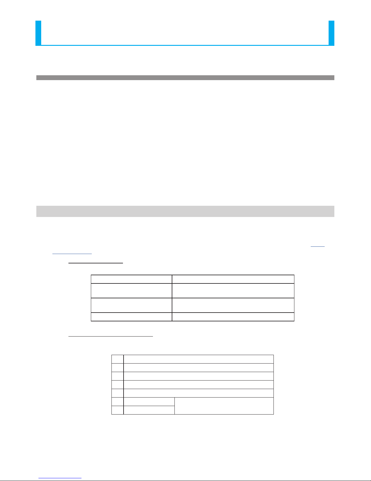
• Setup Parameters
This mode has parameters that can be set up as shown in the following table.
Setup Index Description
LED lighting/ashing for ash per
minute(fpm) rate
Flashing rates are selectable from 30fpm, 60fpm, or
120fpm.
Alarm Tone Alarm sound muting or one tone can be selected from
11 varieties.
LED Color LED lights can be selected for ON or OFF.
• LED Input Conversion Table
For inputs 1-7, LED and Alarm ON/OFF can be entered as indicated in the “Signal Tower” mode operation example.
Table 4. “Signal Tower”mode Input Conversion Table
1 LED Tier 1 (Red)
2 LED Tier 2 (Amber)
3 LED Tier 3 (Green)
4 LED Tier 4 (Blue)
5 LED Tier 5 (White)
6 Alarm 1 Tone No.1 Alarm 3 Tone No.9
* When inputs are simultaneously entered
7 Alarm 2 Tone No.2
* Pre-set with Factory default

20
LA6 Signal Tower Complete Operation Manual
• “Signal Tower” mode operation example
6.2. “Smart Mode”
There are three kind of modes, ““Time-trigger” mode”, ““Pulse-trigger” mode”, and “Single-display” mode”.
The factory default input is the “Time-trigger” mode, but there is a “Pulse-trigger” mode and “Single-display” mode, of which
each type can be changed by the setup, which means it is necessary to create the setup data and transmit it to the product with
a personal computer which has the “EDITOR for LA series” software application (Visit our homepage at http://www.patlite.com/
to download the software.) installed in it. (Refer to “7. Changing Data” on page 37 for details on how to change the data)
For details, please refer to the software help section.
The main mode has common functions for each type and has the following at this mode.
• Input 6 (“Mute”input)
The alarm sound stops when an “ON” input occurs, and mues the sound.
• Input 7 (“Clear”input)
If an input for each type is set to ON, the pattern contents which are controlling the operation will be initialized and it will return
to the rst pattern. Also, LED’s from all the tiers will go out at an “ON” input, and the alarm is also mued.
Refer to each mode for the explanation of how their “Clear” input should look.
6.2.1. “Time-trigger”mode
The “Time-trigger” mode has 63 set patterns to which the memory contains two or more patterns used as a series of wave-like
ows, etc. that can be used in groups. The “Time-trigger” mode operates in accordance with time, and the pattern transition
timing operates during this group operation. In addition, the maximum memory of 15 groups can be set up in ON/OFF
combinations, and a call is made to inputs 1-4.
Moreover, the “Time-trigger” mode for input 5 turns into a “STOP” input, and during the input, operates by either one of the
following conditions indicated below, and stops the time progress of the pattern changes.
- “STOP” input of a pattern currently on display to change to a lighted state.
- “STOP” input of a pattern currently on display to change to a ashing state.
- “STOP” input of a special pattern currently on display to change to a lighted state.
- “STOP” input of a special pattern currently on display to change to a ashing state.
The setup to select these can be performed in the “EDITOR for LA series” software application (Visit our homepage at http://
www.patlite.com/ to download the software.).
Operating
Condition
LED Tier 1 OFF Blue OFF OFF OFF OFF
...
Red Red Red
Red Flashing
OFF
LED Tier 2 OFF Blue Blue OFF OFF OFF Red Red Red
Red Flashing
OFF
LED Tier 3 OFF Blue Blue Blue OFF OFF Red Red Red
Red Flashing
OFF
LED Tier 4 OFF Blue Blue Blue Blue OFF OFF Red Red
Red Flashing
OFF
LED Tier 5 OFF Blue Blue Blue Blue Blue OFF Red Red
Red Flashing
OFF
Buzzer
Mute
Tone 1 Tone 2 Tone 7
Mute Mute Mute Mute
Tone 11 Tone 13
Mute
Group/Pattern No. 1/1 1/2 1/3 1/4 1/5 ... 1/60 1/61 1/62 1/63
Signal Input Input 1
Input 2
Input 3
Input 4
Input 5 (STOP)
Input 6 (Mute)
Input 7 (Clear)
CAUTION
• Do not use the “Flashing/Pulse Enable” signal line when in the “Smart” mode..
Other manuals for LA6 series
1
Table of contents
Popular Light Fixture manuals by other brands

Lightolier
Lightolier ProSpec 26030 specification

Lightolier
Lightolier Lytespan 8292F3E specification

Lightolier
Lightolier ProSpec Track Lighting installation instructions

Chauvet DJ
Chauvet DJ EZ Pin IRC Quick reference guide

Cooper Lighting
Cooper Lighting Metalux RK Series Specifications

SELF Electronics
SELF Electronics FLEX2 Series instruction manual

Cooper Lighting
Cooper Lighting Halo L1760 Specification sheet

Lightolier
Lightolier Lytespan 7531 specification

Lightolier
Lightolier BI-LYTER specification

RAB Lighting
RAB Lighting WP1LED installation instructions

Blizzard Lighting
Blizzard Lighting Blade RGBW user manual

Euri
Euri ECR-55W103s installation guide


