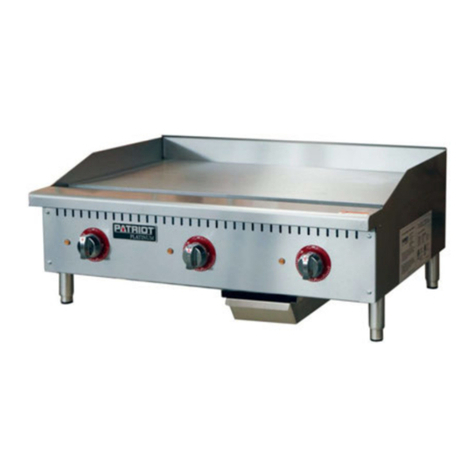
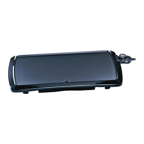
Patriot PLATINUM User manual

This manual contains important information regarding your unit. Please read this manual
thoroughly prior to equipment set-up, operation and maintenance. Failure to comply with regular
maintenance guidelines outlined in this manual may void the warranty.
INSTRUCTION MANUAL
Thermostatic Gas Griddles

March 2016
WARNINGS
• Do not store or use gasoline or other flammable vapors or liquids in the vicinity of this or any other equipment.
• Improper installation, adjustment, alteration, service or maintenance can cause property damage, injury or death.
• Read the installation and maintenance instructions thoroughly before installing or servicing this equipment.
• Have the equipment installed by a qualified installer in accordance with all federal, state and local codes.
• Do not install or use without all 4 legs.
• This equipment is for use in non-combustible locations only.
• Do not obstruct the flow of combustion and ventilation air.
• Do not spray controls or the outside of the equipment with liquids or cleaning agents
• Allow for hot parts to cool before cleaning or moving.
• This equipment should only be used in a flat, level position.
• Do not operate unattended.
• Any loose dirt or metal particles that are allowed to enter the gas lines on this equipment will damage the valve and
affect its operation.
• If you smell gas, follow the instructions provided by the gas supplier. Do not touch any electrical switch; do not try to
light the burner; do not use a telephone within close proximity.
SET-UP
1. Remove all packing material and tape, as well as any protective plastic from the equipment.
2. Place the equipment in the desired position and height.
3. Install the four (4) legs onto the equipment.
4. Clean and dry the equipment thoroughly before using.
BEFORE INSTALLATION
• Installation of this device should be done by professional technicians
• This device is suitable for area whose altitude is lower than 6,500 ft. If it is higher than this altitude, please contact
the manufacturer.
• Installation of this unit should conform to provisions of gas safety, installation and usage
• This device should be kept a minimum clearance of 4” away from non-combustible objects on both sides and 6” at
the back (e.g. walls, windows etc.). Do not install on a flammable floor or around other combustible objects.
TO INSTALL - Please read manual thoroughly before installation and operation
1. Select a location for the unit that has a level, solid, non-skid surface that is non-flammable.
2. Screw legs into the permanently fastened nuts on the four corners of the unit and tighten by hand. Legs must be
installed for proper ventilation to the unit.
3. Level unit by adjusting the four feet and tighten securely. The adjustable feet have an adjustable range of one inch.
Do not slide unit with the legs mounted. Lift if necessary to move unit.
4. The supplied gas pressure regulator is factory set at 4” Natural Gas W.C or 10” Propane Gas.
5. Do not obstruct the flow of combustion and ventilation air under the unit by the legs or behind the unit by the flue.
Do not place objects between the bottom of the unit and countertop.
6. There must be adequate clearance for removal of the front panel. All major parts except the burners are removable
through the front if the gas is disconnected.
7. It may be unnecessary to adjust the balance of gas volume and air supply to each burner. This must be done by an
authorized service technician.
CODES AND STANDARDS
This item must be installed in accordance with:
In the United States:
State and local codes, or in the absence of local codes, with:
National Fuel Gas Code, ANSI-Z223.1/NFPA #54 (latest edition). Copies may be obtained from The American Gas
Association Accredited Standards Committee Z223, @ 400 N. Capital St. NW, Washington, DC 20001 or the Secretary

March 2016
Standards Council, NFPA, 1 Batterymarch Park Quincy, MA 02169-7471.
NFPA Standard #96 Vapor Removal from Cooking Equipment, latest edition, available from the National Fire Protection
Association, Batterymarch Park, Quincy, MA. In the commonwealth of Massachusetts all gas appliances vented through
a ventilation hood or exhaust system with a damper or with a power means of exhaust shall comply with 248 CMR.
In Canada:
Local codes:
CAN/CSA-B149.1 Natural Gas Installation (latest edition).
CAN/CSA-B149.2 Propane Installation Code (latest edition), available from the Canadian Gas Association 178 Rexdale
Blvd., Etobicoke, Ontario Canada M9W 1R3.
The installer of this unit should be aware of state, county or local code for connecting this equipment to determine if an
external regulator is required
Clearance and positioning around the equipment:
This equipment must be installed adjacent to non-combustible surfaces only with a minimum spacing of 6” from all
sides. This equipment must be a distance of 6” from other equipment. The equipment must have the 4” legs installed
and be placed on a non-combustible surface.
Air Supply and ventilation:
The area in front and around the equipment must be kept clear to avoid any obstruction of the flow of combustion and
ventilation air.
Adequate clearance must be maintained at all times in front of and at the sides of the equipment for servicing and
proper ventilation.
Pressure Regulator:
All commercial cooking equipment must have a pressure regulator on the incoming service line for safe and efficient
operation. The regulator provided for this equipment is adaptable for both Natural gas and LP gas.
Regulator specifications: ¾” NPT inlet and outlet, factory adjusted for 4” WC Natural Gas standard and may be
converted by qualified personnel to be used for Propane at 10” WC.
GAS CONVERSION:
Conversion from Natural Gas to Liquid Propane (LP) or vice versa may only be performed by the factory or its authorized
service agent. In case of troubleshooting, ensure the correct orifice sizes of the tips have been provided.
Orifice size is marked on the tip.
Natural Gas Orifice is #36
Liquid Propane Gas Orifice is #50
Gas Connection: The appliance comes fitted with a ¾” NPT (National Pipe Thread) male adapter for connection to the
pressure regulator.
Maintenance: A qualified service company should check the unit for safe and efficient operation on an annual basis.
Contact the factory representative or local service company to perform maintenance and repairs.

March 2016
Gas Piping: Gas piping shall be of such size and so installed as to provide a supply of gas sufficient to meet the full gas input of
the appliance. If the appliance is to be connected to existing piping, it shall be checked to determine if it has adequate capacity.
Joint compound (pipe dope) shall be used sparingly and only on the male threads of the pipe joints. Such compounds must be
resistant to the action of Liquefied Propane (LP) gases.
Manual Shut Off Valve: A manual shut off valve should be installed upstream from the manifold, within four (4) feet, (1.2M) of
the appliance and in a position where it can be reached in the event of an emergency.
Checking For Gas Leaks: Using a gas leak detector or a soapy water solution is recommended for locating gas leaks. Matches,
candle flame, or other sources of ignition shall not be used for this purpose. Check entire piping system for leaks.
Exhaust Canopy: Cooking appliances inherently create a good deal of heat and smoke and should be installed under an
efficient exhaust hood with flame proof filters. A vertical distance of not less than four (4) feet shall be provided between the
top of the appliance and filters or any other combustible material.
OPERATING INSTRUCTIONS AND CONTROLS
When turning on for the first time please be advised that it might take a little longer to ignite due to the air existing in the pipe.
If the ignition does not light, turn off the ignition switch and wait 3 minutes to try again.
Lighting the Pilot: The manifold units are equipped with a standing pilots and each should be lit immediately after the gas is
supplied to the appliance.
Before attempting to light pilots, turn off the main gas valve to the appliance and wait five (5) minutes to clear the gas.
1. Turn off all gas control knobs
2. Turn on main gas valve and light all pilots.
3. The pilot burner must be lit at the end of the tube. Hold an ignition source through the pilot light hole (D) in the front panel
at the pilot tube. When the flame is established remove ignition source.
4. To shut down the appliance, turn off the main gas valve to the appliance.
NOTE: Smoke appearing on initial use of the appliance is normal. This is a result of the rust preventative coating burning off.
This will occur for at least fifteen (15) minutes during the first use or seasoning process.
Pilot Flame Regulation: The pilot flame on the appliance has been factory adjusted. When adjustment is necessary, adjust the
pilot flames as small as possible, but high enough to light the burner immediately when burner valve is turned to the “HIGH”
setting. Access to the pilot flame adjustment screw is obtained by removing the front panel.
Burner Adjustment: Remove the front panel to gain access. Turn burner valve knob to “HIGH” position. Slowly decrease mixing
ring aperture to give a soft blue flame having luminous tips, then slowly increase opening to a point where the yellow tips
disappear and a hard blue flame is obtained.
COMMISSIONING: Commission of your new Griddle is of the utmost importance. Commissioning is the thorough and methodi-
cal testing of the equipment, subsystems, and systems to ensure that the final product functions properly and safely at the work
site. By identifying any potential problems (i.e.: equipment location, ventilation, local fire/electrical codes, installation, operator
training, and certification) prior to equipment being placed into service, costly outages and potential damages may be avoided.
Operating the Griddle – Pilot Lighting Instructions for THERMOSTAT CONTROLLED GRIDDLES
Before operating Griddle, it should be checked to see that is sitting level. Adjust the feet to level the Griddle. Be sure the catch
tray had been properly placed.
The pilot light on the appliance has been set at the factory. Each burner has a pilot light.
Make sure all knobs are in the “OFF” position.

March 2016
The main gas valve should be “CLOSED/OFF” for five (5) minutes prior to lighting plots to clear any existing gas. (Main gas
valve is supplied by others.)
1. Turn “ON or OPEN” the main gas valve to the unit.
2. Light and hold an ignition source (match) at the pilots. When the flame is established, remove the ignition source.
Repeat this step for each burner as each burner has its own individual pilot. The pilot can be reached through the
holes in the front of the unit.
3. Turn each burner knob “ON”. If the burners do not ignite promptly, turn the knobs “OFF”. From the opening in the front
panel, use a screwdriver and turn the pilot valve screw counterclockwise, which will increase the flame height and
repeat step 4.
If the pilot flame appears large than necessary, turn it down and retest the burner ignition. The pilot flame should be as
small as possible but large enough to guarantee reliable ignition of the burners when the knobs are turned to “ON”. In the
holes located in the front panel are pilot valve adjustments. Use a screwdriver to turn the valve to adjust the flame height
to your desired level.
All burners are lit from constantly burning pilots. Turning the valve to the desired flame height is all that is required to put
the unit in service.
Igniting the Burner:
To ignite the burner, turn knob to the “ON” position, then back off to the desired flame level. The range of adjustment is
virtually infinite between “ON” and “OFF”.On the Thermostat controlled griddle, turn the knob to the desired temperature
and allow it to preheat for approximately fifteen (15) minutes. (*Be sure the griddle plate has been properly season before
attempting to cook). The space between the legs at the bottom admits combustion air. DO NOT BLOCK THIS SPACE.
All burners are lit from a constantly burning pilots. Turning the valve to the desired flame height is all that is required to put
the unit in service. Or if thermostatically controlled, simply set to the desired temperature.
Do not permit fans to blow directly at the unit. Whenever possible, avoid open windows next to the unit’s sides or back.
Avoid wall type fans which create air cross-currents within a room.
It is also necessary that sufficient air should be allowed to enter the room to compensate for the amount of air removed by
any ventilation system. Otherwise, a subnormal atmospheric pressure will occur, affecting operation and causing
undesirable working conditions.
A properly designed and installed hood will act as the heart of the ventilation system for the room or area in which the unit
is installed, and will leave the unit independent of changing draft conditions.
NOTE: It may be necessary to adjust the balance of gas, volume, and air supply to each burner. This must be done by an
authorized service technician.
SEASONING THE GRIDDLE
Be sure to start with a clean Griddle surface. Pour small amount of high quality cooking oil to the griddle plate (about
one ounce (30 cc) per square foot of surface. Spread the oil over the entire griddle surface with a clean cloth to create a
thin film. Turn on the griddle to the lowest flame height or the lowest setting on the dial if it is a thermostatically controlled
griddle, and allow to heat for approximately 30 minutes. As the griddle is heating it will be necessary to spread the oil over
the griddle surface to prevent it from drying. Repeat this process 2 to 3 times gradually increasing the flame height each
time or increase the temperature by turning the dial up 100 degrees at a time, on the burner until the griddle has a slick,
mirror-like surface. This process will take 1 ½ to 2 hours.
Note: Each time the griddle is cleaned with soap and WATER, the seasoning is removed and this process must be
repeated.
Note: If the process occurs too fast the griddle surface may turn a light bluish tint in color. The tint does not hurt the
griddle surface. You should allow the surface to cool and start over.

March 2016
OPERATING THE GRIDDLE
Turn the burners on about 15-20 minutes before cooking for preheating. Set the knobs to the desired flame height or
temperature.
Each valve controls the gas flow to the burner to bring that area of the griddle up to the desired temperature. If different
temperature settings are to be used, adjoining areas should be set to progressively higher temperatures using the lowest
temperature on the outside burners. A uniform and systematic approach to the loading of the unit will produce the most
consistent product results.
CLEANING - NOTE: It is important to check the machine daily. Checking the machine regularly can avoid serious accidents.
Stop using if user feels that there are some problems with the unit. Check the situation of the machine before and after using
every day.
Before using: Is the machine tilted?
Is the control panel damaged?
During use: Is there a strange smell or vibration noise?
Is the flame color of burner normal? Any light back or flameout?
DO NOT use any abrasive or flammable cleaning fluids.
DO NOT hose down, immerse, or pressure wash any part of the Griddle, excluding the catch tray.
NEVER use a scrubber pad (on all exterior surfaces, except the griddle plate), steel wool or abrasive material, or cleaners
containing chlorine, iodine and ammonia, or bromine chemicals as these will deteriorate the stainless steel and shorten the life
of the unit.
IF CLEANING ALL THE GRIDDLE’S SURFACES, THE MAIN GAS VALVE MUST BE SWITCHED TO THE CLOSED POSITION. AFTER
CLEANING, THE GAS LINE CAN BE SWITCHED BACK TO THE OPEN POSITION. PLEASE FOLLOW THE LIGHTING INSTRUCTION IN
THE MANUAL TO RELIGHT THE GRIDDLE’S PILOTS AS NEEDED.
1. Before cleaning, please turn off all gas valves.
2. Please clean the burners and tray for odds and ends regularly.
3. Clean the stainless steel surface with warm soapy water every day and rinse it completely. During cleaning, do not clean
the stainless steel surface with abrasive detergent, brush or scraper etc. The residual iron scale may cause rusting.
4. Do not clean the surface with chlorine cleanser (bleach, hydrochloric acid etc.). Do not clean the floor where the device
locates with corrosive substance.
5. Clean the dirt on the burners and baffle regularly.
6. Do not modify the ventilation volume needed during combustion.
7. Accumulation of the iron substance (e.g. Material that formed by iron rust dissolving in water in the pipe, especially when
the device is not used for a long time.). Therefore, to avoid accumulation of such substance, clean the food swill that is
difficult to clean with stainless steel scraper or brush containing no iron substance instead of steel brush.
8. Accumulation of substance containing acidic ingredient, e.g. vinegar, lemon juice, spices, salt etc. Thus, please keep these
substances away from long contacting with the stainless steel accessories. Vapor of acid solution will damage the surface
of the device seriously.
9. A complete cleaning every day will ensure a good service and extend the service life of the unit. Clean the unit with a wet
towel containing suds or a detergent, rinse it with water and dry it with a clean cloth. Do not clean the device with steel
brush, which may cause rust. Similarly, do not contact the unit with substance containing iron.
10. Splotch and abrasion of the stainless steel surface: Scrape and black stain can be cleared away by artificial sponge. During
cleaning, the direction should be the same as the polishing.
11. Rusting: To remove the rusting, please contact the industrial detergent manufacturer to find a proper detergent to remove
such rusting. Industrial rust removal products may do. After cleaning, rinse it with clear water. If necessary, neutralize the
residual acid chemical compound with alkaline detergent.
12. To avoid rusting of the unit, please make sure that the residual salt inside or outside the device is cleared away.
13. After cleaning, to avoid short-time incomplete combustion, the fire hole of the burner should be clear.
14. If not going to use the item at any time, please turn off the gas valve upstream the device or the power main switch.
15. If not going to use the device for a long time, please clean the stainless steel surface with a gasoline cloth and store it in a
well-ventilated area without corrosive gas.
16. 90% of the device is metals (stainless steel, iron, aluminum, galvanized metal sheet) which can be recycled by appointed
treatment plant according to environmental standards of the equipment installation countries.
March 2016
Problem Possible Causes Solution
Griddle not lighting Main gas line is closed Open valve
Griddle not lighting Quick disconnect not inserted all
the way
Check quick disconnect and
make sure it is fully inserted into
female coupling
Griddle not lighting Pilot is not lit Ignite pilot light
Griddle not lighting Cause Unknown Call for service
Problem Possible Causes Solution
Pilot light not staying lit Flame is too low Adjust pilot light flame height
Pilot light not staying lit Pilot tube clogged Replace pilot tube and call for
service
Problem Possible Causes Solution
Strong smell of gas in cooking area Main gas line leak
Turn off main gas valve and DO
NOT LIGHT FLAME, ignite any-
thing or turn/switch on anything
electrical.
Strong smell of gas in cooking area One or more of the pilots may be
out or burner knob turned on
Check to see if burners and
pilots are lit. If not, turn off all
burner valves and main gas
valve and wait for excess gas to
dissipate. Re-attempt to light
pilots after allowing excess gas
to clear
Problem Possible Causes Solution
Cooking surface is heating up
slowly Carbon buildup on griddle surface Clean griddle surface
Cooking surface is heating up
slowly Cause unknown Call for Service
TROUBLESHOOTING

March 2016
Parts Diagram for the Gas Griddles

March 2016
Parts List for the Gas Griddles
DRW. NO. Part Description
1 TOP REAR BEAM
2 LOWER REAR SHROUDING
3 BACK SIDE PANEL (COAMING)
4FRONTPLATEN
5GASVALVE
6 NOZZLE
7PILOT
8U-SHAPEDBURNER
9 RIGHT SIDE PANEL (COAMING)
10 FLUE PANEL
11 SUPPLY PIPE (PILOT)
12 LOCATION PIN (GRIDDLE PLATE)
13 NG/LPG REGULATION VALVE
14 GAS INLET PIPE
15 FIXED PLATE (BURNER)
16 RIGHT SIDE PANEL (EXTERNAL HOUSING)
17 RIGHT SIDE PANEL (INTERNAL HOUSING)
18 LOWER FRONT BEAM
19 FRONT PANEL
20 FRONT HEAT SHIELD
21 OIL TRAY
22 RIGHT GUIDE RAIL
23 LEFT GUIDE RAIL
24 ADJUSTABLE LEG
KNOB˄blue sticker˅
KNOB˄black sticker˅
26 SIDE PANEL 1 (DRIP PAN)
27 SIDE PANEL 2 (DRIP PAN)
28 TRANSITION JOINT
29 LEFT SIDE PANEL (EXTERNAL HOUSING)
30 LEFT SIDE PANEL (INTERNAL HOUSING)
31 FIXED PLATE (PILOT)
32 LEFT SIDE PANEL (COAMING)
33 GRIDDLE PLATE
34 PROBE FIXER
25

National Service America • 230 Park Ave, Suite 1000 • New York, NY • 10169
(Name of Business)
(Model Number) (Serial Number)
(Address) (City) (State) (Zip Code)
(Dealer Purchased From)
This is to inform that I, __________________________________________________________
have had the above installed in my place of business _____________________
(Contact Phone Number) (Contact E-mail) (Signature of individual who owns Business)
The above warranties are in effect from this installation date, or 90 days, which ever comes fi rst.
WARRANTY
REGISTRATION
CARD
MAIL CARD
IMMEDIATELY
This card must be
mailed immediately
after installation date
for warranty to be in
effect.
(Please print name of individual who owns business)
(Date of Purchase)
WARRANTY
Patriot warrants its equipment against defects in materials and workmanship, subject to the following conditions:
Patriot gas equipment is warranted for three (3) years, effective from the date of purchase by the original owner. A copy of the original receipt or
other proof of purchase is required to obtain warranty coverage. This warranty applies to the original owner only, and is not assignable.
The stainless steel fry tank has a fi ve (5) year limited tank warranty. If during the fi rst year, the tank is found to have a leak and is verifi ed by an
authorized service company, the entire fryer will be replaced. During years two through fi ve, a new tank will be given.
Should any product fail to function in its intended manner under normal use within the limits defi ned in this warranty, at Patriot's discretion, such
product will be repaired, replaced with a refurbished unit, or replaced with a new unit by Patriot, after defective unit has been inspected and
defect has been confi rmed. Patriot does not assume any liability for extended delays in replacing any item beyond its control. This warranty
does not apply to rubber and non-metallic synthetic parts that may need to be replaced due to normal usage, wear or lack of preventative
maintenance.
This warranty covers products shipped into the 48 contiguous United States, Hawaii, and metropolitan areas of Alaska and Canada. Warranty
coverage on products used outside the 48 contiguous United States, Hawaii and metropolitan areas of Alaska and Canada may vary.
The following conditions are not covered by warranty:
• Equipment failure relating to improper installation, improper utility connection or supply and problems due to improper ventilation.
• Equipment that has not properly been maintained, damage from improper cleaning, and water damage to controls.
• Equipment that has not been used in an appropriate manner, or has been subject to misuse, neglect, abuse, accident, alteration,
negligence, damage during transit, delivery or installation, fi re, fl ood, riot, or act of God.
• Equipment that has the model number or serial number removed or altered.
• Equipment on which the security seal has been broken.
If the equipment has been changed, altered, modifi ed, or repaired without express written permission from Patriot, then the manufacturer shall
not be liable for any damages to any person or to any property, which may result from the use of this equipment thereafter.
This equipment is intended for commercial use only and this warranty is void if equipment is used in other than a commercial application.
For warranty and non-warranty related issues and technical support call NSA at 877-672-7740. Please have your model number, serial number
and proof of purchase ready. It is not necessary to contact the place where you originally purchased your product from.
“THE FOREGOING WARRANTY IS IN LIEU OF ANY AND ALL WARRANTIES EXPRESSED OR IMPLIED INCLUDING ANY IMPLIED
WARRANTY OF MERCHANTABILITY OR FITNESS FOR PARTICULAR PURPOSES AND CONSTITUTES THE ENTIRE LIABILITY OF
PATRIOT. IN NO EVENT DOES THE LIMITED WARRANTY EXTEND BEYOND THE TERMS STATED HEREIN.”
Please fill out and return the warranty registration card below to the address provided
Table of contents
Other Patriot Griddle manuals
Popular Griddle manuals by other brands

Royal Catering
Royal Catering RCPKG-3600-R user manual

Toastmaster
Toastmaster TMGE24 - owner's manual

West Bend
West Bend 76225 instruction manual

Keating Of Chicago
Keating Of Chicago MIRACLEAN Miraclean 2000 Installation, operation and maintenance manual

LINKRICH
LINKRICH GH Series manual

Black Stone
Black Stone 1553 owner's manual