Patton electronics 1001RP Series User manual

SERVICE
MANUAL
Model 1001RP Series
Rack Power Supply System
SALES OFFICE
(301) 975-1000
TECHNICAL SUPPORT
(301) 975-1007
http://www.patton.com
Part# 07M1001RPSVC-C
Doc# 078452UC
Revised 09/14/99
CERTIFIED
An ISO-9001
Certified Company

1 2
TABLE OF CONTENTS
SECTION PAGE
1.0 Warranty Information.............................................................2
1.1 Radio and TV Interference
1.2 CE Notice
1.3 Service Information
2.0 General Information...............................................................4
2.1 Features
2.2 Description
3.0 Scope......................................................................................5
3.1 Definition of Service Personnel
4.0 Safety Precautions and Operating Instructions.....................6
5.0 Installation .............................................................................7
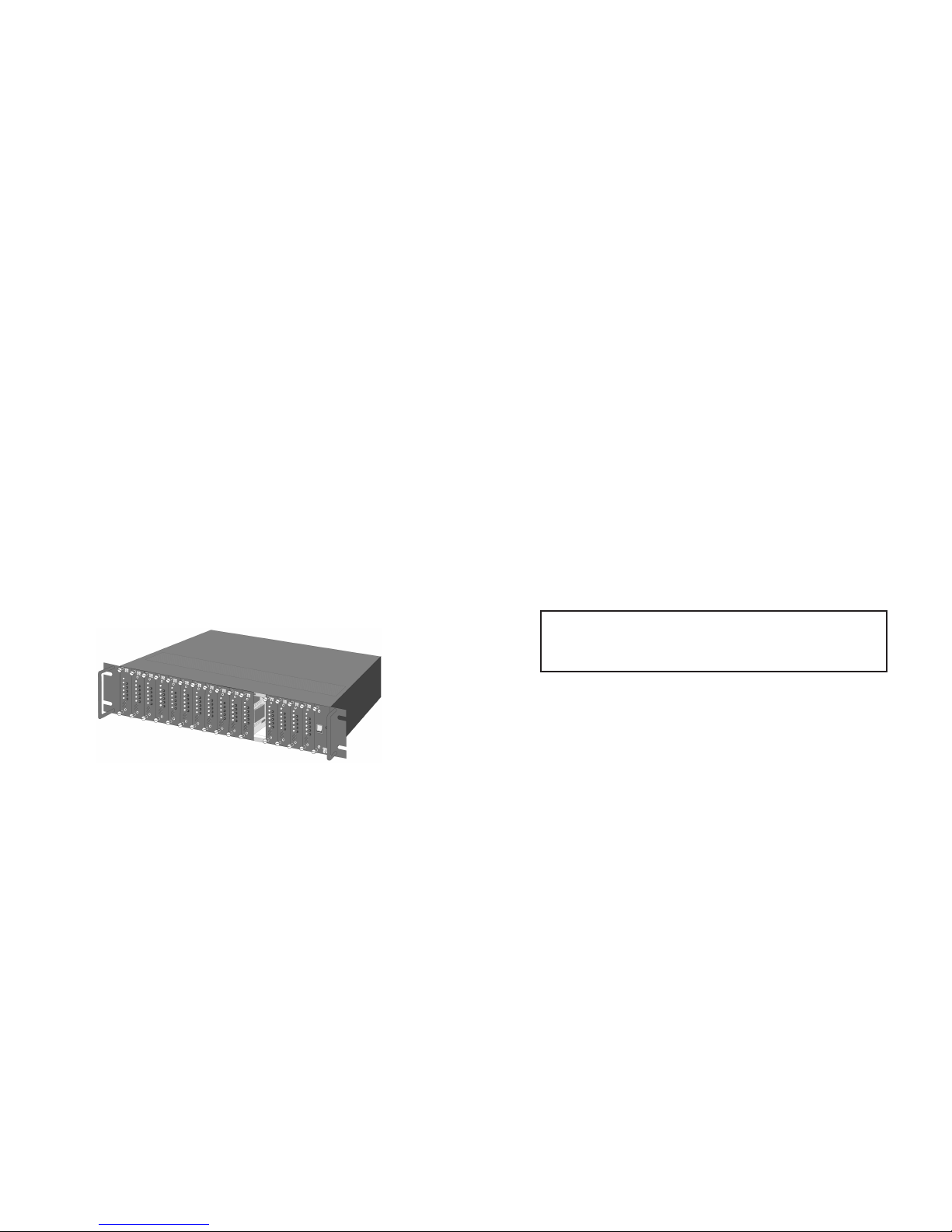
5.1 The 1001RP16P Rack Chassis
5.2 Installing the Power Supply Modules
5.3 Configuring the Rear Power Entry Card Alarm Operation
5.4 Installing the Rear Power Entry Cards
5.5 Installing the Front Power Cards (Initial Installation)
5.6 Making the Alarm Relay Connections
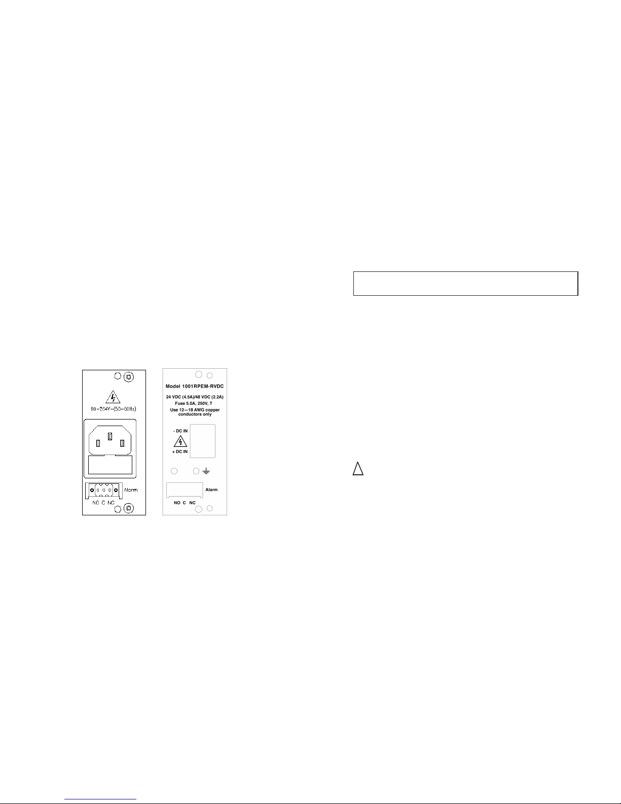
5.7 Connecting a 1001RPEM-RAC Entry Card to the AC
Voltage Source (90-264 VAC, 50-60 Hz)
5.8 Connecting a 1001RPEM-RVDC Entry Card to the 48 VDC
Source (42-62 VDC)
5.9 Service Procedure - Replacing a 1001RPSM-RUI Front Card
5.10Service Procedure - Replacing a 1001RPSM-R48V Front
Card
6.0 Operation.............................................................................15
6.1 LED Status Monitors
Appendix A - 48VDC Power Supply Specifications....................16
Appendix B - Universal AC Input Power Supply Specifications..19
Appendix C - Replacement Parts and Accessories ...................22
Appendix D - Safety Agency.......................................................23
1.0 WARRANTY INFORMATION
Patton Electronics warrants all Model 1001RP Series components to
be free from defects, and will—at our option—repair or replace the
products should they fail within one year from the first date of ship-
ment. This warranty is limited to defects in workmanship or materials,
and does not cover customer damage, abuse or unauthorized modifi-
cation. If these products fail or do not perform as warranted, your sole
recourse shall be repair or replacement as described above. Under no
condition shall Patton Electronics be liable for any damages incurred
by the use of these products. These damages include, but are not lim-
ited to, the following: lost profits, lost savings and incidental or conse-
quential damages arising from the use of or inability to use this prod-
uct. Patton Electronics specifically disclaims all other warranties,
expressed or implied, and the installation or use of this product shall be
deemed an acceptance of these terms by the user.
1.1 RADIO AND TV INTERFERENCE
The Model 1001RP Series units generate and use radio frequency
energy, and if not installed and used properly—that is, in strict accor-
dance with the manufacturer's instructions—may cause interference to
radio and television reception. They have been tested and found to
comply with the limits for a Class A computing device in accordance
with the specifications in Subpart J of Part 15 of FCC rules, which are
designed to provide reasonable protection from such interference in a
commercial installation. However, there is no guarantee that interfer-
ence will not occur in a particular installation. If these products do
cause interference to radio or television reception, which can be deter-
mined by turning off the unit, the user is encouraged to try to correct
the interference by one or more of the following measures: moving the
computing equipment away from the receiver, re-orienting the receiving
antenna and/or plugging the receiving equipment into a different AC
outlet (such that the computing equipment and receiver are on different
branches).
1.2 CE NOTICE
The CE symbol on your Patton Electronics equipment indicates
that it is in compliance with the Electromagnetic Compatibility (EMC)
directive and the Low Voltage Directive (LVD) of the European Union.
A Certificate of Compliance is available by contacting Technical
Support.

3 4
1.3 SERVICE
All warranty and non-warranty repairs must be returned freight pre-
paid and insured to Patton Electronics. All returns must have a Return
Materials Authorization number on the outside of the shipping contain-
er. This number may be obtained from Patton Electronics Technical
Service at
Tel: (301) 975-1007
email: [email protected]
www: http://www.patton.com
Patton Electronics’ technical staff is also available to answer any
questions that might arise concerning the installation or use of your
Model 1001RP Series. Technical Service hours: 8AM to 5PM EST,
Monday through Friday.
2.0 GENERAL INFORMATION
Thank you for your purchase of these Patton Electronics products.
They have been thoroughly inspected and tested and are warranted for
One Year parts and labor. If any questions or problems arise during
installation or use of these products, please do not hesitate to contact
Patton Electronics Technical Support at (301) 975-1007.
2.1 FEATURES
• Low-Profile mid-plane architecture design
• Provides redundant DC power for Patton rack cards
• Compatible with most Patton rack cards.The few that are not
compatible are: 1000CC, 1000RC/222NRC, 1010ARC, 1018ARC,
1045RC, 1060RC, 1070RC, 1080ARC, 1110RC/1110ARC, and
1140RC
• Plugs into Patton Electronics Redundant Rack Chassis (Model
1001RP)
• Redundant supply serves up to 14 function cards
• Single supply serves up to 16 function cards
• Easily replaceable front and rear modules
• LED Indicators: 12V, Fail, and Temperature
2.2 DESCRIPTION
There are two 1001 series power supplies: (1) Model
1001RPEM-RVDC is a rear power entry card that is used in conjunc-
tion with Model 1001RPSM-R48V front power supply card, and (2)
Model 1001RPEM-RAC is a rear power entry card that is used in con-
junction with Model 1001RPSM-RUI front power supply card. Using
two Model 1001RP supply modules, system operations won’t crunch to
a standstill if one supply fails. The second supply simply takes over!
CSU/DSUs, Baseband modems, and G.703 modems plugged into a
Model 1001RP continue to operate as normal.
Full redundancy is provided using two front power supply modules
and two rear power entry modules. That’s only two slots in a Patton
1001RP chassis. The remaining 14 slots can provide high speed
G.703 access, router links or short haul modem hook-ups. When
redundancy is not required, a single power supply may be used to
power a full rack of 16 function cards.
NOTE: Packages received without an RMA number will not be
accepted.

5 6
3.0 SCOPE
This service manual covers the installation, servicing and operat-
ing instructions for the Patton Electronics Models 1001RPSM-RUI and
1001RPSM-R48V redundant, rack-mount power supply modules,
including the 1001RPEM-RAC and 1001RPEM-RVDC power entry
cards. The modules are part of the 1001RP series rack system.
3.1 DEFINITION OF SERVICE PERSONNEL
Qualified service personnel are defined as persons who have the
appropriate technical training and experience necessary to (A) perform
tasks in the SERVICE ACCESS AREA of the equipment, and (B) be
aware of the hazards to which they are exposed in performing a task,
and of measures to minimize the danger to themselves or other per-
sons.
4.0 SAFETY PRECAUTIONS AND OPERATING INSTRUCTIONS
To comply with the published safety standards, the following must
be observed when using or installing the power supply modules.
A. Hazardous voltages exist in the primary circuits of AC-input
power supplies. Beware of internal lethal voltages due to charged
capacitors even after the AC input is disconnected. A minimum of
3 minutes should be allowed after input power is disconnected
before servicing the AC power supply modules.
B. Normal operating temperature range is 0°C to + 50°C at full rated
output power. Derate linearly to 50% of full load from 50°C to
70°C.
C. All chassis ventilation holes and fan intake openings must remain
open and unobstructed.
D. The power supply modules are components of the 1001RP series
rack system. When installing the modules and making input con-
nections, the relevant safety standards e.g. IEC950/VDE 0805, UL
1950 and EN 60950 must be complied with.
E. For continued safe operation, the power supplies must be operat-
ed with the appropriate fuses installed. For the AC supply, the
fuse should only be replaced by a 3.0A, 250V, time delayed,
Bussmann type GMD-3A or Wickmann type 198-1300-0-00.
For the DC supply, the fuse should only be replaced by a 5.0A,
250V, time delayed, LittelFuse type 215 005 or Wickmann type
19181-063-FS.
F. The disconnection of the input line voltage is made by pulling the
mains plug (AC supply) or the disconnection of the DC source at
the rear power entry card (DC supply).
G. The earth wire must be connected only to the chassis earthing
points marked with the earth ground symbol.
H. In case of failure or malfunction, the power supplies must be
returned to Patton Electronics for servicing to ensure continued
compliance with all safety requirements
WARNING! - HighVoltage Service Access Area
The power entry cavities and power supply cards are part of a
Service Access Area. This is designated by the electric shock
symbol located on the front and rear panels. Only qualified
service personnel should be permitted to access, install,
remove, service or configure power supply modules.

7 8
5.0 INSTALLATION
The following sections describe in detail how to properly install the
power supply modules, configure the rear power entry card alarm oper-
ation, and describe the initial installation of the front power supply
cards. Also included in the following sections are descriptions on mak-
ing the alarm relay connections, connecting a 1001RPEM-RAC entry
card to the AC voltage source (90-264 VAC, 50-60 Hz), and connecting
a 1001RPEM-RVDC entry card to the 48 VDC source (42-60 VDC).
This section also contains information on replacing a 1001RPSM-RUI
and a 1001RPSM-R48V front card.
5.1 THE 1001R16P RACK CHASSIS
The 1001R16P chassis is compact in size. It occupies only 2U
(3.5") of vertical height in a 19" rack. Two sturdy front handles allow
the unit to be installed, extracted or transported easily. Two configura-
tions of the 1001R16P are available:
1. 1001R14P - redundant power supply system:
Two power supplies and up to fourteen (14) function cards.
2. 1001R16P - standard power supply system:
One power supply and up to sixteen (16) function cards.
There are two power supply options:
1. Universal AC input (90-264 volts, 50-60 Hz) power supply: The
complete supply consists of a 1001RPSM-RUI front power supply
card and 1001RPEM-RAC rear power entry card. These two
cards together comprise a universal AC input supply module,
henceforth referred to as "the AC power supply".
2. 48 volt DC input (42-60 volts) power supply: The complete supply
consists of a 1001RPSM-R48V front power supply card and
1001RPEM-RVDC rear power entry card. These two cards togeth-
er comprise a 48 VDC input supply module, henceforth referred to
as "the DC power supply".
A single 1001R16P rack system may be fitted with any combina-
tion of the above-listed power supplies. For redundant applications,
two supplies are required.
5.2 INSTALLING THE POWER SUPPLY MODULES
This section describes how to install rear and front power supply
cards into the chassis and how to make the necessary rear card con-
nections.
All rack-mount power supplies consist of two cards: the rear
power entry card and the front power supply module card. The cards
meet inside the rack chassis and plug into each other using multi-pin
connectors. Refer to the following sections to correctly install the
power supply cards into the 1001R16P chassis.
5.3 CONFIGURING THE REAR POWER ENTRY CARD ALARM
OPERATION
The 1001RPEM-RAC and 1001RPEM-RVDC rear entry cards con-
tain a PC board mounted jumper to allow the customization of the
alarm operation. The jumper is located adjacent to the blue 8-pin
power connector. With the jumper installed onto the two posts (default
position), the relay contacts will NOT indicate an alarm condition when
a front card is physically removed from the rack chassis. With the
jumper installed onto only ONE post (or removed), the relay contacts
will indicate an alarm condition if a front power supply card is removed
from the chassis (or is not properly seated). Before installing the rear
entry card, configure the jumper as required by the application.
Figure 1: Model 1001RP Rack Chassis
CAUTION! The power supply cards contain static-sensitive
circuitry. Failure to use proper ESD precautions during installa-
tion or removal may result in damage to the power supply cir-
cuits.

9 10
5.4 INSTALLING THE REAR POWER ENTRY CARDS
The power supply modules occupy the right-most slots on the rack
system (as viewed from the front). Refer to Figure 2 and follow the
instructions below to properly install the rear power entry cards into the
rack chassis. The rear entry cards must be in place and securely fas-
tened before the front cards can be installed.
To install a rear power entry card follow the steps below:
1. Attach the earth ground wire (green with yellow tracer) of the first
power entry card (slot #17) to the stud along the inside wall of the
chassis, as shown. The star washer should be between the chas-
sis and the ground lug. Securely tighten the retaining nut. Failure
to connect the earth ground wire may result in a hazardous condi-
tion.
2. Install the first power entry card into slot #17 in the rear of the
chassis. Secure the card using the two screws provided.
Steps 3-5 are for redundant applications only:
3. Attach the ground wire of the second power entry card to the bare
metal side of the rear spacer. The spacer has two ground studs
and is powder-coat finished on only one side. The star washer
should be installed between the spacer and the ground lug.
Securely tighten the retaining nut.
4. Secure the rear spacer to slot #16 using the two screws provided.
5. Install the second power entry card into slot #15. Secure the card
using the two screws provided.
5.5 INSTALLING THE FRONT POWER SUPPLY CARDS (INITIAL
INSTALLATION)
To install a new front power supply card into the chassis, follow the
instructions below:
1. Make sure that the associated rear power entry card is securely
installed into the rack chassis.
2. Install a new power supply front card by carefully aligning the card
with the chassis guides. Gently slide the card, along the metal
rails provided, into the front of the chassis. The card connectors
will meet the mid-plane bus when the card is almost all the way
into the chassis.
3. After the connectors meet, gently apply even pressure to the top
and bottom of the panel to seat the card. Do not force the card
into the chassis. This may damage the connector pins.
4. Use a flat blade screwdriver to tighten the captive screws.
5. Repeat steps 1-4 for the second power supply card (redundant
applications only).
6. Secure the front spacer to slot #16 using the two screws provided
(redundant applications only).
1001R16P/R8V Chassis
Ground Stud
Slot #17
Slot #16
Slot #15
Ground Wire
Ground Wire
Spacer
Model 1001RP
Rear Card
Model 1001RP
Rear Card
Figure 2: Model 1001RP Rack Chassis, Showing Rear Card Installation
Warning! To avoid electric shock, never install or service
any rear power entry card while the input voltage source is
connected.

11 12
5.6 MAKING THE ALARM RELAY CONNECTIONS
The 1001RPEM-RAC and 1001RPEM-RVDC rear power entry
cards (figure 3, below) feature a 3-position, screw-type terminal plug for
the alarm connections. Both normally-open (NO) and normally-closed
(NC) relay contacts are provided. Choose the appropriate set of con-
tacts for the intended application. The NO contacts are open for nor-
mal operating conditions and close when a fault condition occurs (loss
of module input power, overheating or module failure). The NC con-
tacts are closed under normal operating conditions.
“NO” Contacts: The “NO” (normally-open) contacts are open for normal
operating conditions and close when a fault condition
occurs (loss of input power, overheating or module failure).
“NC” Contacts: The “NC” (normally-closed) contacts are closed for normal
operating conditions.
The alarm terminal plug accepts 12-26 AWG size wire, solid or
stranded. For ease of hookup, the terminal plug can be removed from
the rear panel alarm port by loosening the two securing screws. After
connections to the plug have been made, insert the plug back into the
alarm port on the rear panel and tighten the securing screws.
Spare terminal plugs may be obtained directly from Patton
Electronics. See Appendix for part numbers, contact ratings and gen-
eral alarm port specifications.
5.7 CONNECTING A 1001RPEM-RAC ENTRY CARDTO THE AC
VOLTAGE SOURCE (90-264 VAC, 50-60 Hz)
For the AC main connection, the 1001RPEM-RAC is equipped with
a shrouded male IEC-320 compatible power entry connector. This con-
nector contains an integral fuse and accepts a domestic US power
cord or any of several international AC power cords. Only three-wire
power cords containing an earth ground lead may be used. After the
power cord is properly connected and power is applied, the green
"12V" LED on the 1001RPSM-RUI front panel will be illuminated and
the fan will operate. Voltage selection is automatic. There is no on/off
switch.
5.8 CONNECTING A 1001RPEM-RVDC ENTRY CARD TOTHE 48
VDC SOURCE (42-60 VDC)
For the 48 VDC connection, the 1001RPEM-RVDC is equipped
with a three-position, clamp-style terminal block. Only the two outer-
most terminals are used. In addition to the terminal block, an external
lug is provided for the connection of earth ground. Follow the steps
below to make the DC power connections:
CAUTION: Use copper conductors between 12 - 18 AWG only
1. Connect the earth ground of the DC source to the exterior lug on
the entry card using the hardware provided. The earthing conduc-
tor must be equivalent to or larger than the conductors used for
the input supply connections.
2. Strip back the insulation on each of the wires approximately ¼
inch.
3. Use a small flat-blade screwdriver to open the cage clamp of the
terminal block. Insert the stripped end of the positive lead into the
"+DC input" of the terminal block and remove the screwdriver.
Repeat the procedure for the negative lead, using the "-DC input"
of the terminal block. Make sure that all strands of wire are cap-
tured and that there is no exposed wire.
WARNING! 1001RPEM-RAC power entry cards are to be
used
ONLY
with three wire grounded outlets.
Figure 3. Models 1001RPEM-RAC & 1001RPEM-RVDC rear panel
Rear Panel
1001RPEM-RAC Rear Panel
1001RPEM-RVDC
!

13 14
After the DC power supply leads are properly connected and
power is applied, the green "12V" LED on the 1001RPSM-R48V front
panel will be illuminated and the fan will operate. There is no on/off
switch.
5.9 SERVICE PROCEDURE - REPLACING A 1001RPSM-RUI
FRONT CARD
This section describes the procedure for replacing an already-
installed 1001RPSM-RUI AC power supply front card. A flat blade
screwdriver is required to remove and install the card.
To replace an already-installed 1001RPSM-RUI AC power supply
front card, follow the detailed instructions below:
1. Loosen the two front-panel captive securing screws. Do not
remove the screws from the card.
2. Using two hands, grasp the captive screws and slowly separate
the card from the rack until the front panel is approximately ONE
INCH from the edge of the rack chassis. This disconnects the
front card from the AC voltage source.
DO NOT COMPLETELY
REMOVE THE CARD FROM THE RACK CHASSIS!
3. After a minimum of three minutes have elapsed after disconnect-
ing the AC voltage source, the front card may be safely removed
from the rack chassis.
4. Install a new 1001RPSM-RUI front module by carefully aligning it
with the chassis guides. Gently slide the card into the chassis
along the metal rails provided. The card connectors will meet the
mid-plane bus when the card is almost all the way into the chassis.
5. After the connectors meet, gently apply even pressure to the top
and bottom of the panel to seat the card. Do not force the card
into the chassis. This may damage the connector pins.
6. Tighten the captive screws. The green "12V" LED should be illu-
minated and the fan should operate.
5.10 SERVICE PROCEDURE - REPLACING A 1001RPSM-R48V
FRONT CARD
Follow the same procedure as outlined in the section "REPLAC-
ING A 1001RPSM-RUI FRONT CARD". Since the 1001RPSM-R48V
uses only non-hazardous, low DC voltage, it may be safely removed
from the rack chassis immediately after loosening the captive screws.
WARNING! Hazardous voltages exist in the primary cir-
cuits. Beware of internal lethal voltages due to charged capaci-
tors even after the AC input is disconnected. A minimum of 3
minutes should be allowed after AC input power is disconnect-
ed before removing or handling the front power supply module.
WARNING! Hazardous voltages present. To avoid electric
shock or personal injury, adhere to the module replacement
instructions exactly as stated.

15 16
6.0 OPERATION
Once the Model 1001RP Series power supply module is properly
installed, you are ready to operate the unit. Figure 4 (below) shows the
location of LED indicators.
6.1 LED STATUS MONITORS
The power supply modules features three LEDs on the front panel
that indicate the status of the unit.The following describes the LED sta-
tus monitors.
12V Green LED lights when the module is operating normally and
is supplying 12 VDC to the rack mid-plane.
FAIL Red LED lights when the module fails, overheats or input
power is lost.
TEMP Red LED lights when maximum module operating tempera-
ture has been exceeded, due to fan failure, overload or
extremely high ambient temperature. During an over tempera-
ture condition, module output power is drastically reduced.
After the module has sufficiently cooled, normal operation is
restored.
APPENDIX A
PATTON ELECTRONICS MODELS 1001RPSM-R48V plus
1001RPEM-RVDC, 48VDC SPECIFICATIONS
12V FAIL
TEMP
Figure 4: Models 1001RPSM-R48V & 1001RPSM-RUI Front Panel, Showing LED’s
Input Specifications
PARAMETER CONDITIONS/DESCRIPTION MIN NOM MAX UNITS
Input Voltage - DC Reverse polarity protected. 42 48 60 VDC
Brown out Protection Lowest DC input voltage that 36 VDC
regulation is maintained with
full rated load.
Input Current 42 VDC, 72W load 2.2 A
Input Protection User-replaceable, internally
located DC Input line fuse
Input Surge TVS 75 VDC
Suppression
Output Specifications
PARAMETER CONDITIONS/DESCRIPTION MIN NOM MAX UNITS
Output Voltage Output voltage to midplane 12.3 12.4 12.5 VDC
bus. (75% load).
Output Power Continuous output power. 72 Watts
Turn-on Delay Time required for initial 3 Sec
output stabilization.
Turn-on Rise Time Time required for output voltage 1 Sec
to rise from 10% to 90%.
Transient Response Recovery time to within 1% of 250 us
initial set point due to a 30-100%
load change.
Load Sharing Two Supplies, 72W load. 1 5 %
Accuracy
Efficiency Full load, 48VDC in. 78 88 %

17 18
APPENDIX A
(continued)
PATTON ELECTRONICS MODELS 1001RPSM-R48V plus
1001RPEM-RVDC, 48VDC SPECIFICATIONS
APPENDIX A
(continued)
PATTON ELECTRONICS MODELS 1001RPSM-R48V plus
1001RPEM-RVDC, 48VDC SPECIFICATIONS
Interface Signals and Internal Protection
PARAMETER CONDITIONS/DESCRIPTION MIN NOM MAX UNITS
Indicators GREEN indicator for normal
operating mode.
RED indicators for power fail
and excessive internal temperatures.
Power Fail Warning Logic LOW to 1000MC control card 0.7 VDC
(TTL compatible) (denotes power fail detected).
Logic HIGH with internal pull-up 10 k ohm
to output.
Output low voltage trip point. 11.6 11.8 12.0 VDC
Power fail trip point, maximum 30 36 38 VDC
load, decreasing input.
Time before regulation dropout, 200 us
full load, due to loss of input power.
Alarm Contacts Normally-open and normally closed
contacts via 3-position terminal block
(1A@30V). Contacts operate upon
power failure detection.
Overtemperature RED indicator.Shifts power fail
Indication signal to a logic LOW state.
Output voltage during 4 4.5 5 VDC
overtemperture condition
User Controls Single jumper to select
“maintenance mode.” (No alarm
if PS is removed).
Safety, Regulatory and EMI Specifications
PARAMETER CONDITIONS/DESCRIPTION MIN NOM MAX UNITS
Agency Approvals NRTL US UL/1950, CAN CSA/950
EN60950 Recognized
CE Mark
FCC Part 15, Class A
Dielectric Withstand Input to output, 1 second 3000 VRMS
Voltage Input to chassis, 1 second 1500 VRMS
Safety, Regulatory and EMI Specifications
PARAMETER CONDITIONS/DESCRIPTION MIN NOM MAX UNITS
Operating At 100% load. 0 50 °C
Temperature Derate linearly above At 50% load. 70 °C
50°C by 2.5% per °C.
Storage Temperature -40 85 °C
Relative Humidity Non-condensing 90 %RH
Weight 0.7 lbs.

19 20
APPENDIX B
PATTON ELECTRONICS MODEL 1001RPSM-RUI plus
1001RPEM-RAC, UNIVERSAL AC INPUT SPECIFICATIONS
APPENDIX B
(continued)
PATTON ELECTRONICS MODEL 1001RPSM-RUI plus
1001RPEM-RAC, UNIVERSAL AC INPUT SPECIFICATIONS
Input Specifications
PARAMETER CONDITIONS/DESCRIPTION MIN NOM MAX UNITS
Input Voltage - AC Universal input, Auto ranging. 90 115/230 264 VAC
Input Frequency AC Input. 47 63 Hz
Brown Out Lowest AC input voltage 90 VAC
Protection that regulation is maintained
with full rated load.
Hold-up Time Nominal AC input voltage. 72W load. 15 ms
36W load. 30 ms
Input Current 90 VAC, 72W load. 1.8 ARMS
Input Protection User-replaceable, externally located
AC input line fuse.
Inrush Surge Internally limited by thermistor. 38 APK
Current Vin = 264 VAC (one cycle) 25°C.
Input Surge Line-to line via MOV 300 VAC
Suppression
Output Specifications
PARAMETER CONDITIONS/DESCRIPTION MIN NOM MAX UNITS
Output Voltage Output voltage to midplane 12.3 12.4 12.5 VDC
bus. (75% load).
Output Power Continuous output power. 72 Watts
Turn-on Delay Time required for initial 3 Sec
output stabilization.
Turn-on Rise Time Time required for output voltage 1 Sec
to rise from 10% to 90%.
Transient Response Recovery time to within 1% of 250 us
initial set point due to a 30-100%
load change.
Load Sharing Two Supplies, 72W load. 1 5 %
Accuracy
Efficiency Full load, 115VAC in. 78 88 %
Safety, Regulatory and EMI Specifications
PARAMETER CONDITIONS/DESCRIPTION MIN NOM MAX UNITS
Agency Approvals NRTL US UL/1950, CAN CSA/950
EN60950 Recognized
CE Listing
FCC Part 15, Class A
Dielectric Withstand Input to output, 1 second 3000 VRMS
Voltage Input to chassis, 1 second 1500 VRMS
Leakage Current 264 VAC 1 mA
Interface Signals and Internal Protection
PARAMETER CONDITIONS/DESCRIPTION MIN NOM MAX UNITS
Indicators GREEN indicator for normal
operating mode.
RED indicators for power fail
and excessive internal temperatures.
Power Fail Warning Logic LOW to 1000MC control card 0.7 VDC
(TTL compatible) (denotes power fail detected).
Logic HIGH with internal pull-up 10 k ohm
to out-put.
Output low voltage trip point. 11.6 11.8 12.0 VDC
Power fail trip point, maximum 85 90 94 VAC
load, decreasing input.
Time before regulation dropout, 5 ms
full load, due to loss of input power.
Alarm Contacts Normally-open and normally closed
contacts via 3-position terminal block
(1A@30V). Contacts operate upon
power failure detection.
Overtemperature RED indicator.Shifts power fail
Indication signal to a logic LOW state.
Output voltage during 4 4.5 5 VDC
overtemperture condition
User Controls Single jumper to select
“maintenance mode.” (No alarm
if PS is removed).

21 22
APPENDIX B
(continued)
PATTON ELECTRONICS MODEL 1001RPSM-RUI plus
1001RPEM-RAC, UNIVERSAL AC INPUT SPECIFICATIONS
APPENDIX C
PATTON MODEL 1001RP FACTORY REPLACEMENT
PARTS AND ACCESSORIES
Patton Model # Description
1001RPSM-R48V............Redundant 48-VDC Front Power Supply
Module
1001RPSM-RUI ..............Redundant Universal AC Input Front
Power Supply Module
1001RPEM-RVDC...........Redundant 48VDC Input Rear Power
Entry Module
1001RPEM-RAC.............Redundant Universal AC Input Power
Entry Module
1001R14P .......................2U 14 Slot Redundant Rack Chassis
05R16FP440W................Front Spacer
05R16BP440W................Rear Spacer
08246 ..............................3A fuse (Bussman GMD-3A, Wickman
198-1300-0-00)
08246-2 ..........................5A fuse (Littelfuse 215 005, Wickman
19181-063-FS)
10-00003 ........................Terminal Plug For Alarm Connection
07M1001RPR..................User Manual
07M1001RPSVC ............Service Manual
05R16PL ........................Plenum
Safety, Regulatory and EMI Specifications
PARAMETER CONDITIONS/DESCRIPTION MIN NOM MAX UNITS
Operating At 100% load. 0 50 °C
Temperature Derate linearly above At 50% load. 70 °C
50°C by 2.5% per °C.
Storage Temperature -40 85 °C
Relative Humidity Non-condensing 90 %RH
Weight 0.7 lbs.

APPENDIX D
Safety Agency Recognition
Plenum Installation
Compliance with NRTL/UL 1950/EN60950
Safety agency regulations require the use of an approved plenum
(Patton part number (05R16PL) with each 1001R rack installation.
A rack chassis fitted with the plenum constitutes an agency recog-
nized fire enclosure. All 1001R rack installations require at least
one plenum to be fitted underneath the bottom-most chassis in the
system for continued compliance with agency regulations.
Thermal Management
Due to the small size and high performance of the 1001R rack
system, a fully-loaded rack chassis may generate a considerable
amount of heat. To ensure long equipment life, it is important the
thermal management guidelines are adhered to in all 1001R
installations. In high density, stacked configurations, additional
plenums may be required between each chassis to improve sys-
tem thermal performance. Ambient air temperature, total rack
power dissipation and the number of stacked units must all be
considered when determining cooling requirements. For further
information, see the application note “Thermal Management
Guidelines for the 1001R Rack System”, available on Patton’s
website at www.patton.com.
Copyright © 1999
Patton Electronics Company
All Rights Reserved
Table of contents
Other Patton electronics Power Supply manuals