Pauli + Sohn Sword User manual

Montagean eitung „Schwert“
Assembly instructions “Sword”
386_Mont_Schwert_P_S_386_Mont_Schwert_001.qxd 21.04.10 11:44 Seite 1
2/3
Montagean eitung „Schwert“
Assembly instructions “Sword”
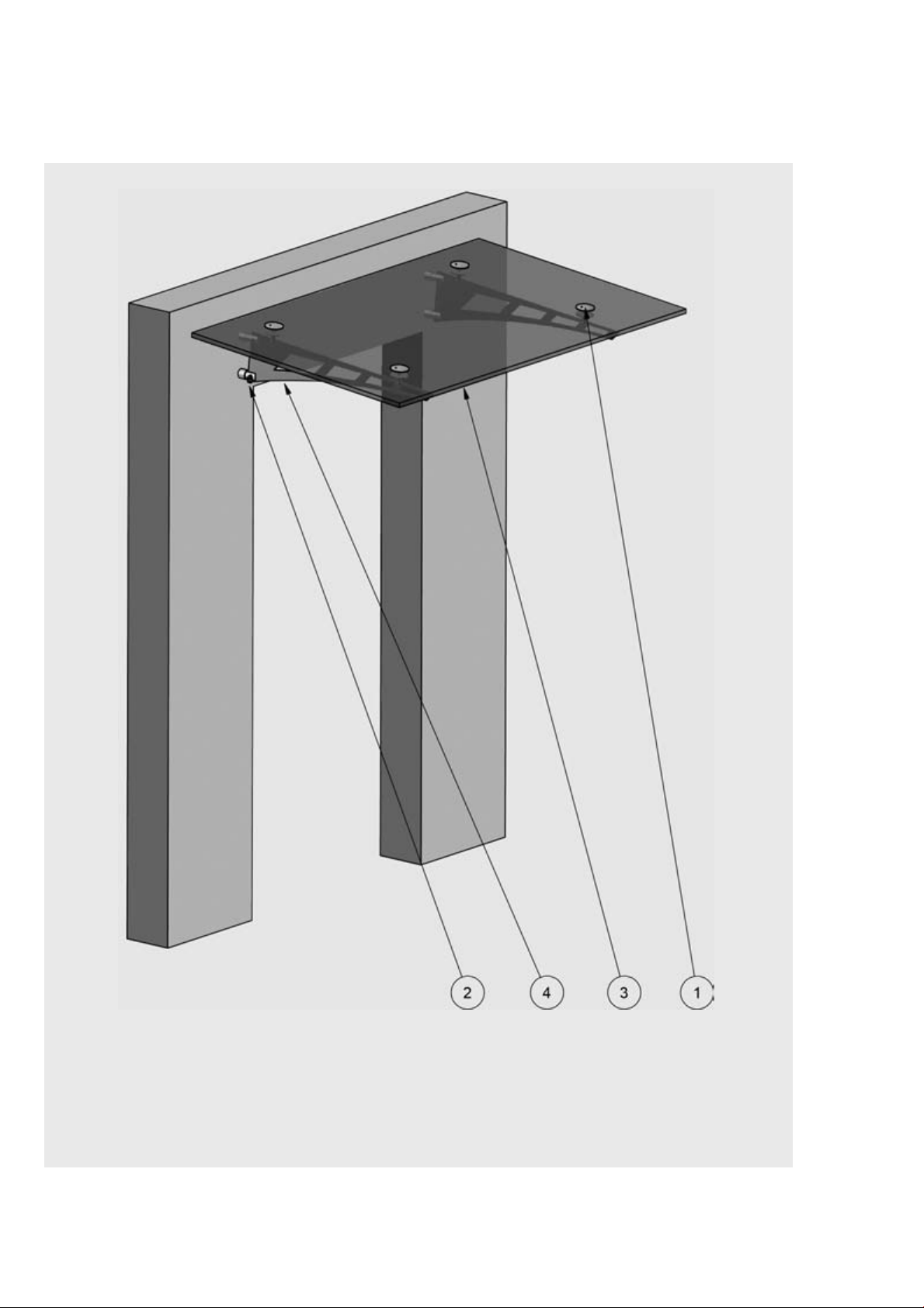
Position Artikel-Nr. Bezeichnung
Position Arti le no. Arti le name
1 1927va Glasplattenhalter(Gabel) für VSG16/Glass panel mount (fork) for LSG 16
2 1705va Verstellbare Wandgabelbefestigung für Auslegervordach/
Adjustable wall mount for a anopy with arrying support
3 VSG16 VSG 16 aus 2x TVG 8mm PVB-Folie 1,52mm/
LSG 16 made of 2x HSG 8mm PVB-laminate 1,52mm
4 1706-1va Ausleger (Schwert)/Carrying support (sword)
Tipps zur Reinigung und Pf ege von Ede stah f ächen finden Sie unter www.pau i.de
For instructions and recommendations for cleaning and handling of stainless steel surfaces click under: www.pauli.de
386_Mont_Schwert_P_S_386_Mont_Schwert_001.qxd 21.04.10 11:44 Seite 2
Montagean eitung „Schwert“
Assembly instructions “Sword”
Position Artikel-Nr. Bezeichnung
Position Arti le no. Arti le name
2 1705va Verstellbare Wandgabelbefestigung für Auslegervordach/
Adjustable wall mount for a anopy with arrying support
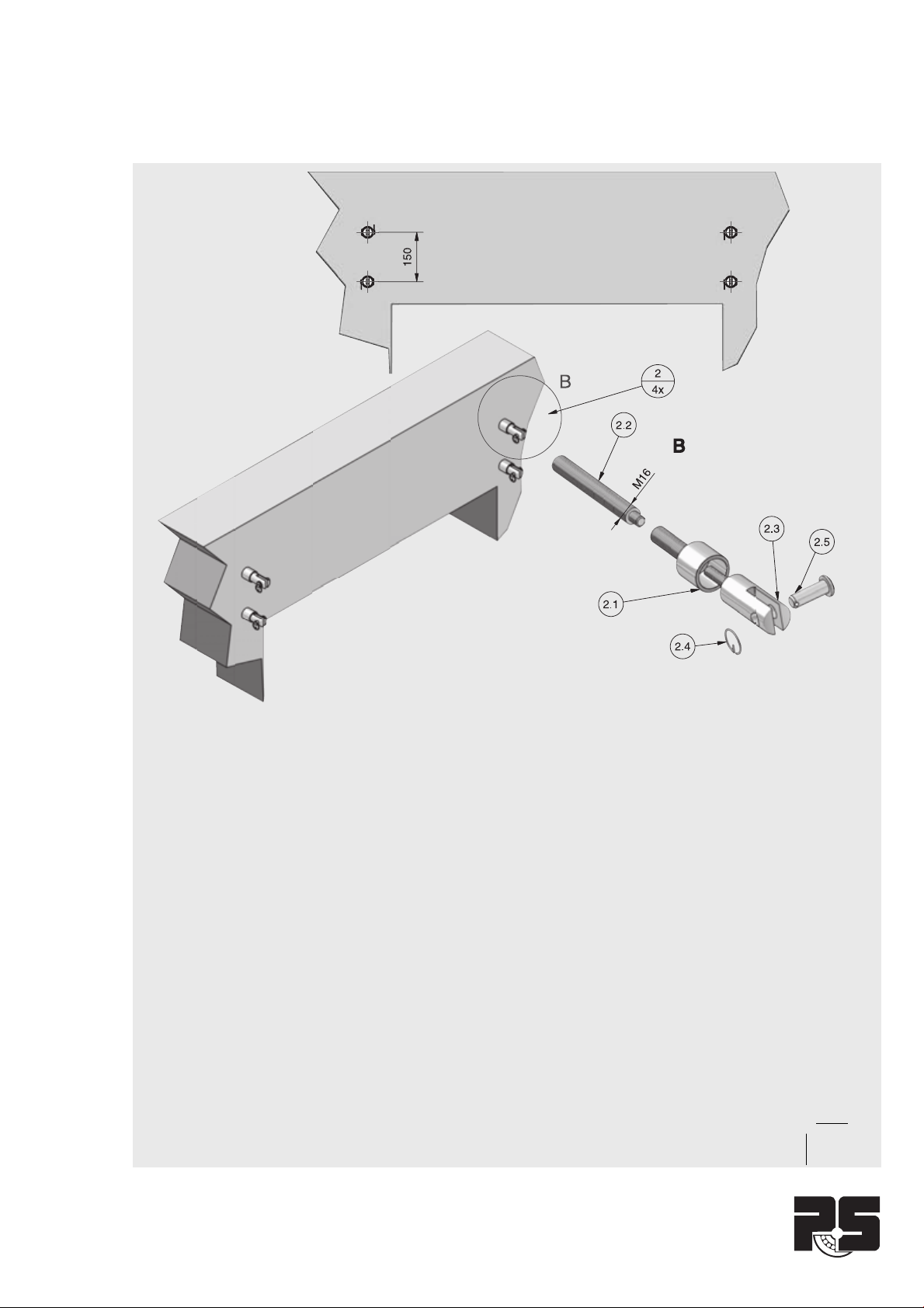
2.1 1705-2va Befestigungshülse zu 1705va/Fastening part for 1705VA
2.2 1705-4va Gewindestange zu 1705va/Threaded stud for 1705VA
2.3 1705-1va Gabel zu 1705va/Fork for 1705VA
2.4 1821-6va Ringsplint/Se urity ring
2.5 1705-3va Steckbolzen/Stud
Wandbefestigung montieren (Einsteckmontage)
Zunächst zeichnen Sie die Bohrpunkte für die oberen und unteren
Wandbefestigungen (1705va) an und bohren die entsprechenden
Löcher in die Wand.
Werden Siebhülsen für Loch- oder Kammersteine eingesetzt,
müssen die Bohrlöcher sauber ausgeblasen werden, um einen
optimalen Halt der Klebeverbindung gewährleisten zu können.
Bitte auf Herste erhinweise achten.
Denken Sie daran, die Befestigungshülse (1705-2va) mit Gewin-
destange (1705-4va) gleich nach dem Einschieben vertikal als
auch horizontal zu justieren. Nach der
vorgeschriebenen Aushärtezeit können Sie die Gabeln (1705-1va)
in die Befestigungshülse (1705-2va) eindrehen.
Assemble the wall mounts (Assembly by insertion)
First mark the drilling points for the upper and lower wall moun-
tings (1705VA), and then drill the holes a ordingly.
If sieves for perforated masonry or arity bri ks are used, the bore-
holes must be leaned thouroughly to ensure max. holding apabi-
lity on the bond.
Please pay attention to the references of the manufacturer.
Make sure to adjust the fastening part (1705-2VA) with the threa-
ded stud (1705-4VA )so they are level and at the right length.
After waiting the pres ribed hardening time, you an s rew the
forks (1705-1VA) into the fastening part (1705-2VA)
386_Mont_Schwert_P_S_386_Mont_Schwert_001.qxd 21.04.10 11:44 Seite 3
4/5
Montagean eitung „Schwert“
Assembly instructions “Sword”
Position Artikel-Nr. Bezeichnung
Position Arti le no. Arti le name
2 1705va Verstellbare Wandgabelbefestigung für Auslegervordach
Adjustable wall mount for a anopy with arrying Support
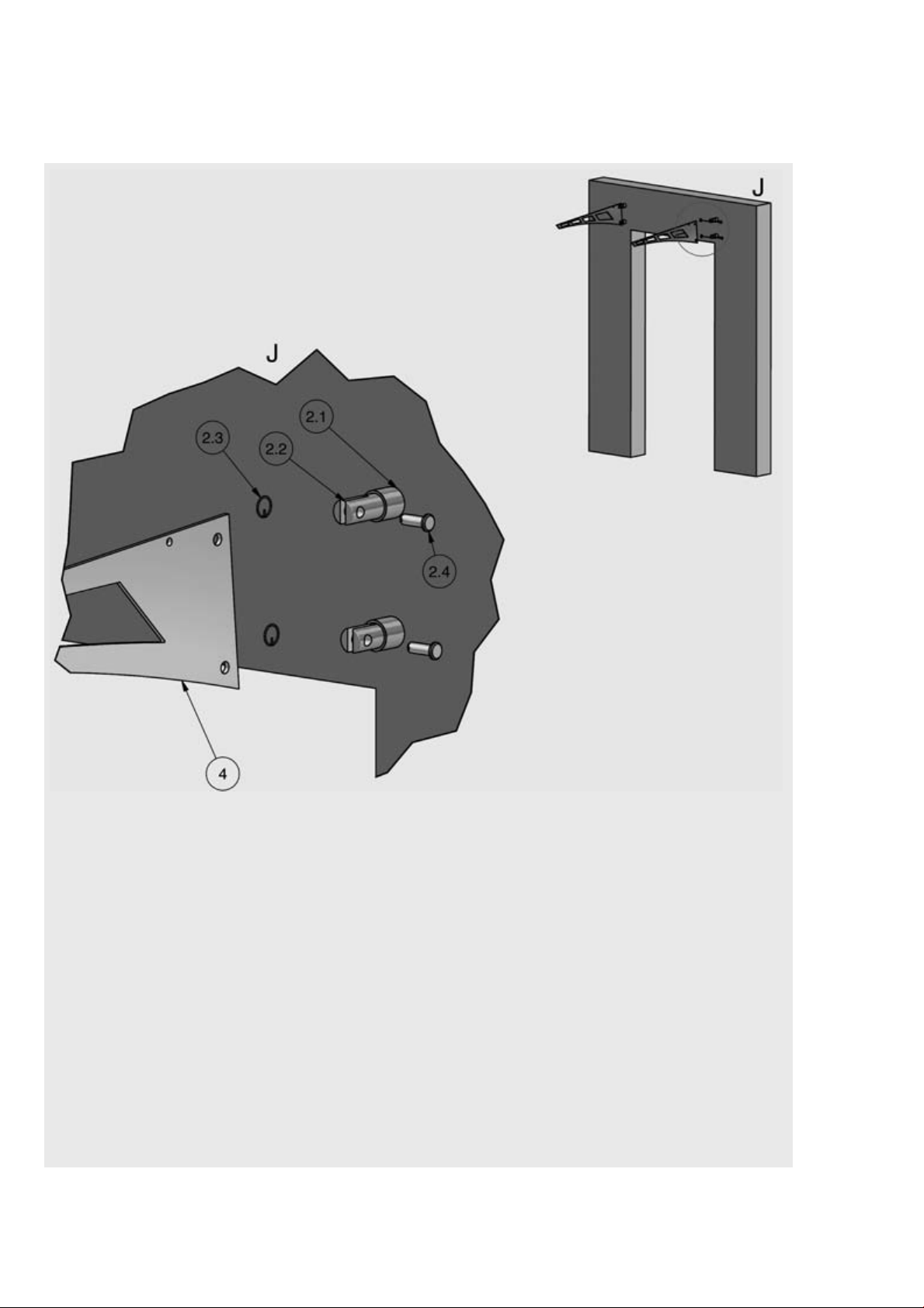
2.1 1705-2va Befestigungshülse zu 1705va/Fastening part for 1705VA
2.2 1705-1va Gabel zu 1705va/Fork for 1705VA
2.3 1821-6va Ringsplint/Se urity ring
2.4 1705-3va Steckbolzen/Stud
4 1706-1va Ausleger (Schwert)/Carrying support (sword)
Montage der Aus eger
Alle Verbindungen erfolgen durch Gabel und Öse.
Schieben Sie die Ausleger (1706-1va) in die Gabel (1705-1va)
und sichern diese mit den Steckbolzen (1705-3va) und Rings-
plint (1821-6va). Die Gabel (1705-1va) müssen entsprechend
der vorgesehenen Dachneigung justiert werden (siehe Seite 7).
Assembly of the carrying Support
All onne tions are made by fork and eye links.
Insert the arrying support (1706-1VA) into the fork (1705-1VA)
and se ure it with the stud (1705-3VA) and the se urity ring
(1821-6VA). The forks (1705-1VA) must be adjusted according
to the slope angle table (see page 7).
386_Mont_Schwert_P_S_386_Mont_Schwert_001.qxd 21.04.10 11:44 Seite 4

Montagean eitung „Schwert“
Assembly instructions “Sword”
Befestigen Sie die G asp attenha ter
(1927VA) am Glas. Diese müssen in der gleichen Reihenfolge,
wie die Abbildung zeigt, zusammengebaut werden.
Zwischen Glas und etall muss immer ein Weich-PVC
montiert werden. Achten Sie auch unbedingt auf die richtige
Ausrichtung der Gabelköpfe (90° zur Wand) und ein
Anzugsmoment von 16 N •m.
Attach the fittings
(1927VA) to the glass. These must be mounted in the
same order
as shown on page 3. A PVC-washer must always be mounted
between glass and metal. Pay lose attention to an exa t
positioning of the fork heads (90° to the wall) and to having a
tightening torque of 16 N •m.
Position Artikel-Nr. Bezeichnung
Position Arti le no. Arti le name
1 1927va Glasplattenhalter(Gabel) für VSG16/Glass panel mount (fork) for LSG 16
PVC-Scheibe/
PVC-washer
Hülse/
Sleeve
Bohrung/
Bore
PVC-Scheibe/
PVC-washer
K
K
386_Mont_Schwert_P_S_386_Mont_Schwert_001.qxd 21.04.10 11:44 Seite 5
6/7
Montagean eitung „Schwert“
Assembly instructions “Sword”
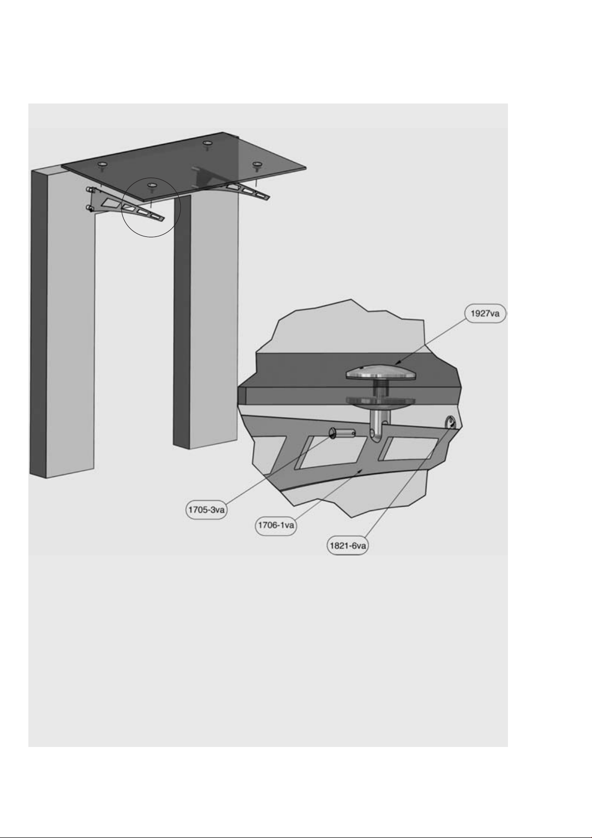
Montage der G asscheibe
Die Glasscheibe mit den montierten Glashaltern (1927VA)
kann nun von oben mit den Auslegern 1706-1va mittels der
Steckbolzen (1705-3va) verbunden werden und anschließend
mit dem Ringsplint (1821-6va) gesichert werden.
Assembly of the glass panel
The glass panel with the assembled glass panel mounts (1927VA)
an now be onne ted to the arrying supports 1706-1VA from
above with the studs (1705-3VA) and afterwards must be
se ured with the se urity ring (1821-6VA).
L
386_Mont_Schwert_P_S_386_Mont_Schwert_001.qxd 21.04.10 11:44 Seite 6

Montagean eitung „Schwert“
Assembly instructions “Sword”
R
Dachneigung + I slope +
Maß A | dimension A 42 47 52 57 62 67
Maß B | dimension B 42 42 42 42 42 42
Maß h | dimension h 150 150 150 150 149 148
Maß w | dimension w 10 10 10 10 10 10
αDachneigung | slope 0° 2° 4° 6° 8° 10°
Maß C (Ausladung) | dimension C (outspann) 1003 1010 1017 1024 1031 1038
Maß D (Randabstand) | dimension D (edge distance) 133 140 147 154 161 168
Dachneigung - I slope -
Maß A | dimension A 42 42 42 42 42 42
Maß B | dimension B 42 47 52 57 62 67
Maß h | dimension h 150 150 150 150 149 148
Maß w | dimension w 10 10 10 10 10 10
αDachneigung | slope 0° 2° 4° 6° 8° 10°
Maß C (Glastiefe) | dimension C (glass width) 1003 1001 998 996 994 992
Maß D (Randabstand) | dimension D (edge distance) 133 131 128 126 124 122
M
Maß | dimension D
Randabstand hinten | backward edge distance
620
250
300
Ø 18
Ø 18
300
max. 2000 mm für 4 Punkthalter
max. 2000 mm for 4 point fixings
Maß | dimension C
620
250
30 00
max. 3000 mm für 6 Punkthalter
max. 3000 mm for 6 point fixings
Maß | dimension C
Dachneigung
±10°
slope ± 10°
Maß (42 - 67)
dimension
Maß (42 - 67)
dimension
177
120
andere Längen auf Anfrage/
other lengths are available on request
Maß
h
dimension
R
386_Mont_Schwert_P_S_386_Mont_Schwert_001.qxd 21.04.10 11:44 Seite 7

Art.-Nr. P8520 Stand: September 2005
Die Angaben basieren auf dem derzeitigem Stand der Technik. Änderungen sind uns vorbehalten.
Werk I: Eisenstraße 2, D-51545 Waldbröl, Telefon +49 (0) 2291/92 06-0, Telefax +49 (0) 22 91/9206-681
Werk II: Industriestraße 20, D-51597 orsbach, Telefon +49 (0) 22 94/98 03-0, Telefax +49 (0) 22 94/98 03-881
Internet: www.pauli.de; e-Mail: [email protected]
386_Mont_Schwert_P_S_386_Mont_Schwert_001.qxd 21.04.10 11:44 Seite 8


