Pavone Sistemi 1008 User manual

Pavone Sistemi
pesatura elettronica industriale
Pavone Sistemi
pesatura elettronica industriale
USER MANUAL
TESTER 1008 for checking simultaneously a weighing system with up to 4 load cells
Calibrator and mV/V signal simulator
Software version P28901

Page II

Rel ID 170504 SW 0.4
Page 1
INDEX
Technical Specifications ............................................................................... Page 2
Connection Sub-D 25 poles.......................................................................... Page 3
Tester: Switch ON ....................................................................................... Page 4
Signal Detection.......................................................................................... Page 5
Tester Functions........................................................................................... Page 6
Display ...................................................................................................... Page 7
Tester Functions........................................................................................... Page 8
Tester Functions: Autotare............................................................................. Page 10
Tester: Calibrator Functions........................................................................... Page 11-12
Main Menu ................................................................................................ Page 13-14
Instrument Files Menu .................................................................................. Page 15
Configuration Files Menu ............................................................................. Page 16
NFC Communication Files............................................................................ Page 17
Management from PC.................................................................................. Page 18
Example: Configuration Files ........................................................................ Page 18

Page 2
TECHNICAL SPECIFICATIONS
Power Supply: 4 x 1,5V Alkaline Batteries or NiMh 1.2V
rechargeables
Consuption: Max. 170 mA (Max. Light, 4 load cells of 350 Ohm)
Operating Temperature: -10°C ÷ +50°C
Storage Temperature: -20°C ÷ +70°C
Display: LCD graphic monochrom. 4” (240 x 128 pixels)
Keyboard: Touch panel + Swtich On button
Dimensions: 185 x 93 x 36 mm (H x L x D)
Case: Palm- ABS
Protection Degree: IP54
Load cells Conncetion: Sub-D 25 poles cable
4 indipendent channels:
Load Cells Excitation: 3.3 Vdc / 50 mA (max 4 load cells of 350 Ohm)
Internal Resolution: 24 bit
Weight Display: Up to 50.000 divisions
Input Signal: From -3.9 to 3.9 mV/V
Load Cells Impedence: From 350 Ohm to 2000 Ohm
Calibrator Specifications: For equipment with load cells excitation from +/-3Vdc
up to +/-15 Vdc with input resistance >100 kohm.
Output Signal: -3 mV /+20.3 mV (Optional +30mV)
Resolution: 16 bit
Output: Panel Touch
Linearity: < 0,02% FS
Temperature Drift: 0,001% FS / °C
Communication Ports: N° 1 USB device (connection to a PC)
N° 1 RS232 (connection to instrument)
N° 1 NFC (connection to DAT1400)
Status Battery: Battery Icon 5 levels
Auto Switch Off: Programmable
Microcontroller: ARM Cortex M0+ 32 bit, 256KB Flash on board from
USB
Setup Memory: 64 Kbytes.
Archive and Files Memory: 1024 Kbytes
Archive and Optional Files Memory: µSD card (not removable)
Complies with: EN61000-6-2, EN61000-6-3 for EMC; EN61010-1
Electrical Safety

Page 3
SUB-D 25 POLES CONNECTION

Page 4
TESTER SWITCH ON
The LC Tester1008 shows the following display for about 2 seconds where Firmware and Software
Rev. are displayed.
Then, select the number of load cells connected to the junction box mod. CGS4C -CEM4C (or other)
and confirm with “V” key.

Page 5
SIGNALS DETECTION
The LC Tester 1008 automatically detects the input impedance values of the load cells connected,
choosing among the 4 available values “ 350Ω, 700Ω, 1000Ω e 2000Ω”.
The detected values can all be changed if the load cell impedance is different from the 4 available
values.
Note: The impedance values result in a variation in the reading of the individual signals of each load
cell.
During impedence measurement the LC Tester 1008 displays :

Page 6
TESTER FUNCTIONS
The LC Tester 1008 allows the simultaneous display of the “mV / V” signal of each load cell, of the
weight “Kg ..gr..t..lb..N..KN”, of the percentage of the single load “ % FS “ and their distribution”% “.
Note: The parameters in the “Weighing Data” Menu handle the correct detection of the individual
weights displayed by the LC Tester 1008.
It also detects the integrity of the load cell and its electrical connections.
Any anomalies are indicated as follows: No Exc-, No Exc + and Signal.
The LC Tester 1008 has the “Peak” function. It detects “Kg ..gr..t..lb..N..KN” weight values ??and
their “mV / V” signals.
The detected peak values ??can be saved and displayed in the “HOLD” screen.
The LC Tester 1008 is equipped with the Autotare function resulting in the reset of the “Kg..gr..t..lb..N..
KN” weight values, load values ??”% FS” and distribution “%”.
The LC Tester 1008 can receive and transmit the weight display setup configuration for the mod.
DAT400, MC302, MCT1302 via serial and DAT1400 via NFC connection.
The LC Tester 1008 is also a mV / V signal simulator.

Page 7
DISPLAY
Active Function Clock and Batteries Status
Heading (gross/net) and
measurement unit of the
below values. Heading and measurement unit
of the below values.
Load cell number LOAD CELL
Bar graph of the FS
value “kg..gr”
Weight value
Note: Set the parameter
in “Weighing Data Menu”
Access Menu Key
Signal value “mV/V”
Change function key TESTER /
CALIBRATOR. Change of Display Key
The displayed “squared boxes” depend on the number of load cells selected when powering on the
LC Tester 1008.
The change of the displayed values determines the display of the following alternative screens:
Page 8
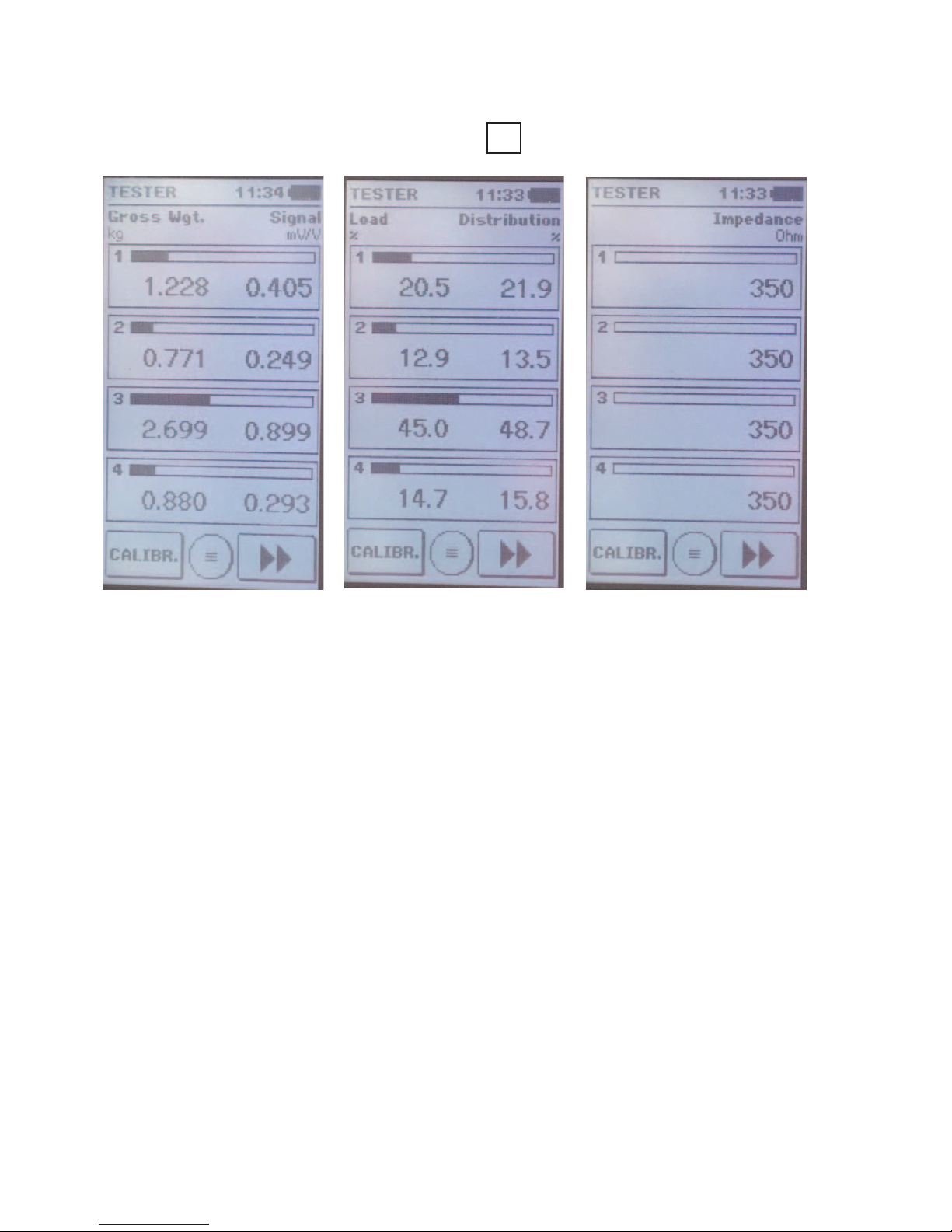
TESTER FUNCTIONS
The following displays can be selected with the key: >>
Display of “Kg” load values and
“mV / V” signal values.
The displayed values are the
weight in Kg applied to each
load cell and its “mV / V” signal.
Pressing around “Gross Weight”
it activates the autotare function
and the display shows “Net
Weight”, resetting the weight
values, the load percentage and
the distribution percentage.
Pressing again it restores the
gross weight function.
Display of load percentage and
weight distribution percentage
The displayed values are the
load percentage applied to
each load cell their distribution
percentage.
Display of the load cells input
resistance.
The impedance of each load cell
is expressed in Ohm.
It is possible to manually change
each impedance value by cli-
cking directly on the value itself
and setting the new value. When
rebooting, the values calculated
by the LC Tester 1008 tester are
restored.

Page 9
TESTER FUNCTIONS
In order to enable peak and hold functions, press impulsively on the squared box of the “Gross Weight
and Signal (mV / V)” display.
Note: Peak function only activates from the “Gross Weight and Signal” display.
The value on the left correspon-
ds to the actual weight of the
detected peak.The value on the
right corresponds to the signal
in mV / V of the load cell corre-
sponding to the weight value of
the detected peak.To delete the
detected peak values, press one
of the squared box for about 2
seconds.
The pressure, for about 2 secon-
ds, of one of the four squared
box allows storing individual
values.
The display shows the Hold di-
splay automatically.
To delete stored values, press
one of the squared box for about
2 seconds to return to the main
display.

Page 10
TESTER FUNCTIONS: AUTOTARE
The Autotare function activates by pressing the display in the highlighted area
By pressing the highlighted area
again the gross weight function
is restored and the autotare per-
formed is cancelled.

Page 11
TESTER: CALIBRATOR FUNCTIONS
Suitable for weighing instruments with load cells excitation from +/-3V to +/-15V
Reading and Display of Indicator power supply.
The display allows a complete and clear visualization the signals and their simulated gross or net weight.
CALIBRATOR Function active Clock and Batteries
Status
mV/V Signal Increment Signal Key
(+0.1 mV/V)
mV Signal End of increment Signal
Key (+0.001 mV/V)
Instrument Power supply Bar graph of the Signal and
Percentage
Weight related to the signal
Note: Set the parameters in
“Weighing Data Menu”
SLOW decreasing Signal Key
(0.001 mV/V)
Zero Key for the di-
splayed weight
FAST decreasing Signal Key
(0.1 mV/V)
Change Function Key: TESTER
/ CALIBRATOR
Average Sensitivity Signal
Simulation (3 mV/V)
Zero Signal Simulation
(0 mV/V )
Access Menu Key
ADJUSTING OUTPUT SIGNAL
The signal adjustment is managed with the cursor keys next to the Bar graph.
By holding the end adjustment keys there is a continuous signal adjustment.
The signal can be reduced to negative values up to -2.8 mV and reach the maximum value of +20.3 mV.
It is possible to manually set a value in the Signal squared box.
The Key generates the 0 mV/V Signal.
The Key generates the average Sensitivity Signal of the load cells.
In case this value is not set the default value is 2 mV/V.
Page 12
By clicking on the area “Signal” it is possible to set the desired value of
the mV/V signal to be generated.
The key performs the Autotare of the Gross weight.
In the box “weight” the heading becomes “Net weight” and the Zero Key changes and becomes:
.
By holding the Key the performed Autotare is cancelled and in the box “weight” it is
displayed “Gross Weight”.
The LC Tester 1008 simulates signals espressed in mV/V and generates the weight.
Note: The correct display of the weight generated, assumes that the parameters WEIGHING DATA:
“Load Cell Number”, “Load Cell Sensitivity”, and “Single Load Cell Capacity” are set correctly.
Example:
If the instrument to be checked is normally connected to 4 load cells of 250 kg, 2 mV / V, the LC Tester
1008 must have been programmed as follows:
Number of load cells = 4
Unit of measurement = Kg
Division value = 1
Single load cell capacity = 250 Kg
Load Cell sensitivity 1 = 2.0000
Load Cell sensitivity 2 = 2.0000
Load Cell sensitivity 3 = 2.0000
Load Cell sensitivity 4 = 2.0000
Capacity = 1000 Kg.

Page 13
MAIN MENU
This =key s it allows to access the main menu .
The main menu is made as follows:
WEIGHNG DATA MENU:
here the load cells parameter must be set
* Number of Load Cells: Selection of load cells connected to the
summing junction boxes CGS4C – CEM4C – CGS8C.
* Measurement Unit: Selection of the weight measurement unit.
* Division Value: Selection of the min. increment value of the
weight.
* Single load cell capacity: Capacity value of one of the load cells
connceted to the j box.
* Load cells Sensitivity: Sensitivity value of one of the load cells
connected to the j box.
* MAX CAPACITY OF THE SYSTEM: capacity of the weighing
system.
Note: The correct configuration of the main menu parameters
allows the correct visualization of the weights generated from the
LC Tester 1008.
SET UP MENU:
here the LC Tester 1008 operation parameters must be set.
* LCD CONTRAST and LCD BRIGHTNESS: Manual adjustment of
the LCD contrast and LCD brightness (to reduce the batteries
consumption).

Page 14
* AUTO – SWITCH OFF: Selection of the auto-switch off after a non-operative while (OFF, 3 MIN, 5
MIN, 10 MIN)
* DATE/TIME ADJUSTMENT: Manual adjustment of the clock and calendar.
By selection of and is possible to set
date and time.
* BAUD RATE RS232: Selection of the default values from 1200
to 115200 bit/sec.
* FRAME FORMAT: Selection of the data format of the RS232 serial
port (N-8-1, N-8-2, E-7-2, E-8-1, O-7-2, O-8-1).
* LANGUAGE: Selection of the language for the display: (EN-
GLISH/ITALIAN).
* MEMORY RESET: Memory reset of the System File and creation
of a File Directory.

Page 15
INSTRUMENT FILES MENU
INSTRUMENT FILES:
Management and transfer of the instrument’s Configuration Files.
These Files are stored in the directory (:\INSTR).
Here below are listed the selection menu:
* INTERFACE COMMUNICATION PORT: Selection of the interface
communication port (RS232 – NFC).
Note: NFC interface is available ONLY for Communication with
DAT1400 indicator.
* Receipt File: Selection of the configuration file stored in the
memory or creation of a new one.
Search File: It is possible to select an already existing configu-
ration. The receipt of a new file will overwrite the previous one.
New File: Creation of a new configuration with its name.
* RECEIVE FILE: In the menu, it can be selected the weight indica-
tor from which to receive the configuration (DAT400, MC302,
DAT1400 and MCT1302).
Activate the download / upload function of the connected
indicator.
The confirmation key starts the receiving phase from the LC
Tester 1008.
The message “File Received “ confirms the correct execution
of the transfer.
The “Error” message is displayed if there are errors in the
transfer.
* Transmission File: Selection of an already existing file.
Search File: It is possible to select an already existing configu-
ration which will be sent to the weight indicator connected.
* SEND FILE: The function activates the transfer of the selected
configuration in the “File” menu to the weight indicator.
The message “TRANSFER FILE” confirms the correct execution
of the transfer.
The “Error” message is displayed if there are any errors in the
transfer.

Page 16
CONFIGURATION FILES MENU
CONFIGURATION FILES:
Management of the transmission and storage of the configuration files set into the LC Tester 1008.
The files are stored in the folder (: \ CONFIG). The file extension is .csv.
Stored parameters are: Number of the Load Cells, Measurement Unit, Division Value, Load Cell Capa-
city, Load Cell Sensitivity, Capacity of the System, Zero Signals, FS Signals, Sample Weight.
• SAVE FILE: Configuration File Saving (Only possible after selecting a file in the Selected File menu).
• OPEN FILE: Upload of an existing configuration file (only possible after selecting the file). The
related data can be displayed in the Saved Signals menu.
• FILE SELECTION: You can select SEARCH FILE or NEW FILE.
Search File: Allows the automatic search of the file in the memory.
New File: Creation of a new file that will be saved in the memory.
Note: La selezione di un file già esistente non carica automaticamente la configurazione in
automatico in quanto successivamente è necessario selezionare la voce APRI FILE.
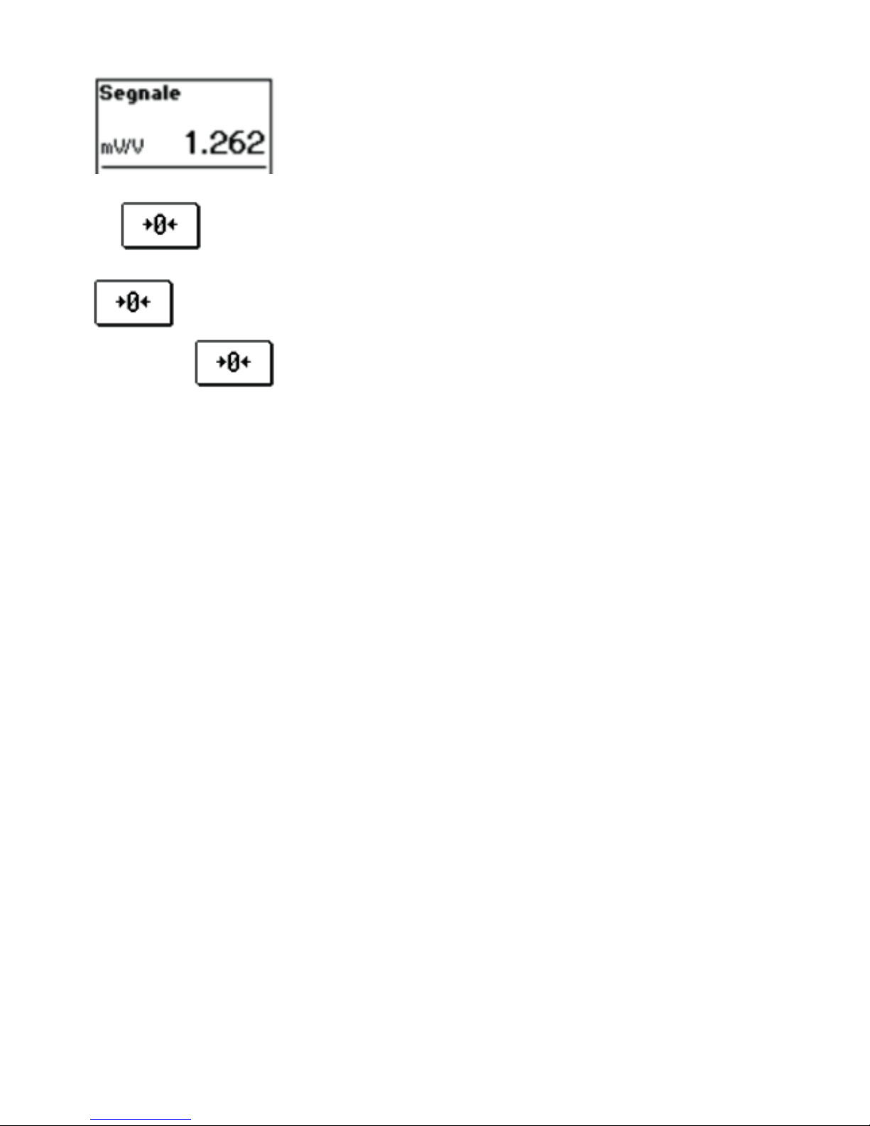
SAVE SIGNALS
This function allows to store the mV / V values coming from each load cell, both at Zero and at a
known weight. Note: These data will be associated to the current configuration file only by performing
the operation: SAVE FILE
Select to store the mV/V valuesof the weighing system
Select after the load on the system of a sample weight
and write the weight value loaded.
* STORED SIGNALS: Visualization of the Zero and F/S values
store in the menu “Load Cells Signals”

Page 17
NFC COMMUNICATION
Data exchange mode with DAT1400 with NFC option.
NFC
When receiving or transferring the file using NFC, place the LC
Tester 1008 aerial, located in the back of the container above the
batteries compartment, close to that of the instrument. When the LC
Tester 1008 has established the communication with the instrument,
the word “Reading in progress” (or “Writing in progress”) will ap-
pear. After about one second, if the data exchange is successful,
the word “Reading completed” or “Writing completed” will appear.
Note: Function only possible with the DAT1400.
Position of the NFC Aerial

Page 18
FILE MANAGEMENT FROM PC
File management functions (erasing, renaming, etc.) can only be performed from a PC via USB con-
nection (ABC cable). The PC will recognize the LC Tester 1008 as a USB remote disk.
There are two folders inside of it:
“CONFIG” containing the indicators set up files.
“INSTR” containing the system parameter saved files and the LC Tester 1008 signal files (.CSV format).
EXAMPLES: CONFIGURATION FILES
The configuration files are in .csv: format
N. LOADS: ;2;
MEASURAMENT UNIT: ;kg ;0
DIVISION VALUE: ;0.5 01 ;11
CAPACITY: ; 4000.0;
SENS1: ;2.0000;
SENS2: ;2.0000;
SENS3: ;2.0000;
SENS4: ;2.0000;
SYSTEM CAPACITY: ; 8000.0;
ZERO1: ;-0.0823;
ZERO2: ;-0.0823;
ZERO3: ;-0.0823;
ZERO4: ; 0.0714;
FS1: ; 1.9174;
FS2: ; 1.9173;
FS3: ; 1.9175;
FS4: ; 2.0819;
WEIGHT: ; 3000.0;
Table of contents
Popular Test Equipment manuals by other brands


ETH-messtechnik
ETH-messtechnik VS-PH10-10000 manual

Tektronix
Tektronix TDS1001B Security instructions

DeFelsko
DeFelsko PosiTector 6000 FNDS Addendum to instruction manual

Associated Research
Associated Research HYAMP III quick start guide

Klein Tools
Klein Tools ET510 instruction manual

Gerus
Gerus GERUTEST NTB5 Operation manual


