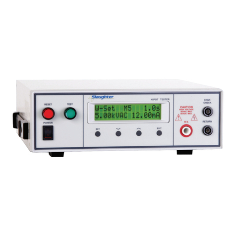
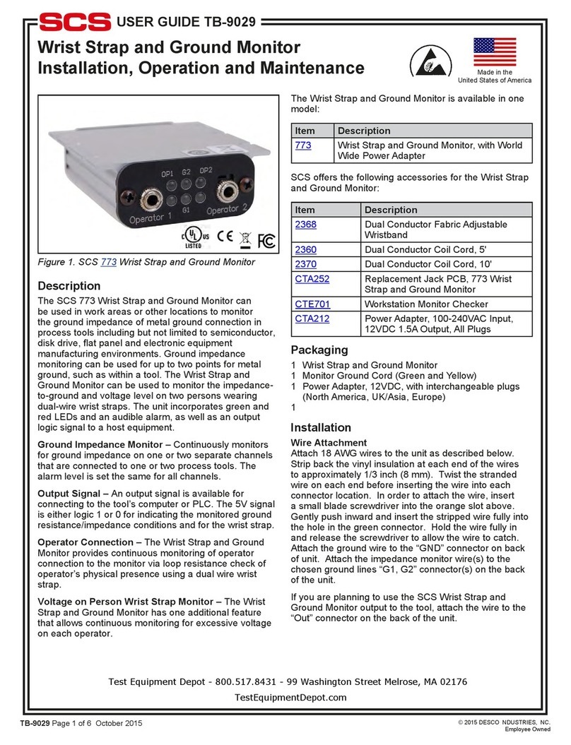
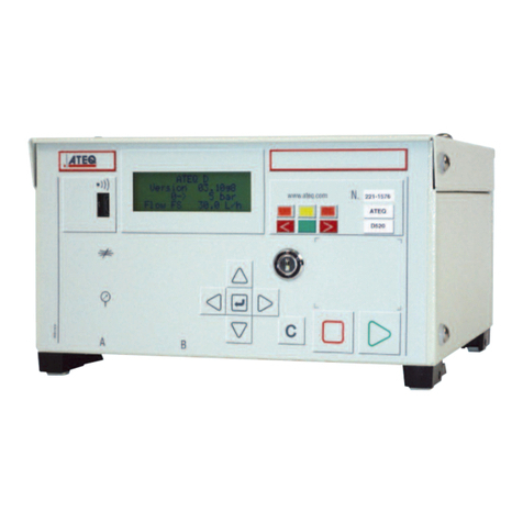
Slaughter 2925 Operation manual

OPERATION AND SERVICE MANUAL
Model 2925, 2935, 2945
MODEL 2925 (ENHANCED AC ONLY HIPOT WITH GROUND CONTINUITY CHECK)
MODEL 2935 (ENHANCED AC/DC HIPOT WITH GROUND CONTINUITY CHECK)
MODEL 2945 (ENHANCED AC/DC HIPOT WITH IR AND GROUND CONTINUITY)
SERIAL NUMBER
Models
2925,2935,2945
©Slaughter Company, Inc., 2004
28105 N. Keith Drive
Lake Forest, Illinois, 60045-4546
U.S.A.
Item 99-10090-01
Ver 1.05
Printed November 11, 2004


Warranty Policy
Slaughter Company, certifies that the instrument listed in this manual meets or exceeds
published manufacturing specifications. This instrument was calibrated using standards
that are traceable to the National Institute of Standards and Technology (NIST).
Your new instrument is warranted to be free from defects in workmanship and material
for a period of (1) year from date of shipment. You must return the “Owners Registration
Card” provided within (15) days from receipt of your instrument.
Slaughter Company recommends that your instrument be calibrated on a twelve-month
cycle. A return material authorization (RMA) must be obtained from Slaughter
Company. Please contact our Customer Support Center at 1-800-504-0055 to obtain an
RMA number. It is important that the instrument is packed in its original container for
safe transport. If the original container in not available please contact our customer
support center for proper instructions on packaging. Damages sustained as a result of
improper packaging will not be honored. Transportation costs for the return of the
instrument for warranty service must be prepaid by the customer. Slaughter Company
will assume the return freight costs when returning the instrument to the customer. The
return method will be at the discretion of Slaughter Company.
Except as provided herein, Slaughter Company makes no warranties to the purchaser of
this instrument and all other warranties, express or implied (including, without limitation,
merchantability or fitness for a particular purpose) are hereby excluded, disclaimed and
waived.
Any non-authorized modifications, tampering or physical damage will void your
warranty. Elimination of any connections in the earth grounding system or bypassing any
safety systems will void this warranty. This warranty does not cover batteries or
accessories not of Slaughter Company manufacture. Parts used must be parts that are
recommended by Slaughter Company as an acceptable specified part. Use of non-
authorized parts in the repair of this instrument will void the warranty.


i
TABLE OF CONTENTS
SECTION I OPERATORS MANUAL............................................................................1
SAFETY...........................................................................................................................2
INTRODUCTION............................................................................................................6
SPECIFICATIONS.........................................................................................................12
CONTROLS...................................................................................................................18
INSTALLATION ...........................................................................................................22
QUICK START..............................................................................................................25
OPERATION..................................................................................................................28
OPTIONS .......................................................................................................................44
SECTION II SERVICE MANUAL................................................................................47
CALIBRATION .............................................................................................................48
PARTS LIST...................................................................................................................51
SCHEMATICS...............................................................................................................52


SECTION 1
OPERATORS MANUAL

SAFETY
2
SAFETY PRECAUTIONS REQUIRED FOR HIGH
VOLTAGE TESTING!
GENERAL:
This product and its related documentation must be reviewed for familiarization with
safety markings and instructions before operation.
This product is a Safety Class I instrument (provided with a protective earth terminal).
Before applying power verify that the instrument is set to the correct line voltage (115 or
230) and the correct fuse is installed.
INSTRUCTION MANUAL SYMBOL. PLEASE REFER TO THE
INSTRUCTION MANUAL FOR SPECIFIC WARNING OR
CAUTION INFORMATION TO AVOID PERSONAL INJURY
OR DAMAGE TO THE PRODUCT.
INDICATES HAZARDOUS VOLTAGES MAY BE PRESENT.
CHASSIS GROUND SYMBOL.
CALLS ATTENTION TO A PROCEDURE, PRACTICE, OR
CONDITION, THAT COULD POSSIBLY CAUSE BODILY
INJURY OR DEATH.
CALLS ATTENTION TO A PROCEDURE, PRACTICE, OR
CONDITION, THAT COULD POSSIBLY CAUSE DAMAGE TO
EQUIPMENT OR PERMANENT LOSS OF DATA.
WARNING
CAUTION

SAFETY
3
A Hipot produces voltages and currents which can cause harmful or fatal electric
shock. To prevent accidental injury or death, these safety procedures must be strictly
observed when handling and using the test instrument.
SERVICE AND MAINTENANCE
User Service
To prevent electric shock do not remove the instrument cover. There are no user
serviceable parts inside. Routine maintenance or cleaning of internal parts is not
necessary. Any external cleaning should be done with a clean dry or slightly damp cloth.
Avoid the use of cleaning agents or chemicals to prevent any foreign liquid from entering
the cabinet through ventilation holes or damaging controls and switches, also some
chemicals may damage plastic parts or lettering. Schematics, when provided, are for
reference only. Any replacement cables and high voltage components should be acquired
directly from Slaughter Company, Inc. Refer servicing to a Slaughter Company, Inc.
authorized service center.
SLAUGHTER COMPANY, INC.
28105 N. KEITH DRIVE
LAKE FOREST, IL 60045-4546 U.S.A.
PHONE: 1 (847) 932-3662
1 (800) 504-0055
FAX: 1 (847) 932-3665
www.hipot.com
Service Interval
The instrument and its power cord, test leads, and accessories must be returned at least
once a year to a Slaughter Company authorized service center for calibration and
inspection of safety related components. Slaughter Company will not be held liable for
injuries suffered if the instrument is not returned for its annual safety check and
maintained properly.
User Modifications
Unauthorized user modifications will void your warranty. Slaughter Company will not be
responsible for any injuries sustained due to unauthorized equipment modifications or use
of parts not specified by Slaughter Company. Instruments returned to Slaughter
Company with unsafe modifications will be returned to their original operating condition
at your expense.
TEST STATION
Location
Select an area away from the main stream of activity which employees do not walk
through in performing their normal duties. If this is not practical because of production
line flow, then the area should be roped off and marked for HIGH VOLTAGE
TESTING. No employees other than the test operators should be allowed inside.

SAFETY
4
If benches are placed back-to-back, be especially careful about the use of the bench
opposite the test station. Signs should be posted: "DANGER - HIGH VOLTAGE
TEST IN PROGRESS - UNAUTHORIZED PERSONNEL KEEP AWAY."
Power
Dielectric Voltage-Withstand Test Equipment must be connected to a good ground. Be
certain that the power wiring to the test bench is properly polarized and that the proper
low resistance bonding to ground is in place.
Power to the test station should be arranged so that it can be shut off by one prominently
marked switch located at the entrance to the test area. In the event of an emergency,
anyone can cut off the power before entering the test area to offer assistance.
Work Area
Perform the tests on a nonconducting table or workbench, if possible.
There should not be any metal in the work area between the operator and the location
where products being tested will be positioned.
Position the tester so the operator does not have to reach over the product under test to
activate or adjust the tester. If the product or component being tested is small, it may be
possible to construct guards or an enclosure, made of a non-conducting material such as
clear acrylic, such that the item being tested is within the guards or enclosure during the
test, and fit them with switches so that the tester will not operate unless the guards are in
place or the enclosure closed.
Keep the area clean and uncluttered. All test equipment and test leads not absolutely
necessary for the test should be removed from the test bench and put away. It should be
clear to both the operator and to any observers which product is being tested, and which
ones are waiting to be tested or have already been tested.
Do not perform Hipot tests in a combustible atmosphere or in any area where combustible
materials are present.
TEST OPERATOR
Qualifications
This instrument generates voltages and currents which can cause harmful or fatal
electric shock and must only be operated by a skilled worker trained in its use.
The operator should understand the electrical fundamentals of voltage, current, and
resistance.
Safety Procedures
Operators should be thoroughly trained to follow these and all other applicable safety
rules and procedures before they begin a test. Defeating any safety system should be
treated as a serious offense and should result in severe penalties, such as removal from
the Hipot testing job. Allowing unauthorized personnel in the area during a test should
also be dealt with as a serious offense.

SAFETY
5
Dress
Operators should not wear jewelry which could accidentally complete a circuit.
Medical Restrictions
This instrument should not be operated by personnel with heart ailments or devices such
as pacemakers.
TEST PROCEDURES
!NEVER PERFORM A HIPOT TEST ON ENERGIZED CIRCUITRY OR EQUIPMENT!
If the instrument has an external safety-ground connection be sure that this is connected.
Then connect the return lead first for any test regardless of whether the item under test is
a sample of insulating material tested with electrodes, a component tested with the high
voltage test lead, or a cord-connected device with a two or three-prong plug.
Plug in the high voltage test lead only when it is being used. Handle its clip only by the
insulator---never touch the clip directly. Be certain that the operator has control over
any remote test switches connected to the Hipot. Double-check the return and high
voltage connections to be certain that they are proper and secure.
NEVER TOUCH THE ITEM UNDER TEST OR ANYTHING CONNECTED TO IT WHILE HIGH
VOLTAGE IS PRESENT DURING THE HIPOT TEST.
When testing with DC, always discharge the capacitance of the item
under test and anything the high voltage may have contacted--such as test
fixtures--before handling it or disconnecting the test leads.
HOT STICK probes can be used to discharge any capacitance in the item under test as a
further safety precaution. A hot stick is a nonconducting rod about two feet long with a
metal probe at the end which is connected to a wire. To discharge the device under test,
two hot sticks are required. First connect both probe wires to a good earth ground. Then
touch one probe tip to the same place the return lead was connected. While holding the
first probe in place, touch the second probe tip to the same place where the high voltage
lead was connected.
KEY SAFETY POINTS TO REMEMBER:
Keep unqualified and unauthorized personnel away from the test area.
Arrange the test station in a safe and orderly manner.
Never touch the product or connections during a test.
In case of any problem, turn off the high voltage first.
Properly discharge any item tested with DC before touching connections.
WARNING

INTRODUCTION
6
GLOSSARY OF TERMS
(as used in this manual)
Alternating Current, AC: Current which reverses direction on a regular basis, commonly in the
U.S.A. 60 times per second, in other countries 50 times per second.
Breakdown: The failure of insulation to effectively prevent the flow of current, sometimes evident by
arcing. If voltage is gradually raised, breakdown will begin suddenly at a certain voltage level. Current
flow is not directly proportional to voltage. Once breakdown current has flown, especially for a period of
time, a repeated application of voltage will often show breakdown beginning at a lower voltage than
initially.
Conductive: Having a volume resistivity of no more than 103 ohm-cm or a surface resistivity of no
more than 105 ohms per square.
Conductor: A solid or liquid material which has the ability to let current pass through it, and which has
a volume resistivity of no more than 103 ohm-cm.
Current: The movement of electrons through a conductor. Current is measured in amperes,
milliamperes, microamperes, nanoamperes, or picoamperes. Symbol = I
Dielectric: An insulating material which is positioned between two conductive materials in such a way
that a charge or voltage may appear across the two conductive materials.
Direct Current, DC: Current which flows in one direction only. The source of direct current is said
to be polarized and has one terminal which is always at a higher potential than the other.
Hipot Tester: Common term for dielectric-withstand test equipment.
Insulation: Gas, liquid or solid material which has a volume resistivity of at least 1012 ohm-cm and is
used for the purpose of resisting current flow between conductors.
Insulation Resistance Tester: An instrument or a function of an instrument capable of measuring
resistance's in excess of 200 megohms. Usually employs a higher voltage power supply than used in
ohmmeters measuring up to 200 megohms.
Leakage: AC or DC current flow through insulation and over its surfaces, and AC current flow through a
capacitance. Current flow is directly proportional to voltage. The insulation and/or capacitance is thought
of as a constant impedance, unless breakdown occurs.
Resistance: That property of a substance which impedes current and results in the dissipation of power
in the form of heat. The practical unit of resistance is the ohm. Symbol = R
Trip Point: The minimum current flow required to cause an indication of unacceptable performance
during a dielectric voltage-withstand test.
Voltage: Electrical pressure, the force which causes current through an electrical conductor.
Symbol = V

INTRODUCTION
7
INTRODUCTION
The importance of testing... User safety
In an era of soaring liability costs, original manufacturers of electrical and electronic
products must make sure every item is as safe as possible. All products must be designed
and built to prevent electric shock, even when users abuse the equipment or bypass built
in safety features.
To meet recognized safety standards, one common test is the "dielectric voltage-
withstand test". Safety agencies which require compliance safety testing at both the
initial product design stage and for routine production line testing include: Underwriters
Laboratories, Inc. (UL), the Canadian Standards Association (CSA), the International
Electrotechnical Commission (IEC), the British Standards Institution (BSI), the
Association of German Electrical Engineers (VDE), the Japanese Standards Association
(JSI). These same agencies may also require that an insulation resistance test and high
current ground bond test be performed.
The Dielectric Withstand (Hipot) Test....
The principle behind a dielectric voltage - withstand test is simple. If a product will
function when exposed to extremely adverse conditions, it can be assumed that the
product will function in normal operating circumstances.
The most common applications of the dielectric-withstand test are:
Design (performance) Testing.... determining design adequacy to meet service
conditions.
Production Line Testing.... detecting defects in material or workmanship during
processing.
Acceptance Testing.... proving minimum insulation requirements of purchased parts.
Repair Service Testing.... determine reliability and safety of equipment repairs.
The specific technique varies with each product, but basically, during a dielectric voltage
- withstand test, an electrical devise is exposed to a voltage significantly higher than it
normally encounters. The high voltage is continued for a given period.
If, during the time the component is tested, stray current flow remains within specified
limits, the device is assumed safe under normal conditions. The basic product design and
use of the insulating material will protect the user against electrical shock.
The equipment used for this test, a dielectric-withstand tester, is often called a "hipot"
(for high potential tester). The "rule of thumb" for testing is to subject the product to
twice its normal operating voltage, plus 1,000 volts.

INTRODUCTION
8
However, specific products may be tested at much higher voltages than 2X operating
voltages + 1,000 volts. For example, a product designed to operate in the range between
100 to 240 volts, can be tested between 1,000 to 4,000 volts or higher. Most "double
insulated" products are tested at voltages much higher than the "rule of thumb".
Testing during development and prototype stages is more stringent than production run
tests because the basic design of the product is being evaluated. Design tests usually are
performed on only a few samples of the product. Production tests are performed on each
and every item as it comes off the production line.
The hipot tester must also maintain an output voltage between 100% and 120% of
specification. The output voltage of the hipot must have a sinusoidal waveform with a
frequency between 40 to 70 Hz and has a peak waveform value that is not less than 1.3
and not more than 1.5 times the root-mean-square value.
Advantages and Disadvantages of AC Testing and DC Testing....
Please check with the Compliance Agency you are working with to see which of the two
types of voltages you are authorized to use. In some cases, a Compliance Agency will
allow either AC or DC testing to be done. However, in other cases the Compliance
Agency only allows for an AC test. If you are unsure which specification you must
comply with please contact our CUSTOMER SUPPORT GROUP at 1-800-504-0055.
Many safety agency specifications allow either AC or DC voltages to be used during the
hipot test. When this is the case, the manufacturer must make the decision on which type
of voltage to utilize. In order to do this it is important to understand the advantages and
the disadvantages of both AC and DC testing.
AC testing characteristics
Most items that are hipot tested have some amount of distributed capacitance. An AC
voltage cannot charge this capacitance so it continually reads the reactive current that
flows when AC is applied to a capacitive load.
AC testing advantages
1. AC testing is generally much more accepted by safety agencies than DC testing.
The main reason for this is that most items being hipot tested will operate at AC
voltages and AC hipot testing offers the advantage of stressing the insulation
alternately in both polarities which more closely simulates stresses the product will
see in real use.
2. Since AC testing cannot charge a capacitive load the current reading remains
consistent from initial application of the voltage to the end of the test. Therefore,
there is no need to gradually bring up the voltage since there is no stabilization
required to monitor the current reading. This means that unless the product is

INTRODUCTION
9
sensitive to a sudden application of voltage the operator can immediately apply full
voltage and read current without any wait time.
3. Another advantage of AC testing is that since AC voltage cannot charge a load there
is no need to discharge the item under test after the test.
AC testing disadvantages
1. A key disadvantage of AC testing surfaces when testing capacitive products. Again,
since AC cannot charge the item under test, reactive current is constantly flowing.
In many cases, the reactive component of the current can be much greater than the
real component due to actual leakage. This can make it very difficult to detect
products that have excessively high leakage current.
2. Another disadvantage of AC testing is that the hipot has to have the capability of
supplying reactive and leakage current continuously. This may require a current
output that is actually much higher than is really required to monitor leakage current
and in most cases is usually much higher than would be needed with DC testing.
This can present increased safety risks as operators are exposed to higher currents.
DC testing characteristics
During DC hipot testing the item under test is charged. The same test item capacitance
that causes reactive current in AC testing results in initial charging current which
exponentially drops to zero in DC testing.
DC testing advantages
1. Once the item under test is fully charged the only current flowing is true leakage
current. This allows a DC hipot tester to clearly display only the true leakage of the
product under test.
2. The other advantage to DC testing is that since the charging current only needs to be
applied momentarily the output power requirements of the DC hipot tester can
typically be much less than what would be required in an AC tester to test the same
product.
DC testing disadvantages
1. Unless the item being tested has virtually no capacitance it is necessary to raise the
voltage gradually from zero to the full test voltage. The more capacitive the item the
more slowly the voltage must be raised. This is important since most DC hipots
have failure shut off circuitry which will indicate failure almost immediately if the
total current reaches the leakage threshold during the initial charging of the product
under test.

INTRODUCTION
10
2. Since a DC hipot does charge the item under test it becomes necessary to discharge
the item after the test.
3. DC testing unlike AC testing only charges the insulation in one polarity. This
becomes a concern when testing products that will actually be used at AC voltages.
This is a key reason that some safety agencies do not accept DC testing as an
alternative to AC.
4. When performing AC hipot tests the product under test is actually tested with peak
voltages that the hipot meter does not display. This is not the case with DC testing
since a sinewave is not generated when testing with direct current. In order to
compensate for this most safety agencies require that the equivalent DC test be
performed at higher voltages than the AC test. The multiplying factor is somewhat
inconsistent between agencies which can cause confusion concerning exactly what
equivalent DC test voltage is appropriate.
The Ground Continuity Test
The Ground Continuity test is checking to verify that there is low impedance path
between the chassis and the safety ground wire of the line cord. A low impedance ground
system is critical in ensuring that in the event of a product failure a circuit breaker on the
input line will act quickly to protect the user from any serious electrical shock.
International compliance agencies such as CSA, IEC, TÜV, VDE, BABT, and others,
have requirements calling out this test. A low current test merely indicates that there is a
safety ground connection, it does not completely test the integrity of that connection that
would be accomplished when using much higher currents in the range from 10 to 30amps.
The high current test is known as a Ground Bond test.
The Ground Continuity test verifies that the ground circuit between the Continuity and
Return panel jacks on the Hipot is below 1ohm while test at a current of 100mA. This
function can be enabled or disabled through software, when a ground circuit is not
provided on the device under test or test requirement are not needed.
The Insulation Resistance Test....
Some "dielectric analyzers today come with a built in insulation resistance tester.
Typically, the IR function provides test voltages from 500 to 1,000 volts DC and
resistance ranges from kilohms to gigaohms. This function allows manufacturers to
comply with special compliance regulations. BABT, TÜV, and VDE are agencies that
may under certain conditions require an IR test on the product before a Hipot test is
performed. This typically is not a production line test but a performance design test.
The insulation resistance test is very similar to the hipot test. Instead of the go/no go
indication that you get with a hipot test the IR test gives you an insulation value usually in
Megohms. Typically the higher the insulation resistance value the better the condition of
the insulation. The connections to perform the IR test are the same as the hipot test. The

INTRODUCTION
11
measured value represents the equivalent resistance of all the insulation which exists
between the two points and any component resistance which might also be connected
between the two points.
Although the IR test can be a predictor of insulation condition, it does not replace the
need to perform a Dielectric Withstand test.
TYPES OF FAILURES DETECTABLE ONLY WITH A HIPOT TEST
Weak Insulating Materials
Pinholes in Insulation
Inadequate Spacing of Components
Pinched Insulation
IF YOU SHOULD HAVE ANY QUESTIONS RELATING TO THE OPERATION
OF YOUR INSTRUMENT CALL 1 (800) 504-0055 IN THE U.S.A.

SPECIFICATIONS
12
Model 2925, 2935, and 2945
Functional Specifications
Unless otherwise stated, accuracy's are relative to a laboratory standard measurement.
DIELECTRIC WITHSTAND TEST MODE
Descriptions
Specifications
INPUT VOLTAGE
115 / 230V selectable, 10 variation
FREQUENCY
50 / 60 Hz 5%
FUSE
115 VAC, 230VAC -- 3.15A fast acting 250VAC
OUTPUT
Rating AC 0 - 5000V, 2V / step, 12mA
DC 0 - 6000V, 2V / step, 5mA
(DC mode on 2935 and 2945)
Regulation : (1 of output 5V)
VOLTAGE SETTING
0V - Max output rating, 10 volts/step
Accuracy : (2 of Setting 5V) (relative to displayed
output)
Can be adjusted during operation via UP and DOWN arrow
keys.
OUTPUT
FREQUENCY
2925 : 50 / 60 Hz selectable
2935 and 2945 : DC and 50 / 60 Hz selectable
WAVE FORM
Sinewave, Distortion : 2 THD
RIPPLE
5 at 6KVDC / 5mA (2935 and 2945)
DWELL TIME
SETTING
0 and 0.2 - 999.9 seconds, 0.1 second / step
“0” for continuous running
RAMP TIME
SETTING
Model 2925, 2935, and 2945
0 and 0.2 - 999.9 seconds, 0.1 second / step
0 ramp setting = 0.1 seconds fixed ramp
Model 2925
Ramp = 0.1 seconds fixed
FAILURE SETTINGS
AC mode
High limit : 0.10 - 12.00 mA, 0.01 mA / step
Low limit : 0.00, 0.10 - 12.00 mA, 0.01 mA / step (0= OFF)
(2925, 2935, and 2945)
Accuracy: (2 of setting 0.02 mA)
DC mode
High limit : 0.02 - 5.00 mA, 0.01 mA / step
Low limit : 0.00, 0.02 - 5.00 mA, 0.01 mA / step (0= OFF)
(2925, 2935, and 2945)
Accuracy : (2 of setting 0.02 mA)

SPECIFICATIONS
13
Descriptions
Specifications
METERING
Voltmeter (4 digits)
Range : AC 0.00 - 5.00 KV
: DC 0.00 - 6.00 KV
Resolution : .01 KV
Accuracy : (2 of reading 10 V)
Ammeter (4 digits)
Range : AC 0.10 - 12.00 mA
: DC 0.02 - 5.00 mA
Resolution : 0.01 mA
Accuracy : (2 of reading 0.02mA)
TIMER DISPLAY
Range : 0.0 - 999.9 seconds
Resolution : 0.1 second
Accuracy : (0.1 of reading 0.05 seconds)
DISCHARGE TIME
300 ms
The maximum capacitive load vs. output voltage :
0.20 F --- 1KV
0.10 F --- 2KV
0.06 F --- 3KV
0.050 F --- 4KV
0.040 F --- 5KV
0.015 F --- 6KV
GROUND
CONTINUITY CHECK
Current : DC 0.1 A 0.01A, fixed
Max. ground resistance : 1 0.1, fixed
INSULATION RESISTANCE TEST MODE
Output Voltage
Range:
100 - 1000 Volts DC
Resolution:
10 volt/step
Accuracy:
(2of reading 5 volts)
Voltage Display
Range:
0 - 1000 V
Resolution:
10 volt/step
Accuracy:
(2of reading 2 counts)
Resistance Display
Range:
1 - 1000 M(4 Digit, Auto Ranging)
Resolution:
500VDC
1000VDC
M
M
M
0.01
1.00 - 40.00
1.00 - 80.00
0.1
35.0 - 999.9
75.0 - 999.9
Accuracy:
(3of reading 2 counts)
at test voltage > 500V
(7of reading 2 counts)
at test voltage 500V

SPECIFICATIONS
14
Descriptions
Specifications
High Resistance Limit
Range:
0 - 1000 M(0 = Off)
Low Resistance Limit
Range:
1 - 1000 M
Delay Timer
Range:
0, 0.5 - 999.9 sec (0 = Constant)
Resolution:
0.1 sec/step
Accuracy:
(0.1% + 0.05 sec)
GENERAL
REMOTE CONTROL
AND SIGNAL
OUTPUT
The following input and output signals are provided through
the 9 pin D type connector;
1. Remote control : test and reset
2. Outputs : pass, fail and test in process
PROGRAM MEMORY
5 Sets (2925, 2935, and 2945)
SECURITY
Key Lock capability to avoid unauthorized access to all test
parameters. Memory Lock capability to avoid unauthorized
access to memory locations.
LINE CORD
Detachable 7 ft. (2.13m) power cable terminated in a three-
prong grounding plug.
TERMINATIONS
5ft.(1.52m) high voltage and return leads (2) with clips. An
optional remote receptacle box may be purchased for testing
items terminated with a line cord. International receptacles are
also available.
MECHANICAL
Tilt up front feet.
Dimensions: (W x H x D) 11 x 3.5 x 14.56 in. (280 x 89 x 370 mm)
Weight: 20 lbs (9 Kgs)
ENVIRONMENTAL
Operating Temperature : 32- 113F (0- 45C)
Relative Humidity - 0 to 95%
CALIBRATION
Traceable to National Institute of Standards and Technology
(NIST). Calibration controlled by software. Adjustments are
made through front panel keypad in a restricted access
calibration mode. Calibration information stored in non-
volatile memory.
This manual suits for next models
2
Table of contents
Other Slaughter Test Equipment manuals
Popular Test Equipment manuals by other brands
Associated Research
Associated Research HypotULTRA 7800 quick start guide
GRAS
GRAS 43AG Series instruction manual

Desco
Desco 19240 Installation, operation and maintenance manual

Philips
Philips Optimus manual

GDD Instrumentation
GDD Instrumentation TDLV instruction manual

SP tools
SP tools SP61062 user manual
