Pavone Systems MC 315 Series User manual

Pavone Sistemi
pesatura elettronica industriale
Pavone Sistemi
pesatura elettronica industriale
PAVONESYSTEMS
TECHNICAL MANUAL
MC 315 Weight Indicator wit serial outputs, fiber optics, IN/OUT
Software version PATX02

Page II

Rel ID 20190201 SW 0.5
Page 1
TABLE OF CONTENTS
PRECAUTIONS.............................................................................................. P. 2
INTRODUCTION ........................................................................................... P. 3
TECHNICAL CHARACTERISTICS ..................................................................... P. 5
INSTALLATION ............................................................................................. P. 6
FRONT PANEL OF THE UNIT………. .............................................................. P. 14
USE OF THE KEYBOARD ................................................................................ P. 15
DISPLAY INFO .............................................................................................. P. 18
OPERATING FUNCTIONS ............................................................................. P. 19
CONFIGURATION......................................................................................... P. 23
SET-UP MENU DIAGRAM ............................................................................... P. 27
CONFIGURATION PARAMETERS .................................................................... P. 28
CALIBRATION ............................................................................................... P. 28
SERIAL OUTPUT PARAMETERS ........................................................................ P. 35
INPUT/OUTPUT PARAMETERS......................................................................... P. 44
WEIGHING PARAMETERS ............................................................................. P. 48
FILTER PARAMETERS ....................................................................................... P. 50
SET-UP OF FUNCTIONAL FEATURES ............................................................... P. 52
DATE AND TIME ADJUSTMENT ...................................................................... P. 55
UPLOAD/DOWNLOAD FUNCTION ................................................................ P. 56
ACCESS DISPLAY .......................................................................................... P. 57
ALIBI MEMORY CONSULTATION..................................................................... P. 58
SERIAL COMMUNICATION PROTOCOLS ........................................................ P. 59
TROUBLESHOOTING .................................................................................... P. 84

Page 2
PRECAUTIONS
READ this manual BEFORE using or maintaining the unit.
FOLLOW these instructions carefully.
STORE this manual for future reference.
WARNING
This manual uses words and explanatory images to help the operator understand the pre-
scriptions and fundamental criteria for the installation and appropriate use of the unit.
Installation, maintenance, and repairs should only be performed by specialized operators
after reading and understanding this manual. “Specialized operators” means the staff that,
having the necessary professional training and expertise, were expressly authorized by the
plant’s safety Manager to perform installation.
Power the unit within the voltage limits specified in the characteristics.
The user is responsible to ensure that installation complies with the applicable rules in force.
Any attempt to dismantle or modify the unit shall make the relevant guarantee null and void
and release Pavone Sistemi from any and all liabilities, except where expressly authorized.
The installation and maintenance of this unit should only be performed by qualified staff.
Utmost care should be taken when performing checks, tests, and adjustments with the unit
switched on.
Power connections should only be performed when the unit is switched off.
Any failure to comply with the above precautions may imply risks.
DO NOT ALLOW untrained staff to operate, clean, inspect, repair, or tamper with this unit.
The unit bears the following ATEX mark:
II2(1) G Ex ia [ia IIC Ga] IIC T4 Ga (Ta: -10°C ÷ +40°C)
II2(1) D Ex ia [ia IIC Da] IIC T135°C Db X (Ta: -10°C ÷ +40°C)
The unit was approved for specific usage locations: do not install or use the unit in locations
other than the specified ones.
The safety of the weighing system is only ensured if installed and used according to the
provisions contained herein.
Do not open the unit when switched on, do not disconnect the cables when switched on,
do not open in explosive atmospheres.
Do not cover the unit with materials subject to potential electrostatic charge.
Clean the unit with moist cloths and anti-static products.
All peripheral devices connected with the unit, if installed and operated in the same location,
should be marked at least II 1 GD.
Do not connect the unit with modules that are not provided for by the certification; this af-
fects the intrinsic safety of the unit (with subsequent loss of the Ex approval). Please refer to
Pavone Sistemi srl for additional information.

Page 3
INTRODUCTION
The MC 315 is a weighing unit designed and manufactured in accordance with directive 2014/34/
EU, fit for use in locations with potentially explosive atmospheres in compliance with norms EN 60079-
0:2018, EN 60079-11:2012, and EN 60079-26:2015.
Operation is allowed in zones 1, 21, and 2, 22 (1, 2 for gases, 21, 22 for powders) as per Directive
ATEX 2014/34/EU.
Operation in zones subject to the risk of explosion is safe because the indicator uses low energy, which
is not sufficient to trigger explosions either with power sparkles or with excess temperatures (class T4).
The weighing terminal features a centralized CPU, a LED display, a membrane keyboard, and a se-
parate power pack, which should be located in a safe zone or placed in a separately ATEX-certified
enclosure when installed in a dangerous zone; such power pack is made up of a dedicated AL-AX
power unit or an AL-BX battery pack.
The unit can be placed on a table or hung on the wall by means of an optional bracket.
The display ensures easy reading of weight, unit status, configuration parameters, and errors.
The multi-function 21-key keyboard ensures smooth performance of the following functions: ZERO,
TARE, GROSS/NET switching, weight set point set-up, configuration, and calibration, both theoretical
and actual.
The optical fiber connection allows to convey to a safe zone the information required to calculate, via
the S3xx interface, the analogue voltage or current output, IN-OUT, RS232, and RS485, without using
any Zener barriers.
Two RS485 serial ports with ASCII or MODBUS protocol allow remote connection for a maximum of
32 addressable devices, both in a safe and in a dangerous zone, using specific Zener barriers.
Two optoinsulated inputs are also available and can be connected with devices both in a dangerous and
in a safe zone, as well as 6 photorelay outputs that can be connected with devices in a dangerous zone.
Available versions:
• MC315:weightindicatorwithopticalfiberoutput,2RS485serialports.Supportsthe
ASCII and Modbus RTU continuous protocols. Two inputs and 6 outputs.
• MC315/X:versionwithXXXXX.
• MC315/XXX:XXXXXXXXXXXXX.

PAVONE SISTEMI
Page 4
NAMEPLATE OF THE UNIT
It is important to communicate this information when inquiring about the unit, alongside the number of
the software application and version stated on the cover of the manual and displayed when the unit
is switched on.
WARNING
The procedures described below should be performed by specialized staff.
All connections should be performed when the unit is switched off.

Page 5
TECHNICAL CHARACTERISTICS
Power 100 ÷ 250 VAC with AL-AX certified power unit or 6V
battery via AL-BX barrier (in safe zones)
Max absorption 2 W
Insulation Class III
Operating temperature -10°C ÷ +50°C (max. steam-free humidity 85%)
Storage temperature -20°C ÷ +60°C
Weight display Red 6-digit 7-segment LEDs (h 20 mm)
LEDs 8 LED indicators 5mm
Keyboard membrane, 20 keys + ON/OFF
Dimensions 237 mm x 169 mm x 113 mm (l x h x d)
Mounting Table-top, wall-mount, or column (with bracket)
Enclosure material Stainless steel
Connections Removable terminal pads with pitch 3.81 screws
Load cell power supply Max 4 350Ω cells in parallel, protected from short
circuits
Input sensitivity 0.02 µV min.
Linearity < 0.01% of full scale
Thermal drift < 0.002% of full scale / C°
Internal resolution 24 bits
Weight display resolution Up to 999.999 divisions of maximum capacity
Measurement field –3,9 mV/V to +3,9 mV/V
Weight acquisition frequency 50 Hz
Digital filter Can be selected on 10 level
Number of weight decimals 0 to 4 decimals
Zero point and full scale calibration Automated (theoretical) or executable from keyboard
Logical outputs 6 photorelays max 24 Vdc / 100 mA each
Logical inputs 2 optoinsulated at 12÷24 Vdc PNP (external supply)
Serial port (No. 2) RS485
Max. cable length 200m
Serial protocols ASCII, Modbus RTU
Full duplex fiber optic port Data transmission to S318 circuit board in safe zones
Max. cable length 50m
Cable type Duplex cable with 1 mm Plastic Fiber optics (e.g. COP-
1002-HD)
Microcontroller: ARM Cortex M0+ 32 bit, 256KB Flash resettable on-
board from USB.
Data storage 256 Kbytes expandable to 1024 Kbytes
Compliance with norms EN61000-6-2, EN61000-6-3, EN61010-1
EN60079-0, EN60079-11, EN60079-26

175
99
30
177
97
35
55
202
230
DIS1DIS2DIS3DIS4DIS5DIS6
LED1LED2LED3LED4L E D5LED6
ED8
SX 1 1
DX
UP 1 2
14 15
17 18
1CLR 10
3
6
9
PRG
SHF ON
ZERO
1 2
4 5
7 8
CLR 0
3
6
9
PRG
TARE
SHFFUN ON
MC 315
Page 6
INSTALLATION
OVERVIEW
The MC 315 is a multifunction unit contained in a stainless steel enclosure, fit for use in zones subject
to the risk of explosion as per Directive ATEX 2014-34-EU, in accordance with norms EN 60079-0 and
EN 60079-11 Ex-I (Intrinsic Safety).
The MC 315 should not be soaked in water, splashed with water, and cleaned or washed
with solvents.
Do not expose the unit to high temperatures or direct sun light.
Do not install the unit near power equipment (engines, inverters, contactors, etc.) or equipment that
does not comply with EC norms for electromagnetic compatibility.
Follow the guidelines in the unit safety manual and the reference ATEX norms.
DIMENSIONS
POWER INSTALLATION
Cables are fed into the enclosure through six separately “II2G Ex e”-certified cable glands
arranged across the back wall.
The eligible models are selected by Pavone Sistemi: in case of damage and decay, they should
be replaced by Pavone Sistemi.
Unused cable glands should always be closed with the appropriate supplied separable plug, which
restores protection degree IP66.
Cables used with cable glands should be selected in accordance with EN60079-14 and should be
round, compact, full extruded, and non-hygroscopic.
The internal power connection of the MC 315 indicator is performed with removable terminal pads
with pitch 3.81 screws.
L N
- +
Power Supply
AL-AX
Dangerous zone
Safe zone
Output
5Vdc 0.2A
Input
115/230 Vac
115/230 Vac
Power Supply
+5 Vdc
0 Vdc
N
L
EXC-
EXC+
SENSE+
SENSE-
SIG-
SIG+
SHIELD +
-+5 Vdc
0 Vdc
AL-AX
Power Supply
Page 7
POWER SUPPLY OF THE UNIT
The circuit board is powered via an AL-AX certified power unit
(100 ÷250 VAC / 5VDC) or a 6V battery via AL-BX barrier. Both
the power unit and the battery should be located in a safe zone
or, if located in a Dangerous Zone, should be contained within a
separately certified ATEX enclosure.
The unit is powered through terminals 1 and 2 of connector J1. The
power cable should be fed separately from other cables.
Ensure that appropriate grounding is available.
Power supply voltage: 5 VCC ±15%, max 2W
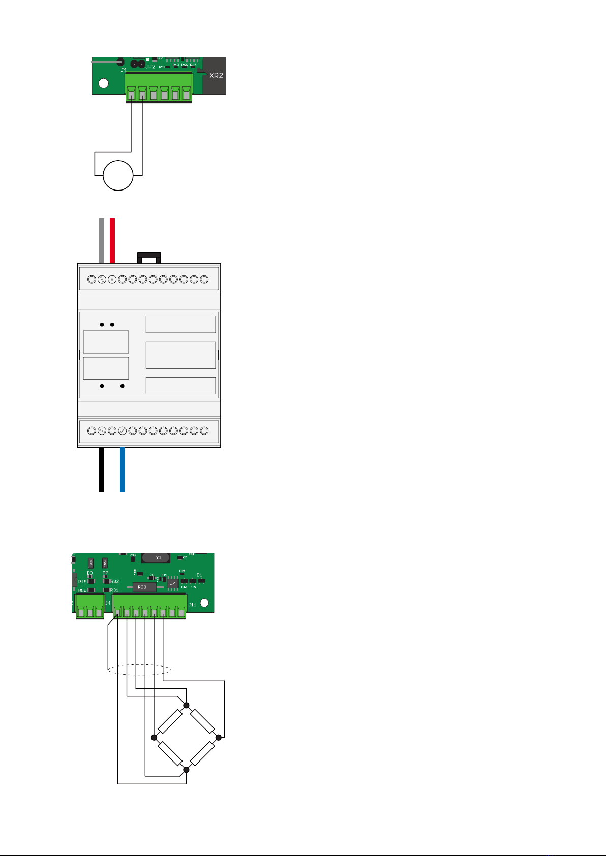
LOAD CELL CONNECTION
The cells’ cable should not be fed together with other cables, but
should follow its own separate path.
Up to 4 350-ohm cells can be connected in parallel with the unit.
The cells’ power supply voltage is 3.3 VCC, with protection from
temporary short circuits.
The measurement field of the unit provides for using load cells with
maximum 3.9 mV/V sensitivity.
The load cells’ cable should be connected with terminals 1 to 6 of
connector J11. In case of 4-conductor cell cable, bridge terminal 1
with 4 and terminal 2 with 3.
Connect the cells’ cable shield with terminal 1 of connector J11.
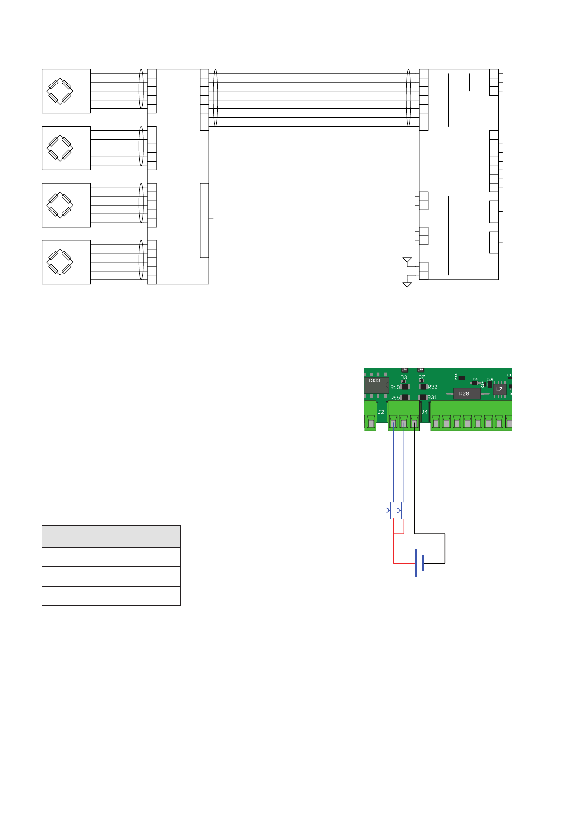
If two or more load cells are used, use specific junction boxes
(CEM4/E ATEX or CSG4/C ATEX), connected as shown below.
+EXC
-EXC
+SGN
-SGN
SHD
+EXC
-EXC
+SGN
-SGN
SHD
+EXC
-EXC
+SGN
-SGN
SHD
+EXC
-EXC
+SGN
-SGN
SHD
25 PIN CONNECTOR
+SGN
-ALM
+ALM
-SGN
+SNS
-SNS
+ALM
-ALM
+SGN
-SGN
+ALM
-ALM
+SGN
-SGN
+ALM
-ALM
+SGN
-SGN
+ALM
-ALM
+SGN
-SGN
SCH
SCH
SCH
SCH
SCH
2
3
6
1
5
4
7
1
2
3
4
5
1
2
3
4
5
1
2
3
4
5
1
2
3
4
5
J-BOX CGS4C ATEX
XR2
MC 315
TX+/RX+
TX-/RX-
-SENSE
+SENSE
SHIELD
TX+/RX+
TX-/RX-
-SIG1
+SIG1
COM OU
COM IN
OUT2
-EXC
+EXC
OUT1
OUT3
OUT4
OUT5
OUT6
IN2
IN15
6
1
4
3
2
1
2
00
7
3
4
5
6
3
4
5
6
2
1
2
+Vin
GND
1
3
+5V
XT1
J1
COM1
COM2
J11
J4J2
OPTICAL FIBER
+
-
INPUT 2
INPUT 1
24 Vdc
100 mA Max
COM. INPUT
Page 8
LOGICAL INPUT CONNECTION
Logical inputs are insulated from the unit by means of optoinsulators
with minimum inner distance of 0.5 mm. This allows to connect inputs
located both in a safe and in a dangerous zone.
• The connection cables of the logical inputs should not be fed
together with power or supply cables.
• The connection cable should be as short as possible.
Logical input enabling requires a 7 to 24 VDC voltage. The com-
mon inputs should be connected with the negative having the same
voltage.
NUM. Terminal Board J4
1 Input 1
2 Input 2
3 Common Input
OUTPUTS
30 Vdc
100 mA Max
OUTPUT 2
OUTPUT 1
COM. OUTPUT
OUTPUT 3
OUTPUT 4
OUTPUT 5
OUTPUT 6
COM1
RS485 TX-/RX-
TX+/RX+
COM2
RS485 TX-/RX-
TX+/RX+
SHIELD
Page 9
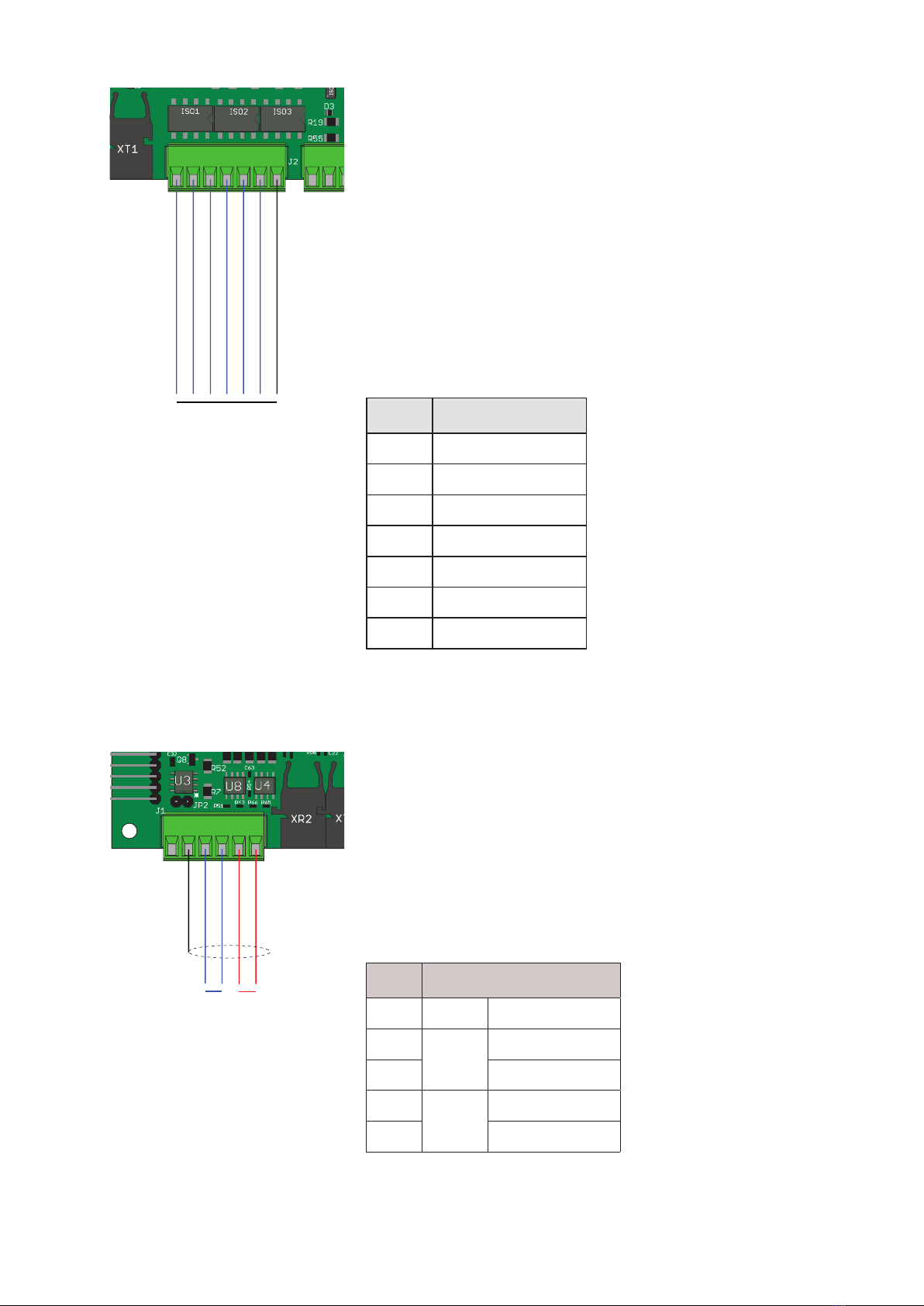
LOGICAL OUTPUT CONNECTION
The 6 logical outputs are based on a Photorelay (clean contact) with
a common. The capacity of each contact is 100 mA / 30VDC. When
the output is enabled, the contact closes (contact NA).
• The location that hosts to the unit can be normally subject to strong
magnetic fields and electrical noises caused by other appliances.
Therefore ordinary measures should be taken to prevent any
impact thereof on the typical signals of a high-precision electro-
nic device (filters on contactors, diodes on 24 Vdc relays, etc.).
The outputs are designed to drive devices through a dangerous zone.
For use with devices in a safe zone, an optical fiber connection or
a specific barrier can be used.
Output connection is shown below:
NUM. Terminal board J2
1 Output 1
2 Output 2
3 Output 3
4 Output 4
5 Output 5
6 Output 6
7 Common Output
SERIAL COMMUNICATION
RS485
Serial connections for distances up to 200m can be performed via the
RS485 serial interface. The RS485 serial connection is of the 2-thread
type and allows to connect up to 32 devices with one MASTER unit
(personal computer, PLC, etc.) via one twisted and shielded cable.
The cable shield should be connected with terminal 2 of connector J1.
The cable should not be fed together with power cables.
A RS485 barrier must be used to connect the MC 315 (in a dange-
rous zone) with a PC or other devices in a safe zone. Several models
are available on sale, including the D1061S by GM International.
NUM. Morsettiera J1
2 SHIELD
3COM1 TX+/RX+
4 TX-/RX-
5COM2 TX+/RX+
6 TX-/RX-

USB+
Fiber Optic Interface
Fiber Optic
RX TX
Options:
Fiber Optic
A Gnd
TX
RX
Out An
V Out +
I Out +
S Gnd
RxD
TxD
RS485 -
RS485 +
GND
+ Vdc
+
-
GND
7÷30 Vdc
V+ (10 kΩ min)
mA+ (300 Ω max)
RS485
TX-/RX-
TX+/RX+
ANALOG
OUTPUT RS232
RXD
TXD
SGND
A Gnd
Page 10
OPTICAL FIBER CONNECTION
The use of optical fiber communication systems in dangerous zones
offers some advantages in terms of galvanic isolation and use of
low energy.
Galvanic isolation makes it unnecessary to use a barrier, which would
be anyway required between the dangerous and the safe zone in
case of, for example, RS232 or RS485 communication or analogical
output, even if the signals come from an intrinsically safe unit.
The use of diffused-light LEDs, as for the interfaces on this unit, com-
plies with the ATEX norms and, specifically, with norm EN 60079-28.
Two-way optical fiber communication allows to send and receive
data in a safe zone to/from the S318 circuit board; such data is
then switched to Fieldbus, RS485, RS232, analogical outputs, in-out.
The requested cable is a Duplex cable with two fibres inside the
same sheath, with 1mm Plastic Optical Fiber (e.g. COP-1002-HD).
The fiber terminal should be designed according to document
“AV02-0460EN _DS_HFBR-
453xZ_2015-06-18.PDF”
by AVAGO/BROADCOM, and
using connectors of the HFBR-
453xZ series.
The use of two different colours
for the TX and RX, is recommen-
ded, e.g. HFBR-4531Z (black)
for the TX and HFBR-4533Z
(blue, see photo on the right) for
the RX.
The optical fiber could reach a
maximum length of 100m (as from the characteristics) with a very
accurate finish, as specified in the above-mentioned document.
If the finish is not ascertained, a maximum length of 50m is recom-
mended.
The fibers can also be cut with an appropriate cutter (see figure).
S318 CIRCUIT BOARD
The Optical Fiber interface board is contained in a plastic enclosure
with DIN 35mm guide. Its size is 70x90x58mm (LxHxD). While the
board should be powered at the typical voltage rate of 24 VDC,
voltage values between 7 and 30 VDC are also accepted.
The base version of the board features a RS232 serial port and a
RS485 serial port. It is also available with analogical voltage or
current output as an option.
As an alternative to the RS485 serial port, any of the following
FIELDBUS options can be used: Profibus DP, Profinet, Ethercat, or
Ethernet IP.
The configuration of the serial ports, of the analogical output and
of the Fieldbus (if any) is performed directly by the MC 315 unit.

MC 315
Kg
T
RO
1
ZE
2
4 5
7 8
CLR 0
3
6
9
PRG
ARE
SHFFUN ON
Page 11
FRONT PANEL OF THE UNIT
The MC 315 has a bright 6-digit display, 8 status LEDs, and 21 keys for easy operation. In the operating
mode, the display shows the weight, and the LEDs indicate the weight and set point status.
The set-up parameters are easy to access and adjust using the front keys to select, change, and confirm
the new values.
DISPLAY
The 6-digit display usually shows the scale weight. Based on the different set-up processes, the display
is used to set up the parameters to be saved, i.e. messages about the current operation mode, and
therefore ensure smooth user operation and set-up of the unit.
LEDS
The 6 status LEDs above the display have the following functions:
BAT Battery operation / battery low (flashing)
FUN Function key enabled
NET Net weight display (entered tare)
MIN Gross weight below the set zero band
>0< Zero point (gross weight < 0,25 e)
Stable weight
There are 2 LEDs on the left side of the display:
1 Multirange field 1
2 Multirange field 2. ( 1 + 2 ) = Multirange field 3.
Page 12
USE OF THE KEYBOARD
The unit is set up and controlled via the 21-key keyboard. Set-up menus are usually managed by pressing
the arrow keys to scroll the items and the PRG key to access the relevant sub-menu or programmable
parameter.
The ON key allows to switch the unit on and off.
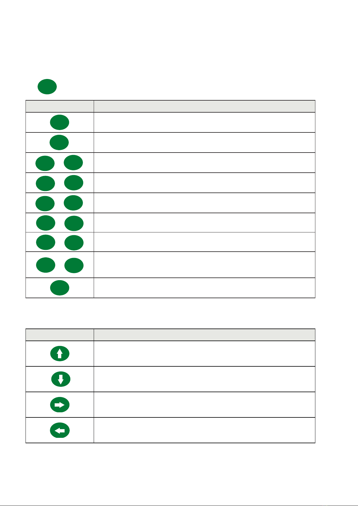
KEY FUNCTIONS DURING WEIGHT DISPLAY
ZERO Displayed value zeroing (gross weight).
TARE Automated Tare function
FUN + TARE Manual Tare function; this function is only accessible when no automated
tare is entered (*).
FUN + CLR Tare clear. (*)
FUN + SHF Switch displayed weight (net/gross). (*)
FUN + 1Access to set-point value set-up menu (*)
FUN + 2Cell channel switching. (*)
FUN + 3
Serial weight transmission via On Demand protocol. In case of metric ope-
ration, weight is saved in the alibi memory; weight and the weighing ID
code are transmitted via the On Demand protocol. (*)
PRG (Hold) Access to set-up menu.
*) Certain operating functions are performed by pressing the FUN key and an operating key in sequence
(e.g. the TARE key for manual tare set-up) The sequence should be completed within 2 seconds from
pressing the FUN key; during this time, the FUN status LED remains on.
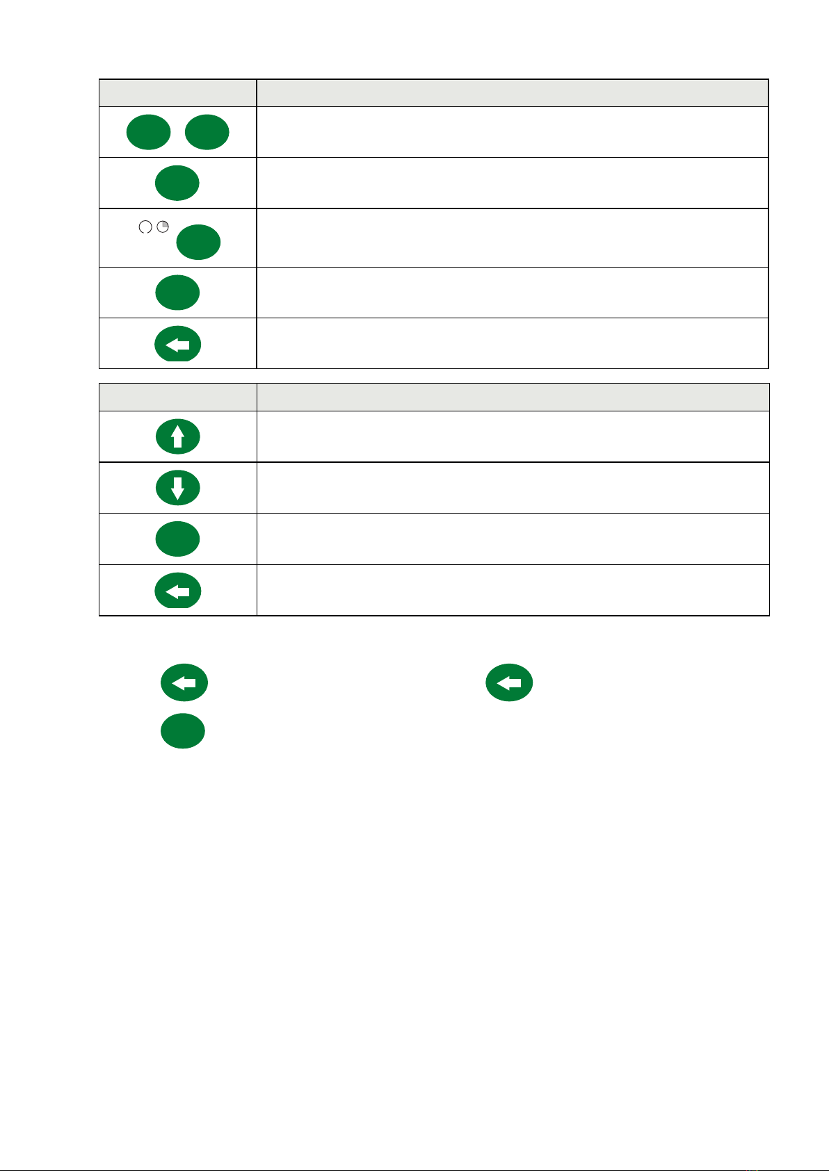
KEY FUNCTION WHEN BROWSING THROUGH THE SET-UP MENU
Selects the next menu.
Selects the previous menu.
Accesses the relevant sub-menu or set-up or confirms the selected parameter.
Exits from the set-up menu or returns to the higher level.
Page 13
KEY FUNCTION WHEN SETTING UP NUMERIC VALUES
0... 9Writes the selected value (a digit is added on the right).
CLR Delete last digit.
J
CLR (Holds) Resets set-up.
PRG Ends entry and saves the value
Exits without saving changes
KEY FUNCTION WHEN SETTING UP PROPOSED VALUES
Selects the higher value.
Selects the lower value.
PRG Confirms and saves the displayed value.
Exits without saving changes.
EXITING THE SET-UP MENU
Press the key to return to the main menu. Press the key again. “StorE?” is displayed.
Press the PRG key to save the entries and return to weight display.

Page 14
DISPLAY INFO
PAtH02
rEV. 04
When the unit is switched on, a display test is performed; the software ID and the
relevant version are then displayed. Such codes should be communicated in case of
support request.
When the set-up procedure is not under way, the display shows the measured weight in kg. The following
messages appear in certain conditions:
ERROR REPORTING
The following error codes may appear on the display in the operating mode.
Fixed message
O-L No load cell signal, or signal falls outside the mV/V measurement field.
- - - -
- -
Overload. The weight applied to the load cells exceeds the maximum capacity of the
weighing system by over 9 divisions.
- - - - - -Underload. This message appears when the measured weight is negative below the
displayable value.
Flashing message, alternating with the measured weight
no-CAL Weight calibration not performed, flashing message (alternating with the measured
weight).
Low.Uin Power supply too low in case of operation with power unit, flashing message (alternating
with the measured weight).
E.FibEr
Communication error with the S318 optical fiber interface board. This error is only
displayed in case of communication timeout and when the interface is enabled (ana-
logical output option enabled, COM3 protocol enabled, or COM4 protocol enabled).
No CoN Fieldbus network disconnected.
E-F.buS Fieldbus interface connection error.

Page 15
OPERATING FUNCTIONS
After calibration, the display shows the current weight when switched on next.
The possible operations that can be performed from the keyboard when weight is displayed are de-
scribed below.
KEY FUNCTIONS DURING WEIGHT DISPLAY
ZERO Display value zeroing (gross weight).
TARE Automated Tare function.
FUN + TARE Manual Tare function; this function is only accessible if no automated tare is
entered (*).
FUN + CLR Tare clear. (*)
FUN + SHF Switch displayed weight (net/gross). (*)
FUN + 1Access to set point value set-up menu (*)
FUN + 2Cell channel switching. (*)
FUN + 3
Serial weight transmission via On Demand Protocol. In case of metric opera-
tion, weight is saved in the alibi memory; weight and the weighing ID code
are transmitted via the On Demand protocol. (*)
PRG (Hold) Access to set-up menu.
(*) Some operating functions are performed by pressing the FUN key and an operation key in
sequence (for example, the TARE key to perform manual tare programming). The sequence must be com-
pleted within 2 seconds after pressing the FUN key, during this period the FUN status LED remains on.
ZEROING
The gross weight reset command is used to correct minor zero shifts of the weighing system during
regular operation. These zero shifts are usually due to thermal drifts or material residues accumulating
on the weighing system in time.
The gross weight reset command is not executed if any of the following conditions occurs:
• Unstable weight (with weight stability control enabled). In this case the reset command is only effec-
tive if weight is stabilized within 3 seconds, or if the weight stability control is disabled (“MOTION”
parameter = zero)
• Gross weight exceeding (in positive or negative terms) the number of divisions set in the “0 BAND”
parameter, when the self-zero set point is not set.
After the unit is switched off, the zero value acquired by zeroing gross weight is saved, in case of FREE
operating mode selected and AUTO ZERO function deactivated.
While gross weight can be zeroed multiple times, the number of divisions zeroed each time is summed
up. Therefore when the total exceeds the limit set in the “0 BAND” parameter, no zeroing can be per-
formed. In this case, Zero point calibration should be performed.

Page 16
Setting up the automated zero parameter upon switch-on (AUTO 0) reduces (or annuls, in case of
“AUTO 0” > “0 BAND”) the scope of action of the zero command.
AUTO-TARE
Autotare is not performed under the following conditions:
Unstable weight (the weight does not stabilize within 3 seconds of the reset command).
Gross weight equal to or greater than the maximum capacity of the weighing system.
After the unit is switched off, the AUTO TARE value is saved, only in case of FREE operating mode
selected and AUTO ZERO function deactivated.
ON-DEMAND TRANSMISSION
Serial transmission via the on-demand protocol is performed if the following conditions are in place:
• Stable weight (within 3 seconds from command).
• Weight changed by about 20 divisions since the last transmission performed (weight delta).
• Gross weight below maximum capacity.
• Only in case of METRIC operation, gross weight should be equal or lower than minimum weighing
(20 divisions).
• Only in case of METRIC operation, net and gross weight should be positive and not null.
WEIGHING SAVING
Weighing is saved in the alibi memory if the following conditions are in place:
• METRIC operation.
• Alibi memory option available in the unit.
• Stable weight (within 3 seconds from command).
• Weight changed by about 20 divisions since the last weighing performed (weight delta).
• Gross weight is equal to or lower than minimum weighing (20 divisions) and lower than maximum
capacity.
• Net and gross weight are positive and not null.
WEIGHT SET POINT SET-UP
The set-up value SET POINTs are compared against weight to drive the relevant logical output. The
comparator is selected in the logical input/output set-up procedure (see the corresponding section).
Press the FUN key to access Set point set-up; the FUN LED turns on; press key 1 within 2 seconds during
weight display.
Page 17
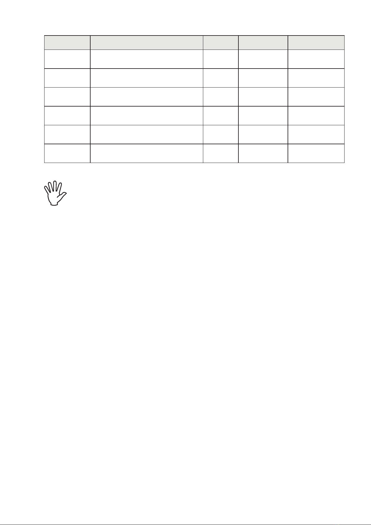
MESSAGGE DESCRIPTION DEFAULT RANGE FIELDBUS ADDR.
SEtP. 1 Sets the value of Setpoint 1 0 0÷Capacity 201(MSB)
202(LSB)
SEtP. 2 Sets the value of Setpoint 2 0 0÷Capacity 203 (MSB)
204 (LSB)
SEtP. 3 Sets the value of Setpoint 3 0 0÷Capacity 205 (MSB)
206 (LSB)
SEtP. 4 Sets the value of Setpoint 4 0 0÷Capacity 207 (MSB)
208 (LSB)
SEtP. 5 Sets the value of Setpoint 5 0 0÷Capacity 209 (MSB)
210 (LSB)
SEtP. 6 Sets the value of Setpoint 6 0 0÷Capacity 211 (MSB)
212 (LSB)
The set-up value set points are compared against weight to drive the relevant logical output.
The comparator is selected in the set point set-up procedure.
When weight cannot be measured or is out of scale, all the outputs are disabled (open or
closed contact according to MODE set-up, see the corresponding section).
In the set point set-up phase, both outputs are disabled. If the saved value set point is 0, the
relevant output is never enabled, whatever the selected set point set-up.

Page 18
CONFIGURATION
OVERVIEW
All the functions of the MC 315 can be enabled and adjusted by accessing a simple set-up menu, shown
on the following page. All the functions selected or enabled are saved even if the unit is switched off.
The MC 315 is pre-configured with default parameters. The “Default” values of each parameter are
shown on the following pages.
After first field installation, certain parameters need to be adjusted in order to ensure appropriate weight
display (theoretical calibration).
This feature can be requested upon purchasing the MC 315.
The values in the set-up menu can be adjusted using the front keys.
KEY FUNCTION WHILE SETTING UP THE MAIN MENU
Selects the next menu.
Selects the previous menu.
Accesses the relevant sub-menu or the set-up or confirmation of the selected
parameter.
Exits the set-up menu or returns to the higher level.
KEY FUNCTION WHILE SETTING UP PROPOSED VALUES
Selects the higher value.
Selects the lower value.
PRG Confirms and saves the displayed value.
Exits without saving changes.
KEY FUNCTION WHILE SETTING UP NUMERIC VALUES
0... 9Writes the selected value (a digit is added on the right).
CLR Delete the last digit.
J
CLR (Hold) Resets set-up.
PRG Ends entry and saves the value.
Exits without saving changes.
Table of contents
Other Pavone Systems Accessories manuals


