Pavone Systems MCT 1302 User manual

PAVONESYSTEMS
TECHNICAL MANUAL
MCT 1302 Touch screen batching version with RS232 serial, analog and Fieldbus
output Software version PW1507

Page II

Rel ID 19230101 SW 1.1
Page 1
TABLE OF CONTENTS
PRECAUTIONS.............................................................................................. Page 2
INTRODUCTION ........................................................................................... Page 3
TECHNICAL FEATURES................................................................................... Page 5
INSTALLATION .............................................................................................. Page 5
FRONT PANEL OF THE INSTRUMENT .............................................................. Page 16
MAIN SCREEN.............................................................................................. Page 17
INFO DISPLAY ............................................................................................... Page 19
OPERATING FUNCTIONS .............................................................................. Page 20
BATCHING RECIPES SELECTION ..................................................................... Page 22
MENU STRUCTURE ........................................................................................ Page 26
USER MENU ................................................................................................. Page 27
BATCHING PARAMETERS MENU..................................................................... Page 35
HARDWARE TEST MENU................................................................................ Page 39
INPUT/OUTPUT MENU .................................................................................. Page 40
ACCESSING THE SETUP................................................................................. Page 41
CALIBRATION................................................................................................ Page 42
ANALOG OUTPUT PARAMETERS..................................................................... Page 47
SERIAL OUTPUT PARAMETERS......................................................................... Page 48
WEIGHING PARAMETERS .............................................................................. Page 56
FILTER PARAMETERS ....................................................................................... Page 57
WORKING MODE PARAMETERS..................................................................... Page 59
TIME AND DATE MENU, DISPLAY CONTRAST MENU........................................ Page 62
UPLOAD/DOWNLOAD FUNCTION ................................................................ Page 63
SERIAL COMMUNICATION PROTOCOLS ........................................................ Page 64
FIELDBUS PROTOCOLS .................................................................................. Page 75
TROUBLESHOOTING ..................................................................................... Page 80

Page 2
PRECAUTIONS
READ THIS MANUAL BEFORE using or servicing the instrument.
FOLLOW these instructions carefully.
KEEP this manual for future use.
CAUTION
The purpose of this manual is to make the operator aware of the
texts and explanatory figures, the basic requirements and criteria
for the installation and correct use of the instrument.
Installation, maintenance and repair must carried be out only by
specialized personnel who must have read and understood this ma-
nual. “Specialized personnel” means personnel who, due to training
and professional experience, have been expressly authorized by the
System Safety Manager to perform the installation.
Supply the instrument with voltage whose value is within the limits
specified in the specifications.
It is the user’s responsibility to ensure that the installation complies
with the applicable regulations.
Any attempt to disassemble or modify the instrument not expressly
authorized will invalidate the warranty and relieve Pavone Sistemi
of any responsibility.
The installation and maintenance of this instrument should only be
permitted by qualified personnel.
Pay attention when checking, testing, and adjusting with the instru-
ment turned on.
Make the electrical connections in the absence of the power supply
voltage.
Failure to observe these precautions may result in danger.
DO NOT ALLOW untrained personnel to work, clean, inspect, repair
or tamper with this instrument.

Page 3
INTRODUCTION
The MCT 1302 is a touch screen weight indicator and batcher to be combined with load cells to meet
the industrial applications.
The instrument is installed in a frame in a slot having a drilling template of 138 x 53 mm and is secured
by means of the 2 tensioning screws supplied.
The MCT 1302 uses the RS232 serial port with ASCII protocols, to be connected to the PC, PLC and re-
mote units with a maximum distance of 15m beyond which it is necessary to use the RS422/RS485 serial
output that allows the connection also with MODBUS RTU protocol up to 32 addressable instruments.
The availability of the most popular field buses, as an alternative to the RS485 port, also allows inter-
facing the instrument with any supervision device currently offered by the market.
A USB 2.0 port is also available and facilitates interfacing with PCs using AN Utility Software available
in the kit.
6 digital inputs and 6 digital outputs configurable by Set-up are always available.
It is also possible to have the analog output in voltage or current even in the presence of the FIELDBUS.
Available versions:
• MCT 1302: weight indicator with RS232 serial output, USB, RS485. The supported protocols are
continuous Modbus RTU.
• MCT 1302/A: version with analog output.
• MCT 1302/PROFINET: weight indicator with RS232, USB and PROFINET serial output.
• MCT 1302/ETHERNET IP: weight indicator with RS232, USB and ETHERNET IP serial output.
• MCT 1302/ETHERCAT: weight indicator with RS232, USB and ETHERCAT serial output.
• MCT 1302/PROFIBUS: weight indicator with RS232, USB and PROFIBUS serial output.
The analog output can also be present with the FIELDBUS option
PAVONE SISTEMI
Page 4
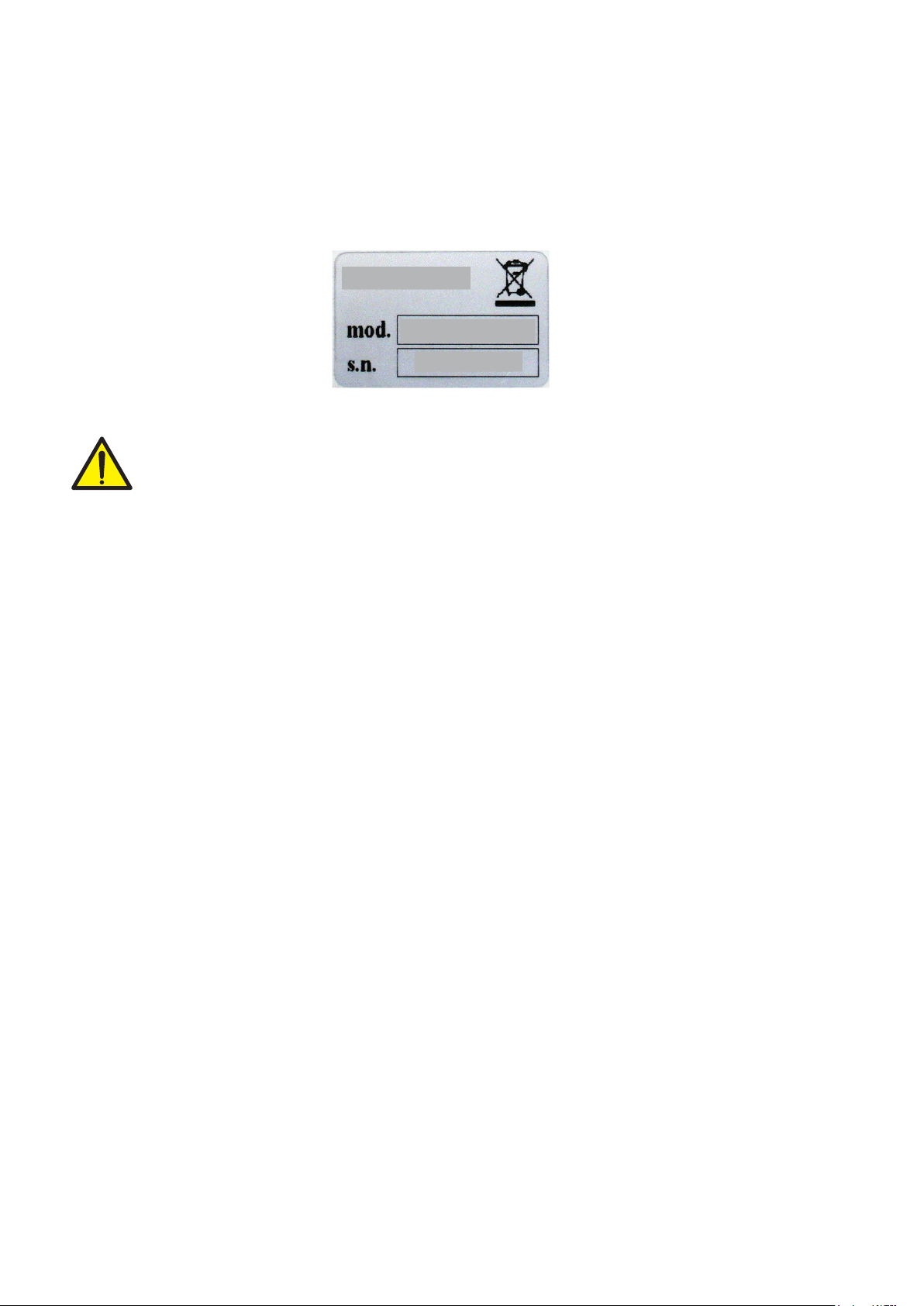
IDENTIFICATION PLATE OF THE INSTRUMENT
It is important to communicate this data, in case of request for information or indications concerning
the instrument, together with the program and version number, shown on the cover of the manual and
displayed when the instrument is switched on.
WARNINGS
The procedures listed below must be performed by specialized personnel.
All connections must be made when the instrument is switched off.

Page 5
TECHNICAL FEATURES
Power supply 18÷30 Vdc
Max. absorption 5 W
Isolation Class II
Installation category Cat. II
Working temperature -10°C ÷ +50°C (Max. humidity 85% without
condensation)
Storage temperature -20°C ÷ +70°C
Display Graphic 240x128 pixel LCD
Keyboard 4 wire resistive touch screen
Overall dimensions 150 x 95 x 26 mm (l x h x w) including terminal
blocks
150 x 95 x 56 mm (l x h x w) with FIELDBUS option
Drilling template: 138 x 82 mm
Assembly Panel Mount
Case material Aluminum
Connections Removable screw terminal blocks, 3.81 pitch.
Load cell power supply 5 Vdc/120 mA (max. 8 cells of 350 in parallel)
protected against short circuit
Input sensitivity 0.02 µV min.
Linearity < 0.01% of the full scale
Temperature drift < 0.001% of the full scale / C°
Internal resolution 24 bits
Displayed weight resolution Up to 999,999 divisions on the payload
Measuring range From -3.9 mV/V to +3.9 mV/V
Weight acquisition frequency 12 Hz - 1000 Hz
Digital filter Selectable 0,1 ÷ 250 Hz
Weight decimal number from 0 to 4 decimal places
Zero and Full Scale Calibration Automatic (theoretical) or executable from the
keyboard.
Logic outputs 6 opto-insulated (dry contact) max 24 Vdc / 100 mA
each
Logic inputs 6 opto-insulated at 24 Vdc PNP (external power
supply)
Serial port (#2) RS232C and RS422/485
Maximum cable length 15 m (RS232C) and 1000 m (RS422 and RS485)
Serial protocols ASCII, Modbus RTU
Baud rate 1200, 2400, 4800, 9600, 19200, 38400, 57600,
115200 selectable
USB port: compliant with USB 2.0; speed up to 12 Mbps
Analog output (optional) 16-bit opto-insulated
Voltage: 0 ÷ 5/10 V (R min 10 KOhm),
Current: 0/4 ÷ 20 mA (R max 300 Ohm)
Analog output calibration From the keyboard
Linearity <0.02% FS
Thermal drift 0.001% FS/°C
Microcontroller: ARM Cortex M0 + 32 bit, 256 KB Flash
reprogrammable on-board from USB.
Data memory 64 Kbytes expandable up to 1024 Kbytes
Fieldbus (as an alternative to RS485) PROFINET, ETHERNET IP, ETHERCAT, PROFIBUS
Compliance with Standards EN61000-6-2, EN61000-6-3, EN61010-1,
EN45501

Rmax 2
82±1
138±1
94
149
80
136
52
5.0
20
30
149
94
MCT 1302
Page 6
INSTALLATION
GENERAL INFORMATION
The MCT 1302 is a compact panel mounting instrument made of aluminum.
The instrument is installed in a panel in a slot with a drilling template of 138 x 82 mm and is secured
by means of the 2 tensioning screws supplied.
The MCT 1302 must not be immersed in water, subjected to jets of water and cleaned or washed with
solvents.
Do not expose to heat or direct sunlight.
Do not install the instrument near power equipment (motors, inverters, contactors, etc.) or near devices
that do not comply with CE regulations for electromagnetic compatibility.
The connection cable for the load cells must have a maximum length of 140 m/mm².
The RS232 serial line must have a maximum length of 15 meters (EIA RS-232-C standards).
The warnings given on the connection of the individual peripheral devices must be observed.
OVERALL DIMENSIONS
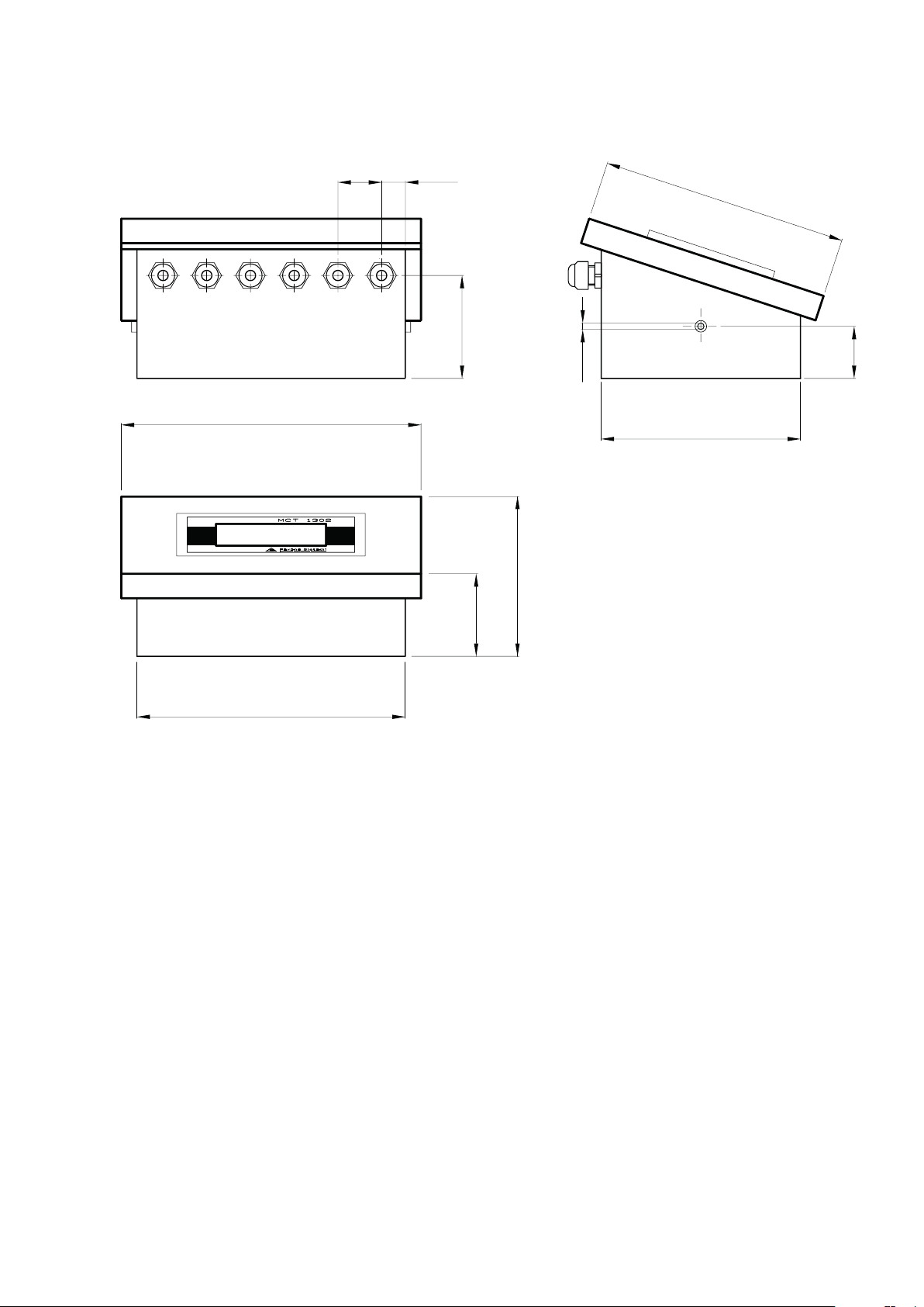
237
146
202
32
169
20
68
37
M4
113
62
Page 7
MCT S 1302 DIMENSIONS
+
-
10÷30 Vdc
GND
123456789
1 2 3 4 5 6 7 8 9 15 16 17 18 19 20 21 22 2310 11 12 13 14 24 25 26
1 2 3 4 5 6 7 8 9 10 11 12 13 14
In 1
In 2
In 3
In 4
In 5
In 6
I Com
Out 1
Out 2
Out 3
Out 4
Out 5
Out 6
O Com
-Sig2
+Sig2
+Sig1
-Sig1
-Sense
+Sense
+Exc
-Exc
Shield
123456789
N.6 INPUTS N.6 OUTPUTS
LOAD CELL 1LC2
&
2008/ 9 5/ EC
USB
Device
17 18 19 20 21 22 23 24 25 26
TXD
RXD
SGND
S I/O +
S I/O -
AGND
Vout+
Iout+
+Vdc
GND
SERIAL Power
Supply
AN.
+
-
EXC-
EXC+
SENSE+
SENSE-
SIG-
SIG+
SHIELD
OUTPUTS
30 Vdc
100 mA Max
OUTPUT 2
OUTPUT 1
COM. OUTPUT
V+ (10 kΩ min)
Ana-
mA+ (300 Ω max)
RS485
INPUT 2
INPUT 3
INPUT 4
INPUT 5
INPUT 6
COM. INPUT
INPUT 1
OUTPUT 3
OUTPUT 4
OUTPUT 5
OUTPUT 6
TX-/RX-
TX+/RX+
ANALOG
OUTPUT
24 Vdc
100 mA Max
RS232
RXD
TXD
SGND
OPTIONAL
OUTPUT
OPTIONAL ETHERNET
FIELDBUS
+
-
25 +Vdc
Power Supply
24 Vdc
26 GND
Screw
Page 8
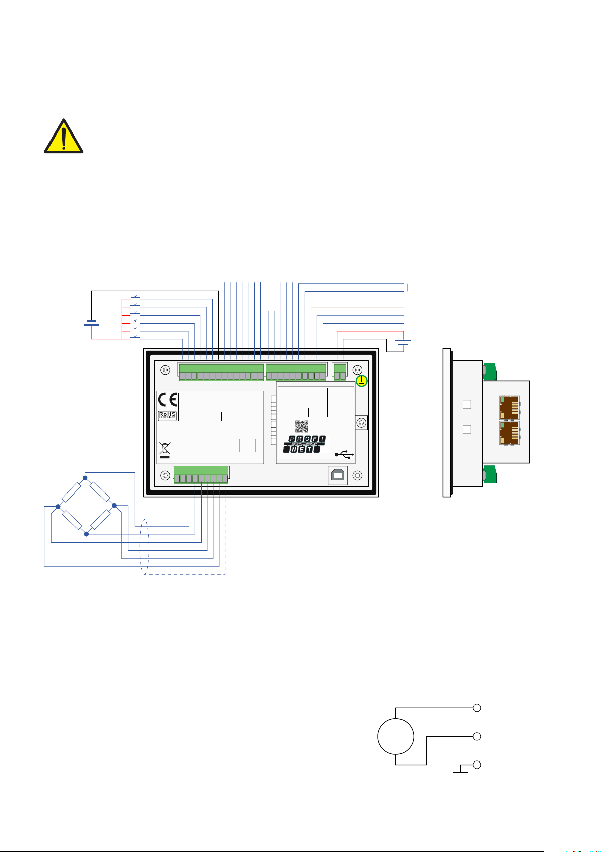
ELECTRICAL INSTALLATION
The MCT 1302 instrument uses for the electrical connection of the 3.81 mm removable screw terminal
blocks. The load cell cable must be shielded and channeled away from power cables to avoid elec-
tromagnetic interference.
The field wiring of the instrument must be suitable for the environment in which it will be used
and must comply with all national regulations.
A switch or disconnector must be included in the electrical system.
The switch must be close to the instrument and easily reachable by the operator.
The switch must be marked as a device to stop the machine.
The switch or circuit breaker used as a disconnecting device must comply with the applicable require-
ments of IEC 60947-1 and IEC 60947-3.
WARNING
Disconnect the power supply to the instrument before making electrical connections.
POWER SUPPLY OF THE INSTRUMENT
The instrument is powered through terminals 25 and 26. The power cable must be routed separately
from other cables.
The electric zero (terminal 26) is connected to the metal case. Connect
the terminal 26, in addition to the GND of the power supply, also
on the ground using the screw near the power terminals.
Supply voltage: 18÷30 Vdc, max 5W

3 +Signal
4 -Signal
5 -Sense
6 +Sense
7 +Exc.
8 -Exc
9 Shield
JBOX
+Exc-Exc
+Sig
-Sig
+EXC
-EXC
+SGN
-SGN
SHD
+EXC
-EXC
+SGN
-SGN
SHD
+EXC
-EXC
+SGN
-SGN
SHD
+EXC
-EXC
+SGN
-SGN
SHD
25 PIN CONNECTOR
+SGN
-ALM
+ALM
-SGN
+SNS
-SNS
+ALM
-ALM
+SGN
-SGN
+ALM
-ALM
+SGN
-SGN
+ALM
-ALM
+SGN
-SGN
+ALM
-ALM
+SGN
-SGN
SCH
SCH
SCH
SCH
SCH
2
3
6
1
5
4
7
1
2
3
4
5
1
2
3
4
5
1
2
3
4
5
1
2
3
4
5
J-BOX CGS4
FIELDBUS
MCT 1302
TX+/RX+
TX-/RX-
-SENSE
+SENSE
SHIELD
S I/O+
S I/O-
-SIG1
+SIG1
O COM
S.GND
Iout+
Vout+
I COM
AGND
OUT2
-EXC
+EXC
OUT1
OUT3
OUT4
OUT5
OUT6
IN3
IN4
IN5
IN2
IN1
RXD
TXD
24V
IN6
04
03
08
05
06
07
19
18
17
25
26
09
24
23
22
14
10
11
12
13
15
16
20
21
9
1
2
7
+
-
8
3
4
5
6
+24V
Page 9
LOAD CELL CONNECTION
The load cell cable must not be routed with other cables, but must follow its own path.
Any cable extension connections must be carefully shielded, respecting the color code and using the
cable of the type supplied by the manufacturer. The extension connections must be made by welding,
or through support terminal blocks or through the junction box supplied separately.
Up to a maximum of 8 350 ohm load cells in parallel can be connected to the instrument. The supply
voltage of the load cells is 5 Vdc and is protected by a temporary short circuit.
The measuring range of the instrument involves the use of load cells with sensitivity up to 3.9 mV/V.
The load cell cable must be connected to terminals 3 to 9. In the case of a 4-wire cell cable, jumper
the terminals 5 to 8 and 6 to 7.
Connect the load cell cable shield to terminal 9.
In case of use of two or more load cells, use appropriate junction boxes (CEM4/C or CSG4/C) of
which the connection is shown below.
1 In1
2 In2
3 In3
4 In4
5 In5.
6 In6
7 I Comm
+
-
24 Vdc
8 Out 1
9 Out 2
10 Out 3
11 Out 4
12 Out 5.
13 Out 6
14 O Comm
+
-
24 Vdc
Page 10
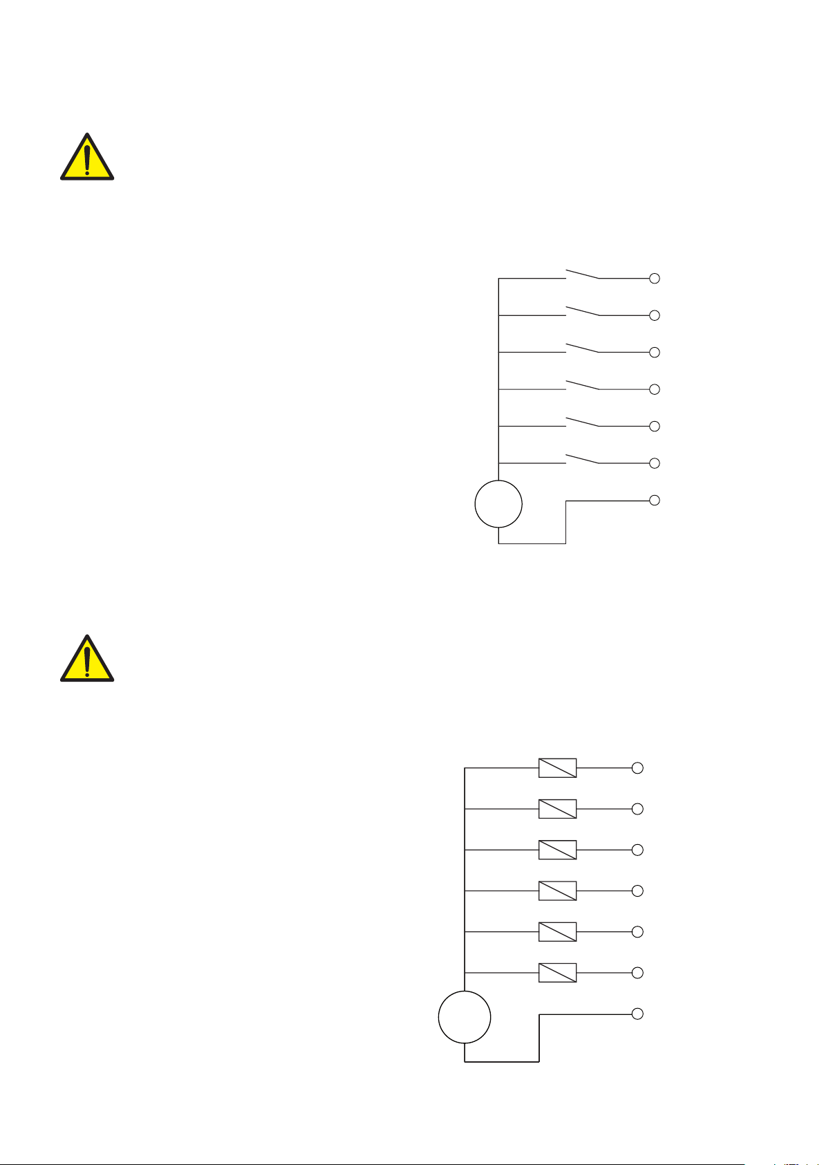
LOGIC INPUTS
The logic inputs are insulated from the instrument through optocouplers.
The connection cables of the logic inputs must not be channeled with power cables.
Use a shorter connection cable as possible.
To activate a logic input, it must be brought to the positive of a 24Vdc power supply while
the common item must be connected to its negative. The function of the inputs is established
in the relevant Setup menu.
LOGIC OUTPUTS
The 6 logic outputs are of the Photorelay (dry contact) type with a common item. The capacity of each
contact is 100 mA / 30Vdc. By enabling the output, the contact closes (NA contact).
The environment where the equipment is installed can normally be subject to strong magnetic
fields and electrical noise caused by the machinery present, so it is advisable to implement
the usual precautions in order to avoid that these affect the typical signals of a precision
electronic equipment. (filters on contactor, diodes on 24 Vdc relays, etc.)
The connection of the outputs is shown below

17 TX
18 RX
RS232
INTERFACE
RX
TX
19 GNDGND
MCT 1302
20 S I/O+
21 S I/O-
External
I/O Board
19
20
MCT 1302
Page 11
CONNECTION WITH ADDITIONAL INPUTS/OUTPUTS BOARD
In applications where additional inputs/outputs are required, optional I/O boards can be connected
using the dedicated serial connection.
To make the connection, use a shielded cable, taking care to connect the screen to ground at only one
of the two ends. If the cable has more conductors than those used, connect the free wires to the screen.
SERIAL RS232
COMMUNICATION
The serial connection cable must have a maximum length of 15 meters (EIA RS-232-C standards), beyond
which it is necessary to adopt the RS485 interface with which the instrument is equipped.
The cable must not be channeled with other cables (i.e. outputs connected to contactors or
power cables), but must possibly follow its own path.
The PC used for the connection must comply with the EN 60950 standard.
The RS232 serial port is normally used for PC, printer and repeater connections.
To make the serial connection, use a suitable shielded cable, taking care to connect the screen to ground
at only one of the two ends.
The serial connection cable must have a maximum length of 100 meters. The cable must
not be channeled with other cables, but must possibly follow its own path

15 TX+/RX+
16 TX-/RX-
USER
RS485
INTERFACE
TX+/RX+
TX-/RX-
MCT 1302
24 +mA
23 +Volt
ANALOG
INTERFECE
CURRENT
VOLTAGE
22 GNDGND
MCT 1302
Page 12
RS485
Through serial RS485 interface, it is possible to make serial connections for long distances (up to 1000 m).
The RS485 serial connection is of the 2-wire type, and allows to connect up to 32 instruments to a
single MASTER unit (personal computer, PLC, etc.) using a twisted and shielded cable, taking care to
connect the screen to the ground at only one of the two ends.
The cable must not be channeled with other cables (i.e. outputs connected to contactors or power ca-
bles), but must possibly follow its own path.
The PC used for the connection must comply with the EN 60950 standard.
NOTE: If there is a fieldbus, the RS485 is not available.
ANALOG OUTPUT (OPTIONAL)
The instrument provides an opto-insulated analog output in current and/or voltage.
Features:
• Analog voltage output: range from 0 to 10 Volt or from 0 to 5 Volt, minimum load 10K
• Analog current output: range from 0 to 20 mA or from 4 to 20 mA. The maximum load is 300.
To make the connection, use a shielded cable, taking care to connect the screen to ground at only one
of the two ends.
The analog sending can be sensitive to electromagnetic disturbances, it is therefore recommended that
the cables are as short as possible and that they follow their own path.
Warning: do not connect the analog output to active devices.

Page 13
USB DEVICE (SPECIFICATION 2.0 COMPLIANT, FULL-SPEED 12 MBPS)
Use this communication port to directly interface a PC via a USB port.
Use a standard USB cable for the connection.
To connect the instrument via the USB device port, the appropriate driver for the operating system used
must be installed on the PC. For the installation, follow the specific instructions.
FIELDBUS CONNECTIONS
As an alternative to the RS485 serial port, some of the most popular fieldbuses are available. Only
one fieldbus can be used, which must be specified when ordering.
ETHERNET CONNECTION
In the lower left part of the instrument there is an RJ45 connector for Ethernet network.
Features:
10 Mbps transmission speed
Network compatible with 10/100/1000 Base-T networks
Ethernet TCP, Modbus / TCP, UDP, IP, ICMP, ARP protocols
TCP server communication mode
Indicator LEDs (2) Ethernet line presence and communication/diagnostics
Buffer size 256 bytes
Connection Timeout Min. 30 seconds - Max. 90 seconds
Link Timeout (cable disconnected) 30 seconds
PIN DESCRIPTION
1 TX+
2 TX-
3 RX+
4
5
6 RX-
7
8
To connect to the MASTER, use an Ethernet twisted pair cable with the relevant RJ45 connector.
• The RJ45 Ethernet connection cable has a variable maximum length depending on the type of cable.
A common shielded Cat5 cable can have a maximum length of about 180 m.
• It is possible to connect the ethernet communication port directly to the PC, without switching from
other network devices (routers, switches, hubs, lan-bridges or other), but special RJ45 cables, called
“crossovers”, must be used.
• Usually the cables are “direct”, and allow the connection to network devices such as routers or hubs,
but not to directly connect two PCs (although currently there are network cards with auto-sensing
technology, which recognize the type of cable and the type of connection, allowing direct PC-PC
connections even using non-crossover cables).
• The following page shows the diagrams of the two types of cables mentioned above and the related
connection diagram.

1 2 3 4 5 6 7 8
1 2 3 4 5 6 7 8
TX+
RX+
RX-
TX-
TX+
RX+
RX-
TX-
1TX+
2TX-
3RX+
6RX-
1 RX+
2 RX-
3 TX+
6 TX-
DIRECT ETHERNET CABLE
1 2 3 4 5 6 7 8
1 2 3 4 5 6 7 8
TX+
RX+
RX-
TX-
RX+
TX+
TX-
RX-
1TX+
2TX-
3RX+
6RX-
1 TX+
2 TX-
3 RX+
6 RX-
CROSSOVER ETHERNET CABLE
Page 14
ETHERNET/IP CONNECTION
Ethernet/IP is a real-time industrial protocol based on the Ethernet network.
There are 2 RJ45 connectors to allow the connection of several instruments under the same network.
Refer to the description above for connection notes and warnings.
Features:
10 and 100 Mbit operations, Full and Half Duplex
Modbus-TCP server
Up to 128 bytes of fieldbus I/O in every direction.
PROFINET CONNECTION
There are 2 RJ45 connectors to allow the connection of several instruments under the same network.
Refer to the previous page for connection notes and warnings.
Features:
PROFINET IO Real Time (RT) communications
Modbus-TCP server
Up to 128 bytes of fieldbus I/O in every direction.
ETHERCAT CONNECTION
EtherCAT is a real-time industrial protocol based on the Ethernet network.
The EtherCAT protocol requires that the RJ45 connectors have the function of IN and OUT.
By putting several MCT 1302 instruments in series, the MASTER will be connected to the IN connector
of the first MCT 1302 whose OUT connector will connect to the IN connector of the next, etc.
Refer to the previous page for connection notes and warnings.
3
8
15
9 6
B_LINE
A_LINE
Page 15
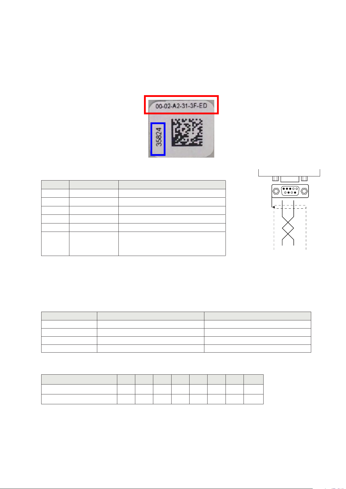
MAC ADDRESS IN THE INSTRUMENTS WITH ETHERNET INDUSTRIAL FIELDBUS.
The instruments that mount Hilscher modules with Industrial Ethernet protocol (Profinet, EthernetIP, Ether-
cat, etc.) have a label under the connectors, as shown below.
This label shows the MAC Address of the module (red box), an identification number of the module
(blue box) and a QR code that contains the MAC Address. The latter can be read with a smartphone
using a QR reading app i.e., on the Google Play Store, “QR Code Reader”).
PROFIBUS CONNECTION
Pin Signal Description
3 B line +RxD/+TxD, level RS485
4RTS Request to send
5 GND Ground (insulated)
6 + 5V Bus Output +5V end (insulated)
8 A line -RxD/-TxD, level RS485
Housing Cable shield
Internally connected to the protective
ground according to Profibus
specifications
To connect to the Profibus MASTER, use a standard Profibus cable. The typical impedance of the cable
should be between 100 and 130 Ohm (f > 100 kHz). The cable capacity (measured between conductor
and conductor) should be less than 60 pF/meter and the minimum conductor cross-section should not
be less than 0.22 mm2.
In a Profibus-DP network, both type A and type B cables can be used, depending on the required per-
formance. The following table summarizes the characteristics of the cable to be used:
Feature Type A cable Type B cable
Impedance 135 to 165 ohm (f = 3÷20 MHz) 100 to 300 ohm (f >100 kHz)
Capacity < 30 pF/m < 60 pF/m
Resistor < 110 ohm/km -
Conductor section > 0.34 mm2> 0.22 mm2
The following table shows the maximum length of the line with type A cable and with type B cable
according to the different communication speeds required:
Baudrate (kbit/s) 9.6 19.2 187.5 500 1500 3000 6000 12000
Length (m) of the type A cable 1200 1200 1000 400 200 100 100 100
Length (m) of the type B cable 1200 1200 600 200 - - - -
For reliable operation of the fieldbus, a line terminator should be used at both ends.
In case of multiple MCT 1302 instruments, use the line end only on an instrument.
For the setup of the board, the GSD file (hms_1810.gsd) is available and must be installed in the master.

149
94
MCT 1302
MCT 1302 - DOSAGGIO
PW1507 Rev. 0.9
Page 16
FRONT PANEL OF THE INSTRUMENT
The MCT 1302 is a touch screen instrument dedicated to batching applications.
The main operating characteristics are:
• Programmable recipes, standard - 100 recipes of 20 steps. With Alibi memory option - 1000
recipes with 20 steps.
• 50 programmable activities.
• Management of 38 configurable outputs (6 internal outputs to the instrument plus 8 outputs for each
connected I/O module; maximum 4 modules that can be connected to the instrument). Depending
on the type of activity, up to 2 outputs can be selected.
• Coarse and Fine batching control, tolerance control of the dosed weight and lack of product.
• Automatic repetition of the batching cycles.
• Management of the batched totals by activity and recipe.
The setup parameters are easily accessible and modifiable through the use of the function keys that
from time to time appear on the display used to select, edit, confirm and save the new settings.
DISPLAY
In the operating mode the display shows all the information necessary for a complete control of the
system. According to the various programming procedures, the display is used for programming the
parameters to be entered in the memory, i.e. messages indicating the type of operation being carried
out and therefore helping the operator in the management and programming of the instrument.
POWER UP OF THE INSTRUMENT
When switched on, the display temporarily shows an introductory mask, which shows the firmware
code and the version number. After a few seconds, the main screen is displayed, from which all the
instrument operations can be accessed.
Page 17
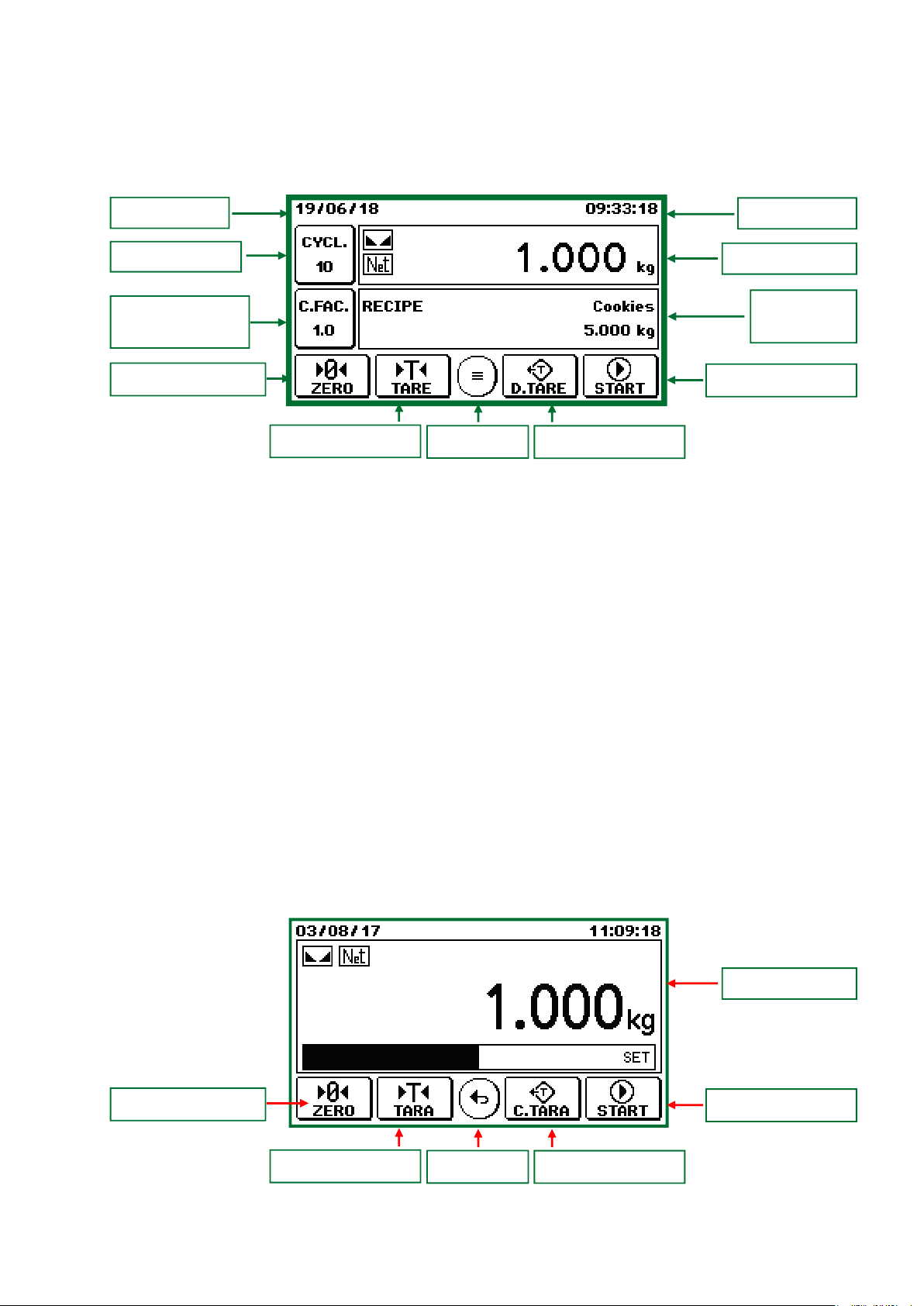
MAIN SCREEN
From this screen it is possible to access all the operational and programming functions of the instrument,
following the indicated commands.
Date
The display mode of the main screen can be selected using the appropriate parameter in the “Opera-
ting Mode” menu:
• “Standard” main screen, in which all the quadrants are displayed (weight, recipe selection, cycle
setting, set correction factor setting, batching information).
• Main screen “weight only”, in which only the weight dial is displayed. In this case the weight value
is displayed with a larger size than the standard display. Moreover, in case of batch in progress,
a bargraph is displayed, which represents the net weight batched in relation to the set value.
The “weight only” main screen is activated under the following conditions:
• After 5 seconds from switching on the instrument.
• After 5 seconds from the start of the batch.
To temporarily restore the “standard” main screen, press on the weight value. After 5 seconds the
“weight only” main screen appears again.
The functions of the operation keys (F1, F2, F3 and F4) can be programmed using the appropriate
parameters in the “Operating Mode” menu.
All the keys on the main screen can be locked using the appropriate parameters in the “Operating
Mode” menu.
Time
Batching cycles Weight quadrant
Recipe
quadrant
Recipe correction
factor
F1 Operation key
F2 Operation key F3 Operation key
F4 Operation key
Menu key
Weight quadrant
F1 Operation key
F2 Operation key F3 Operation key
F4 Operation key
Menu key

Page 18
OPERATION KEYS
Access to the parameter programming menu.
Press in the weight display dial to switch the weight display (net, gross).
Access to the recipe selection screen.
Press in the setting screen for the number of batching cycles.
Access to the recipe correction factor setting screen. The correction value
change creates the printout of the recipe with the recalculated batching
set point. The value is expressed in percentage or weight (Parameter
"CORRECTION MODE" - page 22)
Semi-automatic Zero Command.
Tare Command.
Deleting Tare Command.
Start batching command.
Weight Print Command
Table of contents
Other Pavone Systems Accessories manuals


Popular Accessories manuals by other brands

SImx
SImx LHT0244 installation instructions

Chef's Choice
Chef's Choice Trizor XV 15 instructions

URBAN VITAMIN
URBAN VITAMIN PASADENA PD user manual

Schüco
Schüco FWS 114 Technical manual

XLT Ovens
XLT Ovens XLT TS3-S Standard Series Installation & operation manual

URBAN VITAMIN
URBAN VITAMIN ALAMEDA user manual


