Instructions for Alphalux SureScan™ Sensor
Part Number: ALXPIR
10A, 240V, 10 Metre Range
INTRODUCTION:
The Alphalux range of sensors and oodlights that includes the SureScan™ have been designed in
consultation with our customer base of installers. More than 15 years of experience in light ttings and
sensors have combined to create a comprehensive range of high quality solutions.
The Alphalux SureScan™ includes the following features:
• Maximum 10 Amp high power output to control multiple loads.
• High quality passive infrared (PIR) sensing circuit used to prevent nuisance switching.
• Timer, light adjustment and distance sensitivity controls.
• Full sensor head direction adjustment.
• Screw mount lock nut to prevent post-installation movement.
• Three mounting base entry ports for exible sensor head positioning.
• 20mm threaded mounting base suits common conduit and tting entries.
• O-ring sealed to maintain IP rating and exclude water and dust.
• Unit base ts typical mounting boxes with 84mm mounting centres.
• Rubber seals supplied for xing to at mounting surfaces.
• Includes insulated connectors for faster and more convenient installation.
• Heavy-duty UV stabilised plastic.
• Includes matching mounting box for additional termination space and easy tment.
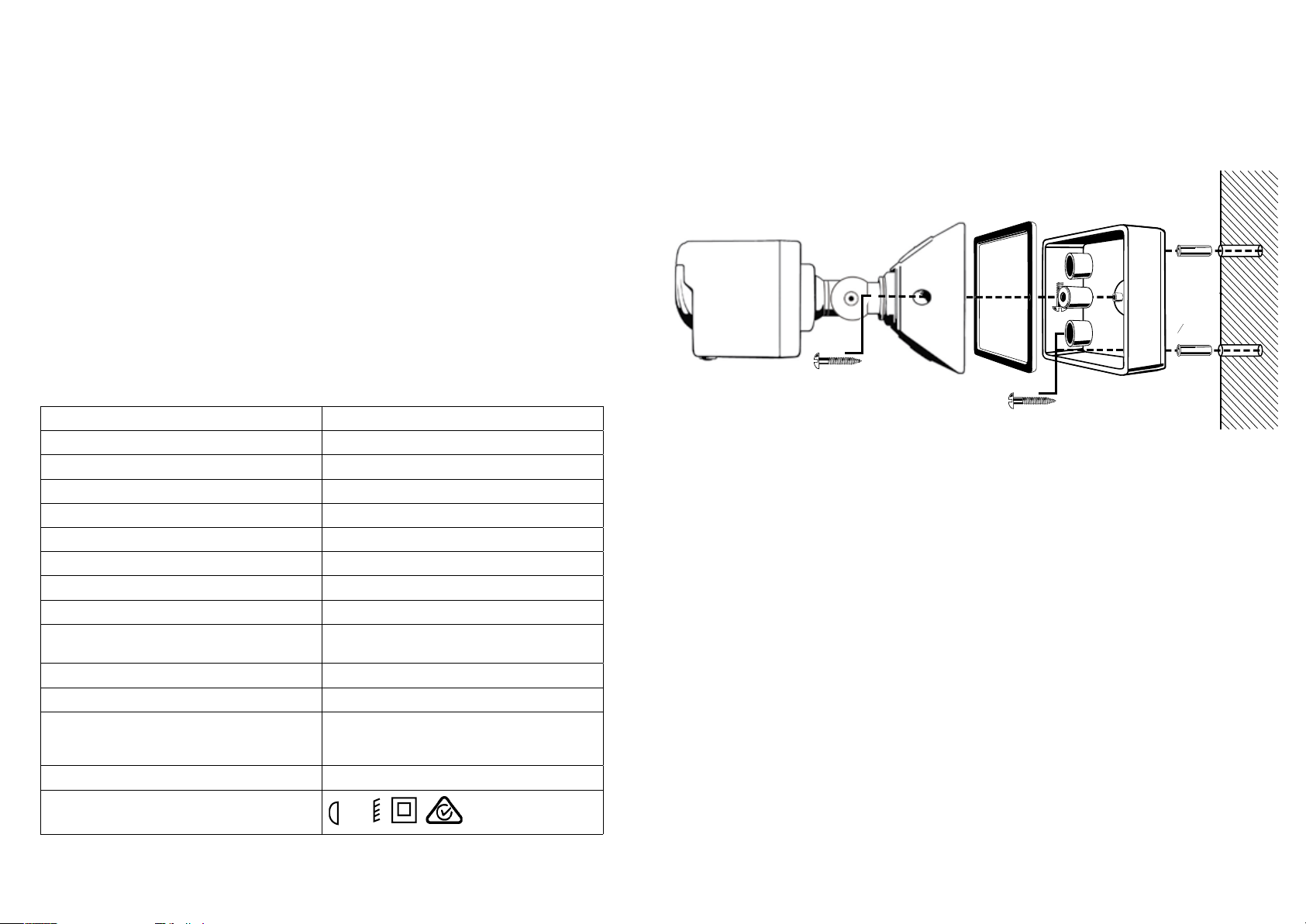
INSTALLATION:
Note: This product must be installed by a qualied electrician and in accordance with the appropriate
wiring rules and regulations.
Ensure that all electrical supplies are isolated at the switchboard before installation or maintenance of
these ttings takes place.
FINDING THE BEST LOCATION:
The position of passive infrared sensors (PIR) is critical to their performance and vital in reducing
nuisance triggering. The following guidelines should be followed to maximize the performance of the
units:
• The unit should be a minimum of 2.4 metres above the area that is being monitored.
• For best performance the path of motion should be across the eld of vision of the sensor.
Head-on detection is the most unreliable method of sensing.(Refer to diagram)
• To avoid incorrect tripping of sensor, do not mount close to electrical devices which produce
electrical interference (RFI noise). Avoid uorescent ttings, ceiling fans, remote control doors etc.
Older versions of these devices in particular.
The warranty for this electrical product covers defects of materials and workmanship for one year from the date of
purchase, provided that the product is used according to The L&H Group recommendation and is within the limits
specied. The L&H Group will at its own option make good, replace or provide credit for any product manufactured
or supplied by it, which proves to be defective within the limits set out above provided that no repairs, alterations or
modications to the product have been undertaken or attempted,other than by the company or its authorised agents.
Any defective product should be returned to your original place of purchase or sent Postage Paid to The L&H Group
at the address shown below. The purchase receipt must be returned with the product to obtain warranty repair or
replacement. This warranty is in addition to any guarantee implied by Federal or State legislation.
PROOF OF PURCHASE
• Please retain your purchase receipt for all service or warranty claims.
• Complete details of your purchase in the section below for your own reference.
Date of purchase
Type of Product / Model No
Your Name
Your Address
Branch
Distributed by:
L&H Group
456 Lower Heidelberg Road
Heidelberg VIC 3084
The L&H Group has a policy of continual improvement throughout their product range,
the unit contained may differ slightly from the unit illustrated on the pack.
For product enquiries contact our Customer Service Centre: 1300 300 254
Form No: 4508/MKT 03/11 R
Problem Probable Cause Suggested Solution
Lights will not activate when there is
movement in the detection area
Power failure or power not switched on Check connections, fuse and switches
Faulty globe/s Replace globe/s
Controls incorrectly set Change direction angle, adjust
sensitivity
Sensor aimed incorrectly Change position and/or direction of
sensor
Incorrectly wired Re-check all wiring
Light turns on for no apparent reason Air conditioner or heater
vents close to sensor
Change position and/or direction of
sensor
Animals or birds crossing detection area Probably unavoidable.
Change direction of sensor, adjust
sensitivity
Reective objects in detection area Change direction of sensor and
consider repositioning
Electrical interference on the same
circuit
Check for arcing switches and replace
noisy uorescent tubes and/or starters.
Consider connecting the unit to an
alternative circuit
Lights will not turn off after set time has
elapsed
Lights are in manual mode not
automatic
Turn lights off for at least 10 seconds
then turn them on again to return
sensor to automatic mode
Wiring is not correct Recheck the wiring
TROUBLE SHOOTING GUIDE: