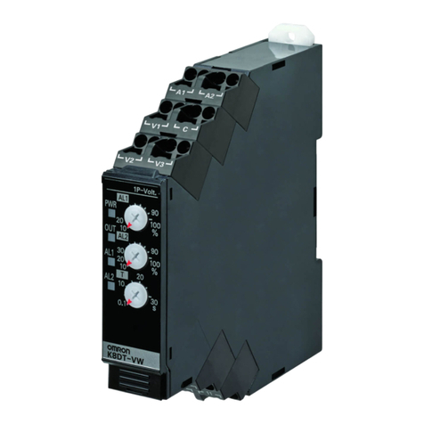
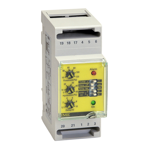
Pavotek DEMA DigiLine 400 Series User manual

DEMA Role San. ve Tic. A. S. DEMA DigiLine 400 Series Protection Relays Page 1 of 11
Quick Start Guide V1.0

DEMA Role San. ve Tic. A. S. DEMA DigiLine 400 Series Protection Relays Page 2 of 11
Quick Start Guide V1.0
Versions
Rev.
No
Comp. Relay SW
Version
Cause of Revision
Committer
Date
V1.0
1.1.9.2 and later
First Publication
Cihangir ODABAŞ
03.04.2019

DEMA Role San. ve Tic. A. S. DEMA DigiLine 400 Series Protection Relays Page 3 of 11
Quick Start Guide V1.0
1Contents
2Power Up the Relay............................................................................................................................. 4
3Start Communicating with the Relay .................................................................................................. 5
4Configure the Relay with DigiConnect 400 ......................................................................................... 7
5Configure the Relay with WebServer................................................................................................ 10

DEMA Role San. ve Tic. A. S. DEMA DigiLine 400 Series Protection Relays Page 4 of 11
Quick Start Guide V1.0
2Power Up the Relay
DigiLine 400 Series have one of the easy to use power up sequence. The relay has wide range of input voltage
over same input pins. Voltage specifications are listed below;
Auxiliary Power Supply Specifications
Description
Value
Nominal auxiliary voltage
(48-240) Vac, (24-240) Vdc
Operating range of auxiliary voltage
(36-264) Vac, (22-264) Vdc
Nominal frequency for AC voltage
50 / 60 Hz
To power up the relay, proper voltage needs to be supplied to the rear connectors. To identify which ports should
be used, please follow connector plan on the side of the relay (Figure 1).
Power pins are on the X03 Connector with numbers 50-51.
52 is used for chassis, but not absolute must.
Figure 1: Relay Rear Side

DEMA Role San. ve Tic. A. S. DEMA DigiLine 400 Series Protection Relays Page 5 of 11
Quick Start Guide V1.0
3Start Communicating with the Relay
DigiLine 400 Series offers easy access to user with different interfaces. Interfaces let user use either related
Communication Protocols, DigiConnect 400 PC Config Tool or Webserver. Available ethernet interfaces are listed
below;
Ethernet Interfaces
Interface
Type
Data rate
IP Address
Front
Standard Ethernet (CAT 5
with RJ-45)
100 Mbits/s
Fixed - 192.168.2.215
Rear
2 ports Copper (Standard
Ethernet CAT 5 with RJ-45)
2 port Fiber Optics
100 Mbits/s
IP is configurable.
4 port shares same IP.
Ports are bridged.
Front port Ethernet has fixed IP (192.168.2.215) to supply easy and fast communication through all DigiLine 400
series.
To change Rear Port IP address, please follow the instructions below;
Enter the menu of ethernet settings on the device GUI. Follow the menus accordingly (Menu > Configuration >
Eth Interface Settings). Enter “Setting” button the open Rear Port Settings (Figure 2). IP, Netmask and Gateway
could be selected via corresponding buttons. Link status could be observed status bar.
Figure 2: Ethernet Settings Menu and Rear Port Settings

DEMA Role San. ve Tic. A. S. DEMA DigiLine 400 Series Protection Relays Page 6 of 11
Quick Start Guide V1.0
After choosing which port is used, connect it with your PC. After connection is established, network settings on
computer should be adjusted. Computer should be on the same network with the relay. Please follow the
instructions below;
Enter computers ‘Control Panel > Network and Internet > Network Connections’ or ‘Change adapter options’ of
ethernet ports (Figure 3). Right click Ethernet and select ‘Properties’ (Figure 4). Open ‘Internet Protocol Version
4 (TCP/IPv4)’ properties. Give an IP address to your PC with careful of below warnings.
Warning 1: Do not give the same IP to your PC with relays.
Warning 2: PC’s IP should be on same subnet with relays.
Same subnet means first three region of IP addresses should be matched. For example, if front port
(192.168.2.215) of the Relay is connected to PC, PC’s IP should be 192.168.2.XXX. On Figure 4, it is given as an
example with 192.168.2.100.
Figure 3: Network Connections
Figure 4: Ethernet and TCP/IPv4 Properties

DEMA Role San. ve Tic. A. S. DEMA DigiLine 400 Series Protection Relays Page 7 of 11
Quick Start Guide V1.0
4Configure the Relay with DigiConnect 400
After communication configuration is enabled with Step 3, settings could be managed with DigiConnect400 PC
Config Tool. It can be downloaded over https://www.demarole.com.tr/en/product/400-series-protection-relays
address.
DigiConnect 400 is simple and easy to use tool which manages configuration of multiple relays on same project
tree. DigiConnect can read/write settings to connected relays. Inside projects, offline relay configurations could
be generated for future use as well.
Executing the program is easy as well. Please run DigiConnect400.exe. It will run without any installation.
First appearance is shown in Figure 5. Please select your Language (Dil) to English (İngilizce).
Figure 5: DigiConnect 400 Language Settings
Create your first project with ‘Project > New’. After giving a proper name, ‘Project Tree’ will appear. To add new
items to your tree, Right Click Project Name ‘Example’select ‘New > IED Group’(Figure 6). After creating a group,
add a new ‘Devices’ to your tree. Devices are different versions of DigiLine 400 series relays. Please select proper
device.
Figure 6: Adding New Objects to Tree
After selecting a new device, ‘Configuration Window’ will pop up. This configuration allow user to add a device
with specific settings and configuration.

DEMA Role San. ve Tic. A. S. DEMA DigiLine 400 Series Protection Relays Page 8 of 11
Quick Start Guide V1.0
Configuration Mode:
Online mode is used to read connected relay settings and add new device to
your tree with that values. To use this mode, make sure the relay is
connected.
Offline mode is used to append a device to your tree. When offline mode is
selected, device Software Version and Configuration Type should be selected.
Software Version is used only in Offline mode. SW Version last digit is used to
separate different configuration of the same relay due the software changes.
Different configuration numbered devices uses different settings tables. To
see SW of the relay on GUI, open the menu (Menu > Information > Product
Identifiers).
Communication is used to identify which port is used when connecting the
relay. If you select rear port, IP selection menu is opened, because front is
fixed to 192.168.2.215. When online mode is selected, tool connect it with
selected selection directly. When offline mode is selected, selection is
recorded and used when user requested. Setting could be changed after
adding on tree (Right click the Device and select Change IP).
Configuration Type is used only in Offline mode. Configuration type defines what kind of settings template for
new added device. Standard Configuration is empty template. If Example configuration is selected, you can
browse and select any created template. User could create their own templates with ‘Export’ properties (Right-
click the added device). Make sure selecting right device type and configuration (SW Version) is selected.
After adding a device to your tree, user could navigate under settings. Settings could be changed but needs to be
sent to relay after all changes. All changes are recorded project itself. It is not real-time change tool. Device
connection is only used when reading and writing.
Additional operations are listed on Figure 8. Parameter Setting screen is shown in Figure 9. Additional operation
could be done with each title on the tree.
Figure 8: Additional Operations of Device
Figure 7: Add Device Configuration

DEMA Role San. ve Tic. A. S. DEMA DigiLine 400 Series Protection Relays Page 9 of 11
Quick Start Guide V1.0
Figure 9: Parameter Setting Screen
Edited and not saved settings are emphasized with color. Make sure to save settings and sent it to device.

DEMA Role San. ve Tic. A. S. DEMA DigiLine 400 Series Protection Relays Page 10 of 11
Quick Start Guide V1.0
5Configure the Relay with Webserver
After connecting the relay and PC, it is possible to connect the relay via Web Server. Open web browser of any
kind and enter the relay IP address. Figure 10 is entering screen of the Web Server. Enter user name and password.
User email: dema
Password: dema
Figure 10: Web Server Enter Screen
Webserver is communicating with the relay in real time. Measurements could be observed. Setting could be seen
and changed directly. Figure 11 shows tree and menus after entering Web Server.

DEMA Role San. ve Tic. A. S. DEMA DigiLine 400 Series Protection Relays Page 11 of 11
Quick Start Guide V1.0
Figure 11: Web Server Overview
This manual suits for next models
1
Table of contents

