Sterling Power Products Pro Latch R 80 User manual
English
French
Deutsch
Pro
Latch R
Always ensure the continuous rating of this product is larger than the
maximum current available from the current generating device
( i.e. alternator or charger ) otherwise the unit may be damaged.
The battery bank size is not important.
www.sterling-power.com
www.sterling-power-usa.com
12/24 v auto select
Models available (amps) 80 160
Relay continuous rating (amps) 80 160 240
Instant overload (amps) 500 1000 1500
P
240
ower consumption of product :
S
High Voltage trip 15.5 V at 12 V - 31 V at 24 V
leep mode ( quiescent current ) 1 mA
Active under power 20 mA
Sleep + Remote sleep 3mA
Unit + remote under power 40mA
Unit + remote + background light LCD 60mA
This is unit is fitted with
the latest active
progressive disconnect
algorithm to ensure that
there are no unnecessary
engagement and
disengagements of the
relay. As such there will
be various time delays
between what the
customer has preset as
the turn off point and the
product actually turning
off. The time delay shall
reduce as the voltage
lowers (below that of the
programmed disconnect
voltage) .
Designed and developed in England
Selectable,
2) Battery Protection relay
3) Engine start protection relay
4) Unidirectional charging relay
Latching Relay: 80/160/240 amp models
Magnetically programmable for the following functions:
1) Bidirectional charging relay
Sterling Power Products
Sterling
www.sterling-power.com www.sterling-power-usa.com
RoHS
compliant
Magnetic swipe
Green 12 volt : Yellow 24 volt
Extra help labels
under lid &
under box
Relay engaged
Function selected
Low input voltage
High voltage trip
Solid charging relay mode
Flash battery protect mode
2 Flash engine start protect
Designed and manufactured in England
Selectable, Latching Relay:
Programmable for: Charging Relay,
Engine Start or Battery & Product Protect
Continuous rating: ----- instantaneous:
80 amp 500 amps
160 amp 1000 amps
240 amp 1500 amps
IP 68
Waterproof
Sterling Power Products
Back
light
V12.6
Sleep Alarm
Closed
In
Select
Out
Optional remote control
screen colour changes
with condition
Warranty:
2 years return to factory
conditional warranty
RoHS
compliant
Sterling
www.sterling-power.com www.sterling-power-usa.com
RoHS
compliant
Magnetic swipe
Selectable, Latching Relay:
Programmable for: Charging Relay,
Engine Start or Battery Product Protect
Continuos rating: ----- Intermittent:
80 amp 200 amps
160 amp 400 amps
Automatic 12/24 v select
Green 12 volt : Yellow 24 volt
Extra help labels
under lid &
under box
Relay engaged
Function selected
Low input voltage
Fault / High Voltage trip
Solid green = bidirectional charge
Flash green = battery protect
2 Flash green = engine start protect
3 Flash green = unidirectional charge
Designed and manufactured in England
IP68
waterproof
Latching relay
+
+
+
IN
OUT
Sterling
www.sterling-power.com www.sterling-power-usa.com
RoHS
compliant
Magnetic swipe
Selectable, Latching Relay:
Programmable for: Charging Relay,
Engine Start or Battery Product Protect
Continuos rating: ----- Intermittent:
80 amp 200 amps
160 amp 400 amps
Automatic 12/24 v select
Green 12 volt : Yellow 24 volt
Extra help labels
under lid &
under box
Relay engaged
Function selected
Low input voltage
Fault / High Voltage trip
Solid green = bidirectional charge
Flash green = battery protect
2 Flash green = engine start protect
3 Flash green = unidirectional charge
Designed and manufactured in England
1
2
3
45
1
2
3
4
6
78
9
10
11
12
13
14
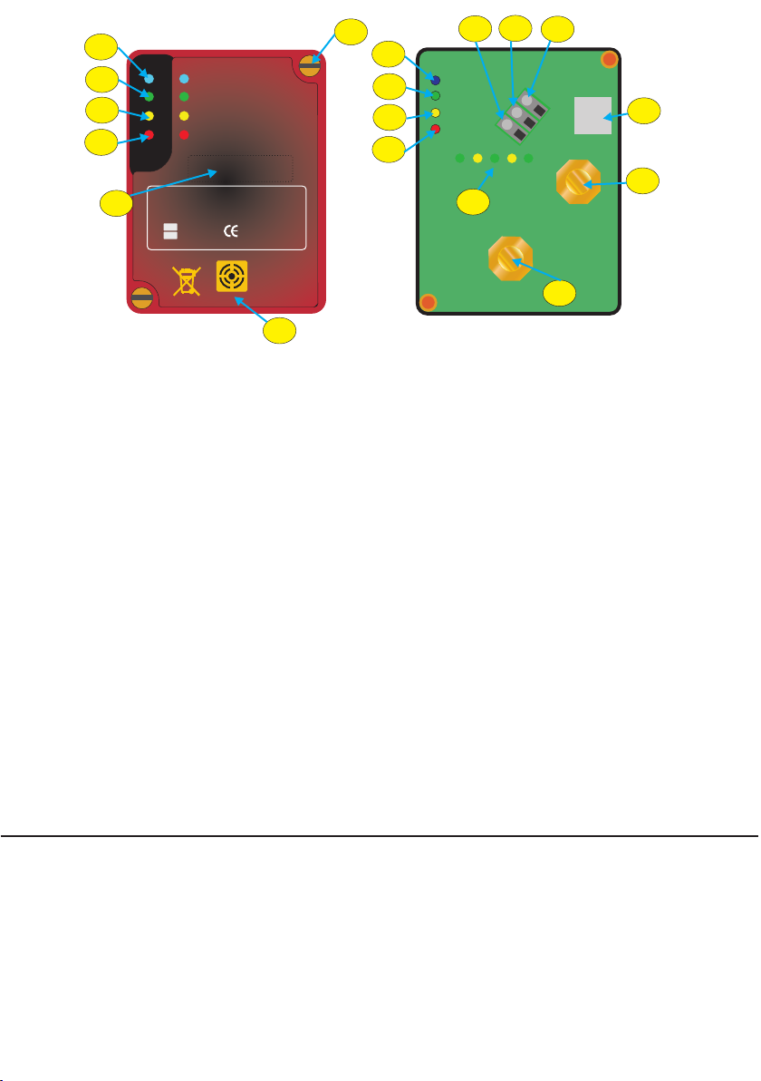
Product Information: Sleep Mode
1:Fault LED (predominant fault = highvoltage) In order to conserve power and keep quiescent current to a minimum only
2:Low voltage LED ‘on’if any terminal is below relay ‘off’voltage. the unit enters sleep mode. In sleep mode the main unit consumes 0.7mA
NOTE: Both the Fault (RED) and Low Voltage LEDs will come on and with the remote a total of 0.9mA for the remote + main unit combined.
simultaneously if any terminal is below 4V. The software will not allow the This relates to approximately 1Ah consumptionover 41days - very efficient!
The ProLatch R unit (Default)
relay to engage if either terminal is below 4V. As it assumes there is a major
Goes to sleep 0.1V below the OFF voltage setting - all the LEDs goes off
faultor reverse polarity on one ofthe battery banks.
after 20 seconds, the blue LED then flashes (highspeed speed) once every
3: Function select green LED, this LED is used on setup to pick the
60 seconds to suggest the device is still active. The background voltage
operation of choice for the product. Once set it will show which setting it is on
identification LEDs turn off below 13.3V in spite of how it’s set up) - the
everytime the product is activated .
numerical LCD display deactivates 120seconds after the LEDs turn off - this
4: Relay engaged LED; this shows that the relay circuit is in the closed or
isadjustable (see adjustments page)
contact position. Under default when below 13.3 volts (in engine protect /
The ProLatch R remote (Default)
starter protect) this will flash for a quick flash once every 60 secs to
All relevant LEDs will come on for 60 seconds - this is adjustable between 5
conserveas much electrical energy as possibleyet still portray information.
secondsand 600 seconds (see adjustments pageX ).
5: M4 screw securing lid to base, there are 2 screws diagonally opposite
When on ‘Charge mode’, the product goes to sleep when the voltage is 0.1
eachother which simply secures the lid.
voltsbelow the ‘on’voltage.
6: NEG. (battery negative connection) - connect to battery neg, this also is
For the ‘Battery protect’ and ‘Engine start protect’ it goes to sleep all the
used to link to configuration connection for setup purposes. Product only
time.
worksunder a common neg.
Onsleep mode lights will display for100 ms every minute.
7: CFG. (configuration connection see page5, fig4) - when connected to the
negativeit activates the magnetic control circuits.
66mAareconsumed when LEDs on remote andmain unit illuminate.
8: STD. Starter Motor Detection connector, this connects to the starter
motor activation solenoid ‘live’ signal from the ignition switch ( key ). This is
the signal which engages the starter motor to start the engine, this is the
signal which is also used to disengages the relay to protect the relay during
engine start up. This is used only when the relay is used for bidirectional
chargemode & not required on othermodes.
9: Remote control connector, simply attach the optional remote control to
thisconnector. Use silicon grease towaterproof the connector.
10: Input power connection, main D/C input cable, M6/M8 nut (dependent
ofwhich model purchased).
11:Outputconnection, main (suitably fused) output D/Ccable.
12:12V(green)/24V(yellow) select LED plus Sterling illumination.
13:Internally sealed magnet used to adjustsettings. Use as per page5, fig3.
14:Sterling logo (changes colour green 12V& yellow 24V)
IP68
waterproof
T
SD
F
CG
NEG
Installation - please allow a 2 inch (5cm) clearance around the entire unit when then the fuse, then connect them to the battery.This method is much safer than
fasteningtheunitto the mounting place. connecting cables to the batteries then connecting to the unit.
The actual installationof this deviceis very straightforward. Always bear in mind that even with 12 or 24 V if you are wet enough you can get
Please use the right cable for your device. The continuous current ratings are anelectrical shock and it could kill you, so, treat with care and ensure you are as
on the lid of the device.Also, please fuse all cables which go directly to a battery, dry as possible.
about 30% larger fuse than that of the product rating. It is recommended to place fuses as close to the batteries as possible,
also fit them first as they can protect against any accidents during installation.
Before starting this installation, disconnect the negative and positive cables The fuses are there to protect the cables in the event of the positive cable
from the batteries and ensure the circuit is isolated. This is to prevent any short coming into contact with the chassis of a vehicle, a steel hull (on a narrow boat)
circuits when running the new cables, a short circuit on a battery can easily or a bonding system on a boat or vehicle. In some case this is a statutory
cause a fire, or the battery in question could explode. - If in doubt please requirement. All wires going directly onto a battery should be fused. A rough
employa professional electrician to install theunit. Or,contact Sterling Power at guide for a fuse required for the D/C power cables is about 30-50% larger amp
help@sterling-power.com or see our web site www.sterling-power.com. If you rating than the products rated ability. I.e. a product which takes about 100 amps
areinAmericapleaseusewww.sterling-power-usa.com. would need about a 130-150 amp fuse. The relays have a 600% instant surge
Always work from the unit to the battery bank. I.e. fit the cables onto the unit, overload ability but this is only for milliseconds.
If there are any doubts or
problemspleasehavea professional install this unit.
Fuses.
Fig 1 Fig 2
WHAT CABLE TO USE / mm sq
0-25amps 6 mm sq 10mm sq
25-45amps 16 mm sq 25mm sq
45-85amps 25 mm sq 35 mm sq
85-125amps 35 mm sq 50mm sq
125- 180 amps 50mm sq 70 mmsq
180-330 amps 70mm sq 90 mm sq
Please note that if there is a problem obtaining, for example, 90 mm sq cable, simply
use 2 x 50 mm sq , or 3 x 35 mm sq , the cable is simply copper, , so simply double it up
this doesnot matter ifit is onecable or 10cables as longas the squarearea adds up.
Performanceof any productcan be improvedby thicker cable,so if indoubt round up.
Currentrequired Cable run 0-1.5m 1.5 – 4 m

A5amp fusewouldbesuffice .
Fuses are not supplied with the unit but can be purchased separate from your
local chandlery or from Sterling Power Products.
To install the unit, pick a cool part of the engine room ( i.e. as low down as possible
) . It also does not matter which way up the unit goes. However, the unit has been
designed so the cables do not run across the bolts from other battery banks. If the
unit is connected, as per the obvious writing on the unit, the cables should be
brought up from below. You can connect the unit at any angle you wish to assist in
the wiring process. Using the 4 fixing holes you can firmly secure it to a bulkhead.
When all cables are connected, tie and secure the cables in such a way as their
weight is supported on the bulkhead and they do not vibrate nor touch any of the
otherstuds.
Ensure your alternator/s or other charging sources are working within the total
limits of the unit. I.e. if the unit is 80 amps the total maximum current is 80 amps, it
is important to keep the alternator rating lower than the relay’s ability for optimal
andsafestoperation.
Ensure all cable connections are correctly crimped with the correct tools, and the
rubberbootssuppliedare used to cover the exposed connection on completion.
Fit in a position to minimize the length of cables used, the shorter the cables the
better. Look at the cable chart below for recommended cable sizes. Larger cables
are usually hard to come by; if, for example, you want a 200 amp cable, but only
have a 50 amp cable then simply run 4 lengths of 50 amp cable as, all you are
doing,isrunningcopper. for these models there is an LCD display
showing input voltage, output voltage (selectable), high voltage trip alarm,
The Pro Latch R can be configured into 4 different modes. Each of these background light ‘on / off’ , sleep mode inductor and 1 min emergency override
modes have a default setting. abilityandmanyother features.
A conventional split charge relay suffers from high
power consumption to run itself. If used solely for charging a system with an
alternator the power used by the relay is insignificant and, as such, irrelevant
compared to the power generated. However, if after the engine is switched ‘off’
and there are solar cells or wind charging systems in the boat/vehicle then the
ability to charge other battery banks becomes very important. Therefore, the
power consumption of the splitting device becomes extremely important and so
the latching relay comes into a world of its own. There is no limit to how many
battery banks that can be charged. On boats there could be as many as 2-5
battery banks, simply use the appropriate number of latching relays to charge all
the battery banks either from a high power or low power charging source. An
instant starter disengage circuit is built in. This prevents the starter motor’s high
current surge damaging the product, this open circuits the relay between
activatingthestartermotor and the bendix engaging the fly wheel.
The battery protect system, protects a battery bank
from premature and expensive destruction due to deep discharge or over
charging. It only takes one accidental deep discharge of a battery bank to destroy
that battery bank, a very expensive mistake indeed. This is most common on
things such as hire boats or hire equipment, such as electric cherry pickers,
where the hirer tends not to treat the equipment with the respect it deserves. This
leaves the owner with a large battery replacement bill. The battery protection
relay disconnects the batteries at a preset limit in order to protect the battery
bank. The unit has a built in warning system, i.e. it will switch the power ‘off’for 10
secs then back ‘on’ for 1 min to give a reasonable warning to allow the operator
time to complete the process, such as: start the engine or activate a battery
charger to take place to help the situation ( i.e. recharge the batteries ). This could
happen on a boat late at night, so, the extra minute allows some one to start the
engine to recover the batteries. For extra safety, the optional remote control gives
theoptiontooverride the trip for 1 min in the case of emergency.
forsignalwires (non current wires)
In a situation where you have a sealed lead acid (gel, AGM) starter battery and
an open lead acid domestic battery and you were fast charging your
domestic batteries at 14.8V using a shore powered battery charger / combined
inverter charger, you wouldn’t want to charge your AGM/Gel starter battery at
14.8V at the risk of damaging them.
The ProLatch R can therefore be implemented to isolate the starter and the
domestic when the domestic is being charged. In most situations the user will
be coming into shore and the relay will be engaged (allowing the domestic to
be charged from the engine starter). After arriving at shore and turning off the
engine the user must wait until the relay disengages (blue light turns off). Once
the relay is disengaged the user can then proceed to charge the domestic with
the shore powered battery charger and the relay shall remain disengaged.
IN THIS EXAMPLE unidirectional mode must be set at the starter battery side.
For example ‘ON’ voltage could be set at 13.3V - relay engaged domestic
being charged from starter. ‘OFF’ voltage could be set to 12.9V - when the
surface voltage of starter drops below 12.9V relay disengages. The relay will
then not engage again until the starter battery is being charged (surface
voltage raises above 13.3V).
required to fine tune the product to its application. It’s advisable to test this function
priortoreleasingthe job.
much the same features as the Bidirectional setting,
Sterling Power Products has a however, the relay will only be activated by a voltage in excess of 13.3V ( x 2 for 24
full range of high current fuses from 100-500 amps, the part number is GANLR for v ) on the input cable stud only, the output cable voltage will not activate the
the fuse holder and GANL100 for a 100 amp fuse and GANL200 for a 200 amp product. In the event that you need the output cable to do the activation simply
fuseetc. reversethecables.
It is advisable, when doing any work on boats, to have someone close to you in
case of any problems. It is also a good idea to have a bottle of fresh water near by
incase of an unlikely explosion occurring in one of the batteries, the water can be
usedtowashanyacid out of your eyes.
This mode is designed to allow products to be
safely run from an engine starter battery and disconnects the product at such a
stage as to allow the engine starter battery to retain enough power to ensure the
engine will start. Ideal applications for this product are things such as tail lifts on
lorries, mobility vehicles, over night lorries (with D/C equipment) or small
inverters used on vans etc., where the addition of a split charge system and an
extra battery bank may not be warranted nor feasible ( obviously there are many
more applications for these products ). The product will then be automatically re-
engaged when the engine is started and/or the battery charged. Depending on
battery type this is the most likely mode where voltage adjustment maybe
4) Unidirectional charging:
Optional remote control features:
1) Bidirectional charging:
2) Battery Protection Mode:
3) Engine Start Protection Mode:
Examples of unidirectional charging
the unit is set as a charging
relay as new out of the box. If this is the function that you require then simply install
theunit.
The unit will power-up resulting in the illumination of all four indication LEDs and
then illuminate only the GREEN and YELLOW LED ( if voltage under 13.3 volts x 2
for 24 v ) or green and blue if over 13.3 volts ( relay engaged ) . The green should
besolid(non flashing ) this confirms the unit is on ‘Bi directional charging mode’.
If you wish to change the mode to battery protect, start protect or uni directional
followtheprocedurebelow:
1. Remove the negative wire from battery terminal.
2.Removethelid by unscrewing the 2 screws securing the lid.
3. Using a small 1 or 2 inch (2.5-5cm) cable, link from CFG (7) to NEG (6) this will
result in two wires being in the NEG terminal (The link wire and the original
negative).
4. Remove the positive wire from your battery or target which connects to the ‘out’
terminal of the relay. Make sure there is absolutely no voltage on the output
terminal.
5.Now reconnect the negative wire back to your battery or distribution block (as
point1).The unit should start up in configuration mode.
6.The unit will display all four information LED lights for 3 seconds ( blue , green.
yellowandred)to test the LEDs are ok.
7.The unit will auto select 12V or 24V operation based on the input voltage ( its
there for important to ensure the battery bank is not totally flat. , the row of 6
LEDs behind the Sterling logo will illuminate, there are 4 green and 2 yellow.
Note: GREEN = 12V installation, yellow = 24V installation. The correct LED
indicators will then remain illuminated e.g. green =12V / yellow = 24V.
8.Once the blue and yellow LED lights switch off the unit is in programming
mode ( green and red leds on ) .
How to select between the 4 modes
Factory default setting and brief installation guide:
Refertofigs1+2(page2)and figs3-10 (page5+6).Assumingunitis correctly wired.
For safety reasons remove the wires from the batteries rather than the unit; this
preventsloose,live wires floating around the product area.
How to adjust the main settings :

NOTE: The RED LED indicates programming mode, the GREEN LED denotes N.B: Power MUST be applied after the 'CFG' terminal is connected to the
theprogramselected, as below: 'Ground' terminal.
N.B:GREEN=12Vinstallation,YELLOW = 24V installation.
SolidGREENLED:Bidirectionalcharging mode ( factory default mode ) 4. The unit will display all four information LED lights for 3 seconds then flashes
greenandyellowtostart the sequence starting with the on voltage first.
'ON' Voltage Configuration: Yellow and green LED
It is important to be ready and count the number of green flashes that occur, the
SingleFlashGREENLED: Battery Protect mode
green flashes will repeat themselves one more time after about 10 seconds in
case you missed the first count. Please note the number, when you have the
DoubleFlashGREENLED:StarterProtect Function
number of green flashes then simply relate the number to the table on page 5.
The number will show you the current voltage settings, if you want to change this
voltage then add the number of “swipes “ you will need to make to move the
9. The high voltage trip LED (red) should be on and the selected function LED will
voltage from the current voltage to the new voltage. I.e. if I have 33 flashes this is
be on as well. It is now in bidirectional charging mode. If you want to keep it in
13.3V. However, if I require 13.8V,I will need to add 5 swipes to achieve the new
bidirectional charging mode carefully remove the wire from the CFG terminal.
voltageandanewcount of 38 flashes.
This will lock this mode into the software (be careful not to touch the input terminal
7. To change the set 'ON' voltage, briefly place the magnet (integrated into the
withthewire).
lid) above the BLUE LED on the unit as per page 5 fig 3 ( magnetic swipe area) at
10. To change function you need to hold the lid (which contains the magnet) and
anytimeduringthe flashing sequence.
place the ‘magnetic swipe’ area (highlighted on the lid) over the side of the unit
8. When the magnet is detected the BLUE LED is illuminated and the selected
beside the blue LED (refer to page 5 , diagram fig.3 for magnetic area) until the
voltage is increased by 0.1V (which is one green flash). This can be done
blue light comes on. When the blue light comes on withdraw the lid- the blue light
multipletimesto achieve your required voltage. Keep note of your count.
should go off (this indicates you have progressed 1 step in the program
9. Each time the voltage is increased the YELLOW LED light restarts its count to
selection). You have now changed the mode to ‘Uni Directional mode and you
52flashes.(thisis the reference only and not the voltage setting )
should see the green light flash 3 times ) . If you do not want this mode then
NOTE: To set a voltage which is lower than the current voltage you need to count
repositionthemagnetagain etc
up only when you reach 15V then simply roll over onto the bottom of the table and
11. When you have selected the node you want simply remove the config wire link
add up again. I.e. you could have to swipe up to 50 times to achieve a lower
addthisillbe locked into the processor.
voltage.
12. Now wait until the red LED turns off and the saved function shall be display via
10. When the YELLOW LED light is allowed to flash 52 times the 'ON' voltage is
the green function LED for another 10 seconds ( ie green led flashing or not to
configured,andtheunit will automatically change to 'OFF' voltage configuration.
showselectedfunction) .Afterthat,theunitwill restart.
The unit will then automatically roll on to off voltage configuration, shown by the
13. The NEG to CFG link should now have been removed. leaving only the
greenandyellowLEDchanging to red and yellow LED.
system Neg in place. For safety purposes we recommend to first disconnect the
'OFF' Voltage Configuration: Yellow and red LED
negative from your battery or distribution block to avoid any arching / shorting of
11. The off voltage is now automatically preset to a minimum of 0.3V (charging
thesystem.
mode) below the adjusted ON voltage. E.g. If you now have set the ON voltage
to 14.1V the OFF voltage will be 13.8V. You proceed with value (13.8V) and
every change will now decrease by 0.1V units rather than increase as in ON
configuration.After the first 52 flash cycle the YELLOW LED will flash another 52
timestoconfirmyour ON voltage setting.
Bi/Uni-directional chargingFunction: 12. The YELLOW LED light will start to flash 52 times (for reference purposes
only) with the RED LED light flashing according to the voltage configured (see
needsatleast4 v on output to close otherwise assume fault voltageflashingtablebelow).
Battery Protect Function: If the voltage is above 13.3V the relay will engage 13. To change the set 'OFF' voltage, briefly place the magnet (integrated into the
immediatelywithoutadelay. lid)abovetheBLUELEDontheunit.
14. When the magnet is detected the BLUE LED is illuminated and the selected
voltage is decreased by 0.1V (which is one green flash). This can be done
Engine Battery Protect Function: multipletimesto achieve your require voltage
15. Each time the voltage is decreased the YELLOW LED light restarts its count
willclosewithno voltage as no battery connected. to 52 flashes.
Availablevoltage range NOTE: when the voltage reaches the lower limit (10.0V) it will roll over to the ON
voltageminus0.3V.
NOTE: The unit intelligently monitors the input voltage of the unit; if the input 16. When the YELLOW LED light is allowed to flash 52 times the 'OFF' voltage is
voltage rises slowly through the ON threshold the unit will delay the relay connect configured.
for a period of time to allow the input battery to regain charge before the 17. Wait until the BLUE and GREEN LEDs flash, only when these LEDs are
secondary battery is connected to the system. The above voltages are not instant flashingtheconfiguration has been saved.
theyhavealgorithmsattached relating to the trend of the voltages. 18. Switch offpower to the unit.
In the event that the above preset voltages are not to your application and 19. Disconnect the loop wires from the 'CFG' terminal.
requires “tweaking” ( most likely in engine start protection mode ) then they can be
adjusted. This is extremely unlikely thing to have to do and the instructions should
bereadandunderstoodbefore attempting the process.
In the event of any voltages requiring adjustments please note that the 'ON'
voltage MUST be ≥0.3V above 'OFF' voltage for unit to function correctly.
To adjust 'ON'/'OFF' Voltage Configuration: “tweak”(assuming already correctly
wired)
1.Connect a thin loop of wire between the 'CFG' and 'NEG' terminals of the unit. (
toactivatetheswipe control )
2.Disconnectanycables from the battery 'IN' terminal.
3.Connectaminimumof 10V (10-30V) to 'OUT' terminal ONLY.
Turn ON 13.3V (either terminal) OFF 12.9V (either terminal)
Turn ON 13.3V (one terminal) OFF 12.9V (one terminal)
TurnON 12.8V OFF 10.9V
TurnON 12.9V OFF 12.3V
Turn ON 13.3V Turn OFF 12.9V
Turn ON 12.8V Turn OFF 10.9V
Turn ON 12.9V Turn OFF 12.3V
ON 10.3 -15.0V
OFF 10.0 - 14.7V
TripleFlash GREEN LED: Unidirectional charging mode
The DEFAULT ,ON/OFF voltage are as below - these voltages are not absolute
- they are algorithm based i.e. there is a time / voltage differential algorithm (trend)
inplaytoensure best performance.
(x2for24v settings )
High V
trip15.5Vx2(31V) for 24V systems.
All adjustments/setup values are based on 12V only. I.e. any 24V
requirements require the desired values to be divided by 2 to make 12V. I.e.
if you want 28.4V on a setting set for 14.1V, then, when the unit fires up it will
select 12 or 24V mode of operation the desired voltages will then be
achieved by the automatic operation.
Magnetic field warning:
There is a small magnet fitted in the lid of this
product under the label marked ‘magnetic area’.
With the vast majority of installations this will
have no effect on anything, however this magnet
may influence a magnetic susceptible product
such as a magnetic compass. Please check your
magnetic sensitive products after installation of
this device. If there is an adverse affect then you
can peel back the lower section of the label on
the lid of the product and remove the magnet.

+
+
+
IN
OUT
Engine
Starter
motor
primary/starter battery
Alternator
Starter motor
solenoid
secondary/ Domestic battery
Battery Charger
Combi inverter
Solar
Wind
D
ST
CFG
NEG
REMOTE
IGNITION KEY
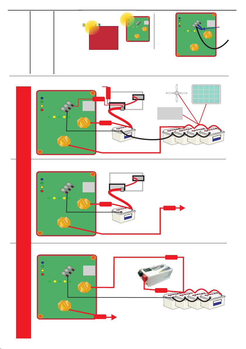
STARTER
Suggested wiring for:
Bidirectional Charging
+
+
+
IN
OUT
Engine
Starter
motor
primary/starter battery
Alternator
Starter motor
solenoid
STD
F
CG
NEG
REMOTE
Suggested Wiring for:
Engine starter protect
Connect to
Product/system
running from engine
starter battery ie
Inverter
Fridge
TV
Emergency lights
Tail Lift
Power tools
Charging systems
Etc Etc
+
+
+
IN
OUT
secondary/ Domestic battery
D
ST
CFG
NEG
REMOTE
Suggested wiring for:
Battery Protection relay
Connect to
Product/system
running from engine
starter battery ie
Small Inverter, Fridge
TV, Emergency lights
Tail Lift, Power tools
Charging systems,
Lights etc etc
All wires connected directly to a battery should be fused in accordance the the current flow
All wires connected directly to a battery should be fused in accordance the the current flow
All wires connected directly to a battery should be fused in accordance to the current flow
Large inverters and other
equipment may already
have low voltage trips
built into their circuits.
So, no need to feed them
through the
Battery Protect system
to
negative
Side profile
Magnetic swipe area
the magnetic reed switch
is behind the plastic case in
this area
+
+
+
IN
OUT
STD
GCF
NEG
REMOTE
+
+
+
IN
OUT
STD
CFG
NG
E
REMOTE
Add small
link wire to
access
config program,
remove
after config.
To adjust
preset
voltage
settings
you must
access the
config
setting
Fig 3 Fig 4
Fig 5
Fig 6
Fig 7
Flashes Volts Flashes Volts Flashes Volts
0
1
2
3
4
5
6
7
8
9
10
11
12
13
14
15
16
10.0
10.1
10.2
10.3
10.4
10.5
10.6
10.7
10.8
10.9
11.0
11.1
11.2
11.3
11.4
11.5
11.6
17
18
19
20
21
22
23
24
25
26
27
28
29
30
31
32
33
11.7
11.8
11.9
12.0
12.1
12.2
12.3
12.4
12.5
12.6
12.7
12.8
12.9
13.0
13.1
13.2
13.3
Voltage Configuration Table
for Green (ON) & Red (OFF) flashing LEDs
for 24 v divide by 2
34
35
36
37
38
39
40
41
42
43
44
45
46
47
48
49
50
13.4
13.5
13.6
13.7
13.8
13.9
14.0
14.1
14.2
14.3
14.4
14.5
14.6
14.7
14.8
14.9
15.0
Fuse
Fuse
Fuse
Fuse
Fuse
Fuse
Fuse
Fuse
Fuses: All cables going to a battery bank must be fuses as close to the battery as possible, the recommendation is within 170 mm or 7 inches
off the battery. Signal wire fuses should be about 3 amps, main fuses should be about 30% higher than the rating of the product, ie if the relay
is 80 amps then about a 100 amp fuse would be suitable.
Table 1

+
+
+
IN
OUT
Engine
Starter
motor
Alternator
Starter motor
solenoid
STD
CFG
NEG
REMOTE
Product protect mode. You may wish to protect expensive equipment such as a RADAR,
fish finders, etc. from high voltage, they can easily be isolated onto a separate circuit
Suggested wiring for Battery Protection relay being used as a product protect device
+
+
+
IN
OUT
secondary/ Domestic battery
S D
T
F
C G
NEG
REMOTE
All wires connected directly to a battery should be fused in accordance the the current flow
To lights etc on boat
To radar/ fish finders
expensive equipment requiring
over voltage protection
Unit on Battery protect mode has 15.3 over voltage trip
In the event of using a latching relay as a
then if the unit is used for a engine start battery,
USA regulations and CE regulations
require an emergency bypass to be available
in the event of the relay becoming defective.
A manual override must be present,
simply add an isolation switch between the input
and output terminals to bypass the product in emergency
Remote battery isolator / protect.
+
+
+
IN
OUT
Engine
Starter
motor
primary/starter battery
Alternator
Starter motor
solenoid
secondary/ Domestic battery
Solar
Wind
STD
FG
C
E
NG
REMOTE
IGNITION KEY
STARTER
VSR
Charging relay
Mode
Multi use system , on boat with bow thruster/ anchor winch, and gen set, all battery banks
being charged with all sources . Used for charging and battery protect modes
Anchor winch/ bow thruster Generator
starter battery
+
+
+
IN
OUT
STD
CFG
NEG
REMOTE
To Bow
Thruster
+
+
+
IN
OUT
STD
CFG
NEG
REMOTE
+
+
+
IN
OUT
STD
FG
C
NEG
REMOTE
To Boats
Electrics
VSR
Charging relay
Mode
VSR
Charging relay
Mode
Battery Protect
Mode
6 mm
dia
Emergency
by pass switch
/ override
Sterling Power Products
Back light
Alarm
V12.6
Sleep Alarm
Closed
In
Select
Over ride
To over ride
hold for 5 sec
Audible alarm
disconnect
hold 5 sec
Latching
relay
Out
Fig 8
Fig 9
Fig 10
Fuse
Fuse
Fuse
Fuse
Fuse
Fuse
Fuse
Fuse
Fuse
Fuse
Fuse
Fuse
Fuse
Fuse Fuse
Fuse
Fuse
Fuse

Additional Information
High voltage trip
Low voltage trip (charging mode only)
More than 15.9V on either terminal = RED LED ON-> relay open.
Less than 14.0V on both terminal = RED LED OFF -> voltage trip reset
If voltage is below the set ‘off’ voltage = YELLOW LED ON until sleep
mode.
Less than 4.0V on either terminal = YELLOW LED ON -> relay stays
open.
Relay algorithmic time delay
Thealgorithm time delay works to reducerelay wear/tear and chattering :
For an example in charging mode: (e.g: on voltage = 13.3V, off voltage =
12.9V).
close circuit:
If voltage 13.3V it takes 3 min.
If voltage 13.4V it takes 90 sec.
If voltage 13.5V it takes 45 sec.
If voltage 13.6V it takes 22 sec.
If voltage 13.7V it takes 11 sec.
If voltage > 13.7V it takes 5 sec.
open circuit:
if voltage 12.9V it takes 3 min.
if voltage 12.8V it takes 90 sec.
if voltage 12.7V it takes 45 sec.
if voltage < 12.7V it takes 22 sec.
if voltage < 10.5V open immediately
Optional remote control:
Principle Features
* 10m extension cable
* Allows user to view in / output voltages remotely
* Allows the user to see which of the 4 modes are running
* Has a colour coded background LED screen - i.e red for danger,
green for OK and blue for charging.
* Allows the user to adjust low/high voltage alarm settings, sleep
settings and emergency settings etc.
Sterling power products:
www.sterling-power.com www.sterling-power-usa.com help@sterling-power.com
This product carries a 2 year return to factory warranty,
we cannot he held responsible for carriage charges to or
from the factory or the cost of any work incurred in replacing the item.
Where as legally all warrantees should go through the persons supplying
you the product, however, Sterling recognises that due to the international
nature of this business and the time added to repairs that this is not
always the best solution, as such we are happy to help direct from
the factory if possible, please understand that this help is at our
discretion and not a legal requirement.
English
French
Deutsch
Sterling Power Products
Back
light
V12.6
Sleep Alarm
Closed
In
Select
Out
Latching relay

English
French
Deutsch
Pro
Latch R
Stellen Sie sicher dass der Leistungswert des Relais größer ist als der
maximale Stromwert der vom Stromerzeuger (zB Lichtmaschine)
hergestellt werden kann um Schaden am Gerät zu vermeiden.
Die Größe der Batteriebank ist nicht relevant.
www.sterling-power.com
www.sterling-power-usa.com
12/24 V Automatische Auswahl
Modelle (Amp) 80 160
Relais konstante Leistung (Amp) 80 160 240
Sofortige Überladung (Amp) 500 1000 1500
Stromverbrauch
240
:
S
Hochspannung Auslöser 15.5 V bei 12 V - 31 V bei 24 V
leepmodus ( quiescent current ) 1 mA
Aktiv unter Leistung 20 mA
Sleep + Fernbedienung Sleep 3mA
Gerät + Fernbedienung unter Leistung 40mA
Gerät + Fernbedienung + Hintergrundlicht LCD 60mA
Dieses Gerät hat den
aktuellsten aktiven
progressiven
Abtrennungsalgorithmus
installiert um unnötige
Verbindungen und
Abtrennungen des Relais
zu vermeiden. Daher gibt
es einige
Zeitverzögerungen zw
den Werten die der Kunde
als Abstellpunkt
eingegeben hat und dem
Punkt an dem das Gerät
tatsächlich abschaltet.
Die Verzögerung wird
reduziert je niedriger die
Spannung (unter der
programmierten
Abstellspannung).
Designed und entwickelt in England
Wählbares
2) Starterbatterie-Entladungsschutz-Funktion
3) Startbatterie-Tiefentladungsschutz-Funktion
4) Unidirektionales Relais
Latching Relais: 80/160/240 Amp Modelle
Magnetisch programmierbar für folgende Funktionen:
1) Bi-stabiles Relais
Sterling Power Products
Sterling
www.sterling-power.com www.sterling-power-usa.com
RoHS
compliant
Magnetic swipe
Green 12 volt : Yellow 24 volt
Extra help labels
under lid &
under box
Relay engaged
Function selected
Low input voltage
High voltage trip
Solid charging relay mode
Flash battery protect mode
2 Flash engine start protect
Designed and manufactured in England
Selectable, Latching Relay:
Programmable for: Charging Relay,
Engine Start or Battery & Product Protect
Continuous rating: ----- instantaneous:
80 amp 500 amps
160 amp 1000 amps
240 amp 1500 amps
IP 68
Waterproof
Sterling Power Products
Back
light
V12.6
Sleep Alarm
Closed
In
Select
Out
Display der optionalen
Fernbedienung wechselt Farbe
abhängig vom Zustand
des Relais
Garantie:
2 Jahre Garantie am
Werk
RoHS
compliant
Sterling
www.sterling-power.com www.sterling-power-usa.com
RoHS
compliant
Magnetic swipe
Selectable, Latching Relay:
Programmable for: Charging Relay,
Engine Start or Battery Product Protect
Continuos rating: ----- Intermittent:
80 amp 200 amps
160 amp 400 amps
Automatic 12/24 v select
Green 12 volt : Yellow 24 volt
Extra help labels
under lid &
under box
Relay engaged
Function selected
Low input voltage
Fault / High Voltage trip
Solid green = bidirectional charge
Flash green = battery protect
2 Flash green = engine start protect
3 Flash green = unidirectional charge
Designed and manufactured in England
IP68
waterproof
Latching relay

+
+
+
IN
OUT
Sterling
www.sterling-power.com www.sterling-power-usa.com
RoHS
compliant
Magnetic swipe
Selectable, Latching Relay:
Programmable for: Charging Relay,
Engine Start or Battery Product Protect
Continuos rating: ----- Intermittent:
80 amp 200 amps
160 amp 400 amps
Automatic 12/24 v select
Green 12 volt : Yellow 24 volt
Extra help labels
under lid &
under box
Relay engaged
Function selected
Low input voltage
Fault / High Voltage trip
Solid green = bidirectional charge
Flash green = battery protect
2 Flash green = engine start protect
3 Flash green = unidirectional charge
Designed and manufactured in England
1
2
3
45
1
2
3
4
6
78
9
10
11
12
13
14
Produkt Information: 13: Interner abgedichteter Magnet zum Einstellen von Optionen. Gebrauch
1:Fehlert LED (häufigster Fehler = zuhohe Spannung) laut Seite 12, fig3.
2: Niedrigspannung LED ‘an’ falls ein Terminal unterhalb der ‘off’ Spannung
liegt. Schlafmodus
ACHTUNG: Sowohl das Fehler(ROT) und Niedrigspannung-LEDs leuchten Um Strom zu sparen und den Ruhestrom niedrig zu halten geht das Gerät in
auf falls ein Terminal unterhalb von 4V liegt. Die Software wird in dem Fall Schlafmodus. Im Schlafmodus braucht das Hauptgerät 0.7mA und mit der
kein Einschalten ermöglichen, da angenommen wird dass ein schwerer Fernbedienung gemeinsam 0.9mA. Das macht einen Verbrauch von etwa
Fehleroder umgekehrte Polarität an einer derBatteriebänke vorliegt. 1Ah Verbrauch über 41 Tage -sehr effizient!
Das ProLatch R Gerät (Standard)
3: “Function selected” grünes LED, dieses LED brauchen Sie um den
geht in den Schlafmodus bei 0.1V unterhalb der OFF Spannung - alle LEDs
gewünschten Operationsmodus auszuwählen. Nach Aktivierung wird dies
gehen nach 20 Sek aus, das blaue LED blinkt einmal alle 60 Sek um
beijedem Neustart angezeigt.
anzuzeigen dass es noch immer aktiv ist. Die Hintergrund LEDs zur
4: “Relay engaged” LED; zeigt dass der Relais-Kreislauf geschlossen ist
Spannungserkennung stellen sich bei unter 13,3V ab, egal was eingestellt
oder in Kontakt-Position ist. Unter der Standardeinstellung bei weniger als
wurde -das numerische LCD Display deaktiviert sich 120 Sekunden
13.3V(Motor-Schutz/Starter-Schutz)leuchtet dies alle 60 Sek kurzauf.
nachdemdie LEDs sich abschalten - dieskann abgeaendert werden.
5: M4 Schraube welche den Deckel sichert, davon gibt es 2 die diagonal
Die ProLatch R Fernbedienung (Standard)
gegenüberliegen
Alle relevanten LEDs kommen für 60 Sek an - kann zw 5 und 600 Sek
6: NEG. (Batterie negativ Verbindung) - Anschluss zum neg Batteriepol,
eingestelltwerden.
auch als Link zur Konfiguration desAnschlusses für Setup Zwecke. Produkt
Wenn im Lademodus geht das Ladegerät in den Schlafmodus bei einer
funktioniertnur unter einem gemeinsamen Negativ.
Spannungvon 0,1V unter der “an” Spannung.
7: CFG. (Konfigurationsanschluss siehe Seite 12, fig4) - wenn mit negativ
Bei ‘Batterieschutz’ und ‘Motorstartschutz’ geht es dauernd in den
verbunden,dies aktiviert die magnetischen Kontrollkreisläufe.
Schlafmodus.
8: STD. Starter-Motor-Finder, verbindet mit dem elektromagnetischen
ImSchlafmodus werden die Lichter fuer 100msjede Minute aufleuchten.
Signal der Zündung des Starter-Motors. Dieses Signal zeigt dem
Wenn LEDs an Fernbedienung und Hauptgerät aufleuchten werden 66mA
Startermotor an den Motor zu starten. Es schaltet ausserdem auch das
verbraucht.
Relais während des Motorstartes ab, um das Relais zu schützen. Dies wird
verwendet wenn das Relais im bidirektionalen Modus verwendet wird, in
jedemanderen Modus wird dies nicht benötigt.
9: Verbindung für Fernbedienung, stecken Sie hier die optionale
fernbedienung an. Verwenden Sie Silikonschmiere um die Verbindung
wasserfestzu machen.
10: Input Stromverbindung, Haupt- D/C Eingangskabel, M6/M8 Nuß (von
Modelabhängig).
11: Output Verbindung, Haupt- (ausreichend gesichert) Ausgangs- D/C
Kabel.
12:12V(grün)/24V(gelb)Auswahl LED mit Sterling Illumination.
14:Sterling Logo (ändert Farbe grün 12V& gelb 24V)
IP68
waterproof
T
SD
F
CG
NEG
Installation - bitte 5cm Platz rund um das gesamte Gerät lassen wenn es Kabel an das gerät an, dann die Sicherungen, dann zur Batterie. Diese
eingebautwird.DieInstallation dieses Gerätes ist sehr einfach. Methode ist sehr viel Sicherer als in die umgekehrte Richtung.
Bitte verwenden Sie das passende Kabel für Ihr Gerät. Der Dauerstrom ist am Nehmen Sie in Bedacht dass selbst 12V oder 24V tödlich sein können falls Sie
Deckel des Gerätes angegeben. Bitte installieren Sie Sicherungen an alle nass sind und sich einen elektrischen Schock holen. Beim arbeiten mit Strom!
Kabel die direkt zur Batterie gehen, die Sicherung soll etwa 30% größer sein als
die Leistung des Gerätes. . sollten immer so nahe als möglich zu den Batterien gesetzt
werden. Installieren Sie diese zuerst, da sie vor eventuellen Unfällen während
BevorSie den Einbau beginnen, nehmen Sie die negativen und positiven Kabel der Installation schützen können. Die Sicherungen schützen die Kabel für den
von der Batterie und stellen sicher dass der Kreislauf isoliert ist. Dies ist um Fall dass das positive Kabel mit dem Chassis eines Fahrzeuges oder dem
einen Kurzschluß zu vermeiden. Ein Kurzschluß an einer Batterie kann sehr Stahlrumpf eines Bootes in Berührung kommt. Dies kann gesetzlich
leicht ein Feuer verursachen oder die Batterie könnte explodieren. . -Bei vorgeschrieben sein. Alle Kabel die direkt zu einer batterie gehen sollten mit
Zweifel lassen Sie die Installation durch einen Profi durchführen, oder Sicherungen geschützt sein. Die Sicherung für Stromkabel sollte etwa 30-50%
kontaktieren Sie Sterling Power unter help@sterling-power.com oder gehen größer sein als die mögliche Leistung des Produktes. zB ein Gerät das 100Amp
Sie zu unserer Webseite www.sterling-power.com. In Amerika verwenden Sie nimmt braucht in etwa eine 130-150 Amp Sicherung. Die Relais haben einen
bitte usewww.sterling-power-usa.com. 600%Überspannungsschutzfunktion,dies hält jedoch bloß für Milisekunden.
Arbeiten Sie immer vom gerät zu den Batterien hin, d.h. schliessen Sie die
Falls Sie Zweifel oder Probleme haben, lassen Sie
diesesGerätbittedurch einen Profi einbauen.
solltenSieimmerso trocken als möglich sein!
Sicherungen.
Fig 1 Fig 2
WHAT CABLE TO USE / mm sq
0-25Amp 6 mm²10 mm²
25-45Amp 16 mm² 25 mm²
45-85Amp 25 mm²35 mm²
85-125Amp 35 mm²50 mm²
125- 180Amp 50mm²70 mm²
180-330Amp 70mm²90 mm²
Falls Sie kein passendes Kabel finden können, zum Beispiel 90 mm²Kabel, nehmen
Sieeinfach 2 x 50mm², oder 3 x35 mm²,
Die Leistung jedes Produktes kann mit höherer Kabelgrösse verbessert werden, im
Zweifelsfallealso einfach aufrunden.
Strom benötigt KabelLauf 0-1.5 m 1.5 – 4 m

Eine 5AmpSicherungistausreichendbeiSignalkabeln (ohne Stromfluss)
Sicherungen sind nicht beigelegt, können jedoch von Ihrem örtlichen
Yachtausrüster oder von Sterling Power Products erworben werden.
Zur Installation sollten Sie einen kühlen Teil des Motorraumes wühlen (so niedrig
als möglich). Es ist egal in welcher Position das Gerät installiert wird. Es wurde
jedoch so designt dass die Kabel dass die Kabel nicht über die Bolzen anderer
Batterien laufen. Wenn das Gerät angeschlossen ist, wie laut Beschriftung auf
dem Gerät ersichtlich, sollten die Kabel von unterhalb zugeführt werden. Das
Gerät kann in jedem Winkel angebracht werden um der Verkabelung zu helfen.
Durch die 4 Montagelöcher kann das Gerät fest an einer Schottwand angebracht
werden. Wenn alle Kabel verbunden sind, fixieren Sie diese so, dass deren
Gewicht von der Schottwand getragen wird und sie nicht vibrieren können oder
andereBolzenberühren.
Stellen Sie sicher dass Ihre Lichtmachine, oder andere Ladequellen innerhalb
der Gesamtleistug des Gerätes liegenzB wenn das Gerät 80Amp ist soll der max
Gesamtstrom 80Amp sein. Es ist wichtig dass der Lichtmaschinenwert unterhalb
demdesRelaisliegt um optimale Leistung und Sicherheit zu garantieren.
Stellen Sie sicher dass alle Kabelverbindungen ordentlich gecrimpt wurden und
dass das korrekte Werkzeug verwendet wurde. Die beiliegenden Gummischuhe
sollen verwendet werdne um die freiliegenden Verbindungen nach Abschluss
derInstallationabzudecken.
Die Länge der Kabel soll zu einem Minimum gehalten werden, je kürzer desto
besser. Checken Sie in der Liste unten für optimale Kabelgrösse. Grössere für
Kabel sind oft schwer zu finden; Falls Sie ein 200Amp Kabel benötigen, jedoch
bloß ein 50Amp Kabel zur verfügugn haben, dann legen Sie einfach 4 Längen
von50AmpKabel,dasie effektivbloß Kupfer verlegen. features.
Das Pro Latch R kann auf 4 unterschiedliche Modi eingestellt werden.
Jeder Modus hat eine Standardeinstellung.
Ein gewöhnliches Split-Laderelais braucht sehr viel
Strom um aktiv zu bleiben. Wenn es ausschließlich zum Laden eines Systems
mit einer Lichtmaschine gebaucht wird dann ist der Stromverbrauch nicht
signifikant im Vergleich zum erzeugten Strom. Wenn jedoch andere Solarzellen
oder Windladesysteme an Bord sind nachdem der Motor abgestellt wurde, dann
ist es wichtig die Mäglichkeit zu haben andere Batteriebänke zu laden. Daher
wird auch der Stromverbrauch des Split-Ladesystems sehr wichtig. Es gibt kein
Limit für die Anzahl der Batteriebänke die geladen werden können. Auf Booten
kann es bis zu 2-5 Bänke geben, verwenden Sie die passende Anzahl an
Latching Relais um alle Batteriebänke von einer Niedrig- oder Hochstromquelle
zu laden. Ein Kreislauf zum sofortigen Auslösen ist vorhanden. Dies verhindert
Beschädigung durch den hohen Startstrom des Startermotors und öffnet den
KreislaufbisdasBendix Laufwerk das Schwungrad aktiviert.
Der Batterieschutzmodus schützt eine Batteriebank vor
vorzeitiger und teurer Schädigung durch Tiefentladung oder Überladung. Eine
Batteriebank kann bereits durch eine, unbeabsichtigte Entladung zerstört
werden, das ist ein teurer Fehler. Die ist das häufigste Problem welches an
Mietbooten oder Miet-Equipment auftritt. Der Eigentümer muss dann die teure
Rechnung für die Ersatzbatterien bezahlen. Das Batterieschutzrelais trennt die
Batterien bei einem vorhandenen Limit um die Batteriebank zu schützen. Das
Gerät hat ein internes Warnsystem welches den Strom für 10 Sek abstellt, dann
wieder “an” für 1 Minute um angemessen Zeitraum zum Abschließen des
Vorganges zu geben, zB den Motor zu starten oder ein Ersatzladegerät
einzuschalten um der Situation zu helfen. ( zB. die Batterien wieder aufladen).
Dies könnte auf einem Boot spätnachts passieren und gibt eine extra Minute um
den Motor zu starten um die Batterien zu retten. Für extra Sicherheit gibt es eine
optionale Fernbedienung die die Option hat den Ausfall für eine Minute zu
verzögernimFalleeines Notfalles.
anzupassen. Es wird empfohlen diese Funktion vor der ersten Anwendung zu
testen.
hauptsächlich die selben Features als beim
Sterling Bidirektionalen laden, das Relais wird jedoch bloß bei einer Spannung von mehr
Power Products hat ein volles Sortiment von Hochstromsicherungen zw 100-500 als 13,3V(x2 bei 24V) am Eingangsbolzen aktiviert. Die Ausgangsspannung wird
Amp, die Produktnummer für den Sicherungshalter ist GANLR und GANL100 für das Produkt nicht aktivieren. Falls Sie die Aktivierung durch das Ausgangskabel
eine100AmpSicherung,GANL200füreine200AmpSicherung, usw. benötigen,drehen Sie die Kabel einfach um.
Es ist empfohlen jemanden in der Nähe zu haben wenn Sie am Boot arbeiten, für
den Fall dass Probleme auftreten. Sie sollten auch eine Flasche Wasser zur
Hand haben für den unwarscheinlichen fall dass eine Batterie explodiert. Mit dem
Wasserkann Säure aus denAugen gewaschen werden.
In diesem Modus können Geräte sicher von einer
Startermotorbatterie laufen und das Gerät schaltet rechtzeitig ab, sodass die
Startermotorbatterie genügend Strom bewahrt um den Motor zu starten. Die
ideale Anwendung wäre etwa bei Hubliften an LKWs, Behindertenfahrzeuge,
kleine Wechselrichter die an Vans laufen, etc.. bei denen ein zusätzliches
Trennladesystemund eine extra Batteriebank nicht plausibel sind. (natürlich gibt
es noch viele andere Anwendungen). Das Relais wird dann wieder automatisch
verbunden wenn der Motor gestartet oder die Batterie geladen wird. Abhängig
vom Batterietyp, dies ist der Modus in dem es am warscheinlichsten ist dass eine
Feineinstellung der Spannung benötigt wird um das produkt der Aufgabe
4) Unidirektionales Laden:
Optionale Fernbedienung:
1) Bidirektionales Laden:
2) Batterieschutzmodus:
3) Motorstart Schutzmodus:
Beispiele für unidirektionales Laden
Nach dem Start leuchten alle 4 LEDs auf und danach bloß das grüne und gelbe
LED (wenn Spannung unter 13,3V x2 für 24V), oder grün und blau wenn die
Spannung über 13,3V liegt (Relais eingeschalten). Das grüne LED sollte
andauernd leuchten (nicht blinken), dies zeigt an dass das Gerät im
bidirektionalenLademodusist.
Folgen Sie dieser Anleitung falls Sie den Modus zu Batterieschutz, Startschutz
odereindirektionalesLadenändern möchten:
1. Entfernen Sie das neg Kabel vom Batteriepol.
2.EntfernenSiedenDeckel indem Sie die beiden Schrauben lockern.
3. Verbinden Sie vom CFG (7) zum Negativ (8) mit einem dünnen (2.5-5cm)
Kabel,d.h. 2 Kabel werden am negativen Pol angeschlossen sein (das
Verbindungskabel und das Negativ)
4. Entfernen Sie das positive Kabel von der Batterie oder dem Endanschluss,
welches zum Ausgangterminal des Relais verbunden ist. Stellen Sie sicher dass
keineSpannungamAusgangsterminalist.
5.Nun können Sie das negative Kabel wieder an die Batterie oder den
Verteilerblock anschliessen (lt.Pkt.1). Das Gerät sollte nun im Einstellungsmodus
starten.
6.Alle 4 LEDs leuchten für 3 Sek auf (blau,grün,gelb,rot) um deren Funktion zu
testen.
7.Das Gerät wählt 12V oder 24V automatisch aus, je nach Eingangsspannung
um sicherzustellen dass die Batterie nicht völlig leer ist leuchten 6 LEDs hinter
dem Sterling Logo auf, 4 grün und 2 gelb.
Notiz: GRÜN = 12V Installation, GELB = 24V Installation. Die jeweiligen LEDs
bleiben dann erleuchtet Bsp. grün =12V / gelb = 24V.
8.Wenn das blaue und gelbe LED abschalten ist das Gerät im
Programmiermodus (grünes und rotes LED an) .
Falls Sie eine geschlossene Blei-Säure Batterie (Gel, AGM) als Starterbatterie
und eine offene Blei-Säure als Bordbatterie haben und Sie Ihre Bordbatterien
Schnell-laden mit 14,8V, dann möchten Sie verhindern dass Ihre
Starterbatterie auch mit 14,8V geladen wird, da diese beschädigt werden kann.
Das ProLatch R kann hier angewendet werden um die Starter- und
Bordbatterie zu isolieren wenn die Bordbatterie geladen wird.
In den meisten Situationen wird das Relais aktiv sein wenn Sie zu einer
Fremdstromquelle gelangen (um das Aufladen der Bordbatterie durch den
Startermotor zuzulassen). Nachdem Sie den Motor abstellen müssen Sie
warten bis sich das Relais abstellt (blaues Licht geht aus), dann können Sie
beginnen die Bordbatterie durch die Fremdstromquelle zu laden und das relais
wird abgestellt bleiben.
IN DIESEM BEISPIEL muss der unidirektionale Modus and der Starterbatterie
eingestellt sein. zB “AN”Spannung bei 13.3V - Relais aktiviert, Hausbatterie
wird vom Starter geladen. “AUS” Spannung bei 12.9V -Relais stellt sich ab
wenn Oberflächenspannung des Starters unterhalb von 12,9V fällt.Das Relais
stellt sich nicht wieder an, bis die Starterbatterie geladen wird
)(Oberflächanspannung steigt über 13,3V.)
diese Modelle gibt es ein LCD Display welches
Eingangsspannung,Ausgangsspannung (wählbar), Hochspannungsalarm,
Hintergrundlicht “an/ab”, Schlafmodusinduktor und 1min Notfallüberschreibung,
sowievieleandereF
Zwischen den 4 Modi auswählen
Werkseinstellung und kurze Installationsanleitung:
SieheAbb.1+2und Abb.3-10.GiltwenndasGerätrichtigangeschlossen ist.
von Grund aus ist dieses Gerä
als Laderelais eingestellt. Falls Sie diese Funktion benützen wollen, dann
brauchenSiedasGerät bloß installieren.
Haupteinstellungen :
Aus Sicherheitsgründen entfernen Sie die Kabel von der Batterie, nicht vom
Gerät,soverhindernSiedass lose, aktive Kabel nahe des Gerätes hängen.

NOTIZ: Das rote LED zeig Programmiermodus an, das grüne LED zeigt das Terminals.( um die Swipefunktion zu aktivieren)
ausgewählteProgramman,siehe hier: 2. TrennenSie alle Kabel vom Batterieeingang.
3.Verbinden Sie NUR Spannungen von mind 10V (10-30V) zum
DauerGRÜNESLED:BidirektionalerLademodus (Werkseinstellung) Ausgangsterminal.
N.B: Strom MUSS zugeführt werden nachdem das 'CFG' Terminal zum
Erdungsterminalverbundenwurde.
N.B:GRÜN=12VInstallation, GELB = 24V Installation.
1xblinkendesGRÜNESLED: Batterieschutzmodus 4. Alle 4 Informations LEDs leuchten für 3 Sek auf, blinken dann grün und gelb
umdieSequenzzustarten, dies beginnt mit der “AN”-Spannung .
2xblinkendesGRÜNESLED:Starter-Schutzfunktion
'AN' Spannung Konfiguration: Gelbe und grüne LED
Passen Sie auf dass Sie bereit sind zu zählen wie oft das grüne LED blinkt, dies
wird nach etwa 10Sek noch einmal wiederholt. Die gezählte Nummer kann in
9. Das rote Hochspannungs-Trip LED sollte an sein und das LED der gewählten
der Tabelle auf Seite 5 auf die aktuelle Spannungseinstellung umgelegt
Funktion ebenso. Es ist nun im bidirektionalen Lademodus. Falls Sie diese
werden. Zur Änderung “swipen” Sie das Gerät so oft, bis die richtige
Einstellung behalten möchten, entfernen Sie das Kabel vom CFG Terminal
Spannungseinstellung erreicht wird, zB 33xBlinken bedeutet 13,3V. Falls Sie
vorsichtig. Somit wird dieser Modus gespeichert (Achtung dass Sie das
jedoch13,8Vbenötigen,swipen Sie 5mal. Nun sollte es 38mal blinken.
Eingangsterminalnichtmit dem Kabel berühren) .
7. Um die 'AN' Spannung zu ändern, halten Sie den Magneten kurz über das
10. Um die Funktion zu ändern müssen Sie den Deckel (dieser enthält den
blaue LED, wie auf Seite 5 Abb 3 gezeigt. Dies kann kann jederzeit in der
Magneten) nehmen und das magnetische Swipe-Feld(am Deckel
Blinksequenzerfolgen.
gekennzeichnet) an die Seite des Gerätes neben dem blauen LED halten bis
8. Wenn der Magnet wahrgenommen wird, leuchtet das blaue LED auf und die
das blaue LED aufleuchtet (Seite 5 , Diagram Abb.3 für magnetische Zone).
gewählte Spannung wird um 0,1V erhöht (durch einmal grünes Blinken
Wenn das blaue Licht aufleuchtet, nehmen sie den Deckel weg - das Licht geht
angezeigt).Diesistzu wiederholen bis die gewünschte Spannung erziehlt wird.
wieder aus. Das bedeutet Sie haben Stufe 1 in der Programmierung erfüllt. Das
Gerät ist nun im eindirektionalen Lademodus und das grüne LED sollte 3x
9. Bei jeder Spannungsänderung fängt das gelbe LED wieder an 52mal zu
blinken. Wenn Sie diesen Modus nicht wollen, wiederholen Sie die magnetische
blinken.(diesistbloß ein Hinweis, keine Spannungseinstellung)
Auswahl,usw.
NOTIZ: Um eine niederigere Spannung einzustellen müssen Sie bis zu 15V
11. Wenn Sie den gewünschten Modus gewählt haben, entfernen Sie die
hinaufschalten, dann fällt die Einstellung wieder zum Anfang der Tabelle
Kabelverbindungunddieswird im Prozessor gespeichert.
zurück.D.h.siemüssen ev.biszu50malswipen.
12. Nun warten Sie bis das rote LED ausgeht und die gespeicherte Einstellung
10. Wenn das gelbe LED die vollen 52mal ohne Unterbrechnung blinkt, ist die
sollte für 10Sek via des grünen Funktions-LEDs gezeigt werden (zB grün blinkt)
“AN” Spannung eingestellt, das Gerät geht automatisch zur “AUS”
DanachwirddasGerätneu starten.
Spannungskonfiguration über, das grüne und gelbe LED gehen zu rot und gelb
13. Die Verbindung zw. NEG und CFG sollte nun entfernt worden sein, bloß das
über.
System-Negativ ist vorhanden.Aus Sicherheitsgründen empfehlen wir erst das
'AUS' Spannungskonfiguration: Gelbes und ROTES LED
Negativ von der Batterie oder dem Verteilerblock zu entfernen um Lichtbögen
11. Die AUS Spannung ist nun automatisch zu 0,3V unterhalb der AN
oderKurzschlußzuvermeiden.
Spannung eingestellt (Lademodus) zB die AN Spannung ist 14,1V, die AUS
Spannung ist nun 13,8V und jeder Swipe senkt dies um 0,1V Nach den ersten
52mal Blinken, blinkt das gelbe LED weitere 52mal um die AN
Spannungseinstellungzuspeichern.
11. Das gelbe LED beginnt 52mal zu blinken (bloß als Hinweis) und das rote
blinktlautSpannungseinstellung (siehe Spannungstabelle unten)
12. Um dieAUS Spannung zu ändern, halten Sie den Magneten kurz über das
Bi/Ein-direktionale Ladefunktion: blaueLEDamGerät.
13. Wenn der Magnet erkannt wird leuchtet das blaue LED auf und die
braucht mind. 4V am Ausgang um zu schliessen, sonst wird Fehler gewählte Spannung wird um je 0,1V gesenkt (blinkt einmal grün) Wiederholen
angenommen Siediessooft bis Si Ihre gewünschte Spannung erreicht haben.
Batterieschutz Funktion: Wenn Spannung über 13.3V schaltet das Relais 14.Jedesmal wenn diedie Spannung gesenkt wird, beginnt das gelbe LD
ohneVerzögerung ein. wieder 52mal zu blinken.
NOTIZ: wenn die Spannung das untere Limit von 10V erreicht springt es wieder
ansobereEndederTabellezu “AN” Spannung minus 0,3V.
Motorbatterie- Schutzfunktion:15. die Einstellung wird gespeichert wenn das gelbe LED 52mal ohne
Unterbrechungblinkt.
schliesstohneSpannung,da keine Batterie verbunden 16. Warten Sie bis das BLAUE und GRÜNE LED blinken, dann wurden alle
MöglicheSpannungsweite Einstellungengespeichert.
17.SchaltenSiedenStrom zum Gerät ab.
18.TrennenSiedieKabelschlaufenvomCFGTerminal.
NOTIZ: Die Eingangsspannung des Gerätes wird automatisch gemessen;
wenn die Eingangsspannung langsam durch den Grenzwert geht wird das
Einschalten etwas verzögert um der Batterie die Möglichkeit zu geben sich
aufzuladen bevor die sekundäre Batterie beigeschalten wird. Die obigen
Spannungen sind nicht augenblicklich zu verstehen, sie arbeiten nach
AlgorithmendiedenSpannungstrends folgen.
Falls die obigen voreingestellten Spannungen nicht zu Ihrer Anwendung
passen, können diese angepasst werden. Es ist sehr unwarscheinlich dass Sie
dies tun müssen. Falls es notwendig ist, lesen Sie bitte die Anleitung genau
bevorSieesversuchen.
In diesem Fall MUSS dieAN Spannung ≥0.3V über der 'AUS' Spannung liegen,
damit das Gerät ordentlich funktioniert.
Zur Änderung der 'AN'/'AUS' Spannungskonfiguration: (vorausgesetzt es ist
korrektverbunden)
1.Verbinden Sie eine dünne Kabelschlaufe zwischen den 'CFG' und 'NEG'
Turn ON 13.3V (ei erminal ) OFF 12.9V (e erminal )
Turn ON 13.3V (ein Terminal) OFF 12.9V (ein Terminal)
TurnON 12.8V OFF 10.9V
TurnON 12.9V OFF 12.3V
Turn ON 13.3V Turn OFF 12.9V
Turn ON 12.8V Turn OFF 10.9V
Turn ON 12.9V Turn OFF 12.3V
ON 10.3 -15.0V
OFF 10.0 - 14.7V
nes der T s ines der T s
3xblinkendesGRÜNES LED:Eindirektionaler Lademodus
Die Standard,AN/AUS Spannungen sind folgende - diese Spannungen
sind nicht absolut - sondern folgen einemAlgorithmus z.B. es gibt einen
Zeit / Spannungs Differenzial- Algorithmus um beste Leistung zu
gewährleisten
(x2für24v Einstellung )
Hochspannungs V Trip 15.5 x 2 (31v) for
24vSysteme.
Magnetfeld Warnung:
Im Deckel dieses Gerätes ist ein kleiner
Magnet angebracht, gekennzeichnet mit
‘magnetic area’. In den meisten Fällen dieshat
keinen Einfluss auf andere Installationen, kann
jedoch magnetisch sensible Geräte, zB
magnet. Kompass beeinträchtigen. Bitte
prüfen Sie alle magnet.sensiblen Produkte
nach der Installation dieses Gerätes. Der
Magnet an diesem Gerät kann durch Lösen
des Labels einfach entfernt werden.
+
+
+
IN
OUT
Motor
Starter
motor
primäre/Starterbatterie
LiMa
Startermotor
Elektromagnet
secundäre/ Hausbatterie
Batterie Lader
Kombi
Wechselrichter
Solar
Wind
D
ST
CFG
NEG
REMOTE
STARTER
SCHLÜSSEL
Anschlussvorschlag:
Bidirektionales Laden
+
+
+
IN
OUT
Motor
Starter
motor
primäre/Starterbatterie
LiMa
Startermotor
Elektromotor
STD
F
CG
NEG
REMOTE
Anschlussvorschlag
Motorstart Schutzmodus
Verbindung zum Produkt
/System das von Motor
Starterbatterie läuft
zB:
Wechselrichter
Kühlschrank
TV
Nottfallbeleuchtung
Hublift
Elektrowerkzeug
Ladesysteme
etc.
+
+
+
IN
OUT
secundäre/ Hausbatterie
D
ST
CFG
NEG
REMOTE
Anschlussvorschlag
Batterieschutz Relais
Alle Kabeldirekt an Batterie verbunden sollten durch angemessene Sicherungen abgesichert sein
Große Wechselrichter uä
haben ev. bereits
Niedrigspannungs-Trips
in deren Kreisläufen.
Müssen also nicht
durch das Batterie-
schutzsystem laufen
zu
Negativ
seitliches Profil
Magnetische swipe Zone
der magnetische Schalter
ist unter dem plastik Gehäuse in
dieser Zone
+
+
+
IN
OUT
STD
GCF
NEG
REMOTE
+
+
+
IN
OUT
STD
CFG
NG
E
REMOTE
Verbindungs-
kabel
zum Zugriff
auf Konfig.
Programm
danach entfernen
Um die
Spannung
zu ändern
muss
zu den
Konfigurations
Einstellungen
zugegriffen
werden
Abb 3 Abb 4
Abb 5
Abb 6
Abb 7
Blinken Volt Blinken Volt Blinken Volt
0
1
2
3
4
5
6
7
8
9
10
11
12
13
14
15
16
10.0
10.1
10.2
10.3
10.4
10.5
10.6
10.7
10.8
10.9
11.0
11.1
11.2
11.3
11.4
11.5
11.6
17
18
19
20
21
22
23
24
25
26
27
28
29
30
31
32
33
11.7
11.8
11.9
12.0
12.1
12.2
12.3
12.4
12.5
12.6
12.7
12.8
12.9
13.0
13.1
13.2
13.3
Spannungskonfigurations Tabelle
für grün (AN) & rot (AUS) blinkende LEDs
34
35
36
37
38
39
40
41
42
43
44
45
46
47
48
49
50
13.4
13.5
13.6
13.7
13.8
13.9
14.0
14.1
14.2
14.3
14.4
14.5
14.6
14.7
14.8
14.9
15.0
Fuse
Fuse
Fuse
Fuse
Fuse
Fuse
Fuse
Fuse
Tabelle 1
Alle Kabeldirekt an Batterie verbunden sollten durch angemessene Sicherungen abgesichert sein
Alle Kabeldirekt an Batterie verbunden sollten durch angemessene Sicherungen abgesichert sein
Verbindung zum Produkt
/System das von Motor
Starterbatterie läuft
zB:
Wechselrichter
Kühlschrank
TV
Nottfallbeleuchtung
Hublift
Elektrowerkzeug
Ladesysteme
etc.
Sicherungen:All Kabel zu einer Batteri bankmüss n so ahe ls mglch ander Batteri abgesichert s in,bi zu1 0 m e
e enö i ees7m
vonder Batterie.Sicherungen fürSigna ka el so lten ea3A pse n, Hautsicherungen solltenetwa 30% öhrals dePr dutwert ei ,
l b l tw miph e rok s n
zB 100Amp Sicherung bei einem80 mp Re ais.
A l

+
+
+
IN
OUT
Motor
Starter
motor
LiMa
Startermotor
Elektromagnet
STD
CFG
NEG
REMOTE
Produktschutzmodus. Falls Sie teures Equipment vor Hochspannung schützen wollen(zB Radar,
Fishfinder, etc. können Sie dies einfach in einem separaten Kreislauf isolieren
Anschlussvorschlag für Batterieschutzrelais als Produktschutz
+
+
+
IN
OUT
secondary/ Domestic battery
S D
T
F
C G
NEG
REMOTE
Zu Licht etc auf Boot
zu Radar/ Fishfinder
teures Equipment das
Hochspannungs-Schutz benötigt
Gerät auf Batterieschutzmodus hat 15.3V Überspannungs-Trip
Falls Sie das Latching Relais als
verwenden: wenn es für eine Motorstartbatterie verwendet wird
laut USA und CE Regulationen muss ein Notfall-Bypass
vorhanden sein, falls ein Relais kaputt geht.
Eine manuelle Override-Funktion muss vorhanden sein,
dies kann erreicht werden indem Sie eine Isolation zw
den Eingang und Ausgangterminals installieren, um das Gerät
im Notfall umgehen zu können.
Fern- Batterie-Isolator / Schutz
+
+
+
IN
OUT
Motor
Starter
motor
primäre/Starterbatterie
LiMa
Startermotor
Elektromagnet
sekundäre/ Hausbatterie
Solar
Wind
STD
FG
C
E
NG
REMOTE
Starter Schlüssel
STARTER
VSR
Charging relay
Mode
Multigebrauch system, auf Boot mit Bugstahlruder/ Ankerwinde, und Generatorset, alle Batteriebanken
werden mit allen Quellen geladen.Ladeschutz- und Batterieschutzmodus
Ankerwinde/ Bugstahlruder Generator
Starterbatterie
+
+
+
IN
OUT
STD
CFG
NEG
REMOTE
zu Bugstahlruder
+
+
+
IN
OUT
STD
CFG
NEG
REMOTE
+
+
+
IN
OUT
STD
FG
C
NEG
REMOTE
zu Bootelektrik
VSR
Charging relay
Mode
VSR
Charging relay
Mode
Batterieschutz
Modus
6 mm
dia
Notfall
Bypass Schalter
/Override
Sterling Power Products
Back light
Alarm
V12.6
Sleep Alarm
Closed
In
Select
Over ride
To over ride
hold for 5 sec
Audible alarm
disconnect
hold 5 sec
Latching
relay
Out
Abb 8
Abb 9
Abb 10
Fuse
Fuse
Fuse
Fuse
Fuse
Fuse
Fuse
Fuse
Fuse
Fuse
Fuse
Fuse
Fuse
Fuse Fuse
Fuse
Fuse
Fuse
Alle Kabeldirekt an Batterie verbunden sollten durch angemessene Sicherungen abgesichert sein

Zusätzliche Information
Hochspannungs-Trip
Niedrigspannungs-Trip (nur im Lademodus)
Mehr als 15.9V an einem der Terminals = ROTES LED AN-> Relais offen.
Weniger als 14.0V an beiden Terminals = ROTES LED AUS ->
Spannungs-Trip zurückgesetzt
Wenn Spannung unterhalb der “aus” Spannung liegt = GELBES LED
AN bis Schlafmodus.
Weniger als 4.0V an einem der Terminals = GELBES LED AN -> Relais
bleibt offen.
Relais algorithmische Zeitverzögerung
Die algorithmische Zeitverzögerung dient dazu dieAbnützung des Relais zu
vermindern:
zBim Lademodus: (zB: an Spannung =13.3V, ausSpannung = 12.9V).
Kreislauf schliessen:
Wenn Spannung 13.3V dauert es 3 min.
Wenn Spannung 13.4V dauert es 90 sek.
Wenn Spannung 13.5V dauert es 45 sek.
Wenn Spannung 13.6V dauert es 22 sek.
Wenn Spannung 13.7V dauert es 11 sek.
Wenn Spannung > 13.7V dauert es 5 sek.
Kreislauf öffnen:
Wenn Spannung 12.9V dauert es 3 min.
Wenn Spannung 12.8V dauert es 90 sek.
iWenn Spannung 12.7V dauert es 45 sek.
Wenn Spannung < 12.7V dauert es 22 sek
Wenn Spannung < 10.5V öffnet sofort
Sterling Power Products
Back
light
V12.6
Sleep Alarm
Closed
In
Select
Out Optionale Fernbedienung:
Hauptfeatures:
* 10m Kabel
* zeigt Ein-/ und Ausgangsspannungen an
* zeigt an welcher der 4 Modi gerade läuft
* Hintergrundbeleuchtung mit farbigen LEDs zur Information - zB rot
für Gefahr, grün für OK, blau für Laden
* Niedrig-/ und Hochspannungsalarme können eingestellt werden,
Schlafmoduseinstellung und Notfalleinstellungen, etc.
Sterling Power Products:
www.sterling-power.com www.sterling-power-usa.com help@sterling-power.com
Dieses Produkt hat eine 2-jährige Werksgarantie,
wir übernehmen keine Haftung für Versandkosten an unser Werk
oder Kosten die durch den Austausch entstehen. Obwohl rechtlich gesehen alle Reparaturen
und Garantiefälle durch den Händler erfolgen sollten bei dem das Gerät bezogen wurde,
helfen wir oft auch gerne direkt um Ihnen an Zeit und Aufwand zu sparen.
Dies erfolgt nach unserem Ermessen und ist nicht gesetzlich erfordert.
Sterling Power Products
Back
light
V12.6
Sleep Alarm
Closed
In
Select
Out
Latching relay
English
French
Deutsch
Pro
Latch R
Assurez vous que le courant maximum pouvant traverser
l ’appareil en mode continu est supérieur au courant
maximum fourni par le générateur électrique (alternateur
ou chargeur) sinon l ’appareil risque d ’être détruit.
La taille du parc batterie n’intervient pas.
www.sterling-power.com
www.sterling-power-usa.com
12/24 v auto select
Modèles disponibles (amps) 80 160
Capacité du relais mode continu 80 160 240
Surintensité instantanée (amps) 500 1000 1500
Puissance consommée
240
:
Mode veille
15.5 V à 12 V - 31 V à 24 V
( courant passif ) 1 mA
Mode actif 20 mA
Mode veille+commande 3mA
Appareil+commande fonctionnant 40mA
Appareil+commande+éclairage 60mA
tension de coupure
Cet appareil est muni d ’un
des derniers algorithmes
actif et évolué pour être sûr
qu ’il n ’y a pas de
connexions ou de
déconnexions inutiles du
relais. Il y aura par
conséquent une différence
entre les valeurs seuils
sélectionnées par le client
et les valeurs seuils
utilisées par le produit. Le
temps de réaction se réduit
lorsque la tension est
inférieure à la tension seuil.
Conçu et développé en Angleterre
Relais bistable modulable:modèles 80/160/240 amp
Peut être programmé magnétiquement pour les fonctions suivantes:
1) Relais à seuil de tension bidirectionnel
2) Relais de protection de batteries
3) Relais protection de démarrage moteur.
4) Relais unidirectionnel.à seuil de tension
Sterling Power Products
Sterling
www.sterling-power.com www.sterling-power-usa.com
RoHS
compliant
Magnetic swipe
Green 12 volt : Yellow 24 volt
Extra help labels
under lid &
under box
Relay engaged
Function selected
Low input voltage
High voltage trip
Solid charging relay mode
Flash battery protect mode
2 Flash engine start protect
Designed and manufactured in England
Selectable, Latching Relay:
Programmable for: Charging Relay,
Engine Start or Battery & Product Protect
Continuous rating: ----- instantaneous:
80 amp 500 amps
160 amp 1000 amps
240 amp 1500 amps
IP 68
Waterproof
Panneau de contrôle
à distance
Garantie
2 ans retour usine
RoHS
compliant
Sterling
www.sterling-power.com www.sterling-power-usa.com
RoHS
compliant
Magnetic swipe
Selectable, Latching Relay:
Programmable for: Charging Relay,
Engine Start or Battery Product Protect
Continuos rating: ----- Intermittent:
80 amp 200 amps
160 amp 400 amps
Automatic 12/24 v select
Green 12 volt : Yellow 24 volt
Extra help labels
under lid &
under box
Relay engaged
Function selected
Low input voltage
Fault / High Voltage trip
Solid green = bidirectional charge
Flash green = battery protect
2 Flash green = engine start protect
3 Flash green = unidirectional charge
Designed and manufactured in England
IP68
waterproof
Sterling Power Products
Back
light
V12.6
Sleep Alarm
Closed
In
Select
Out
Latching relay

+
+
+
IN
OUT
Sterling
www.sterling-power.com www.sterling-power-usa.com
RoHS
compliant
Magnetic swipe
Selectable, Latching Relay:
Programmable for: Charging Relay,
Engine Start or Battery Product Protect
Continuos rating: ----- Intermittent:
80 amp 200 amps
160 amp 400 amps
Automatic 12/24 v select
Green 12 volt : Yellow 24 volt
Extra help labels
under lid &
under box
Relay engaged
Function selected
Low input voltage
Fault / High Voltage trip
Solid green = bidirectional charge
Flash green = battery protect
2 Flash green = engine start protect
3 Flash green = unidirectional charge
Designed and manufactured in England
1
2
3
45
1
2
3
4
6
78
9
10
11
12
13
14
Informations produit: Mode veille
1: LED signalant un problème defonctionnement Afin de limiter au maximum la décharge des batteries, l ’appareil entre en mode
(problème fréquent=sur tension) veille. Dans ce mode l ’appareil consomme 0,7 mA, avec la commande à
2:Led tension faible: clignote si l ’un des terminaux est à une tension inférieure distance on arrive à une consommation totale de 0,9 mA, ce qui correspond
à la tension de coupure du relais. approximativement à une consommation de 1Ah pour plus de 41 jours, très
NOTE: La LED défaut de fonctionnement et la LED tension faible clignotent faible!
toutes les deux si l ’une des tensions de l ’un des terminaux est inférieure à 4 V. Relais
Le logiciel empêche le relais de s ’engager, il suppose qu ’un problème majeur Entre en mode veille si la tension est inférieure de 0,1 volts à la tension de
est survenu, une polarité inversée sur un parc batteries, par exemple. coupure pré-réglée, toutes les LED s ’éteignent après 20 Secondes, la LED
3: LED verte de sélection. cette LED est utilisée pour configurer le mode de bleue clignote à vitesse rapide, toutes les 60 Secondes pour signifier que
fonctionnement. Une fois l’installation terminée, elle indique le mode choisi à l ’appareil est toujours actif. Les LEDs de tension s ’éteignent en-dessous de
chaque activation. 13,3V, indépendamment des réglages, l ’affichage numérique s ’éteint 120
4:LED Relais actif: montre que le relais est en position fermée, position de secondes après. Ces paramètres peuvent être modifiés (Voir page réglage)
contact. Si la tension est inférieure à 13,3 volts (en mode protection démarrage
moteur /protection batterie), la LED clignote toute les 60 secs pour limiter la Télécommande
consommation d ’énergie. Toutes les LEDs caractéristiques s ’affichent pendant 60 secondes, ceci peut
5: Ecrous reliant le couvercle à la base, Il y a deux écrous diagonalement être paramétré entre 5 et 600 Secondes (voir page réglage).
opposés pour maintenir le couvercle. En mode charge, la télécommande entre en mode veille quand la tension est
6: NEG. A connecter à la borne négative de la batterie - cette borne est aussi inférieure de 0,1 volts à la tension de mise en marche.
utilisée pour configurer l’appareil. Ce produit fonctionne uniquement si le circuit En mode protection batterie et démarrage moteur, le panneau de contrôle se
électrique a une borne négative commune. met toujours en mode veille.
7: CFG. ( connexion utile voir page 5, fig4) - quand cette En mode veille les LED s ’affichent 100ms toutes les minutes L ’appareil
borne est connectée au négatif, le circuit de contrôle magnétique est activé. consomme 66mA quand les LED de la télécommande et de l ’appareil sont
8: STD. (Starter Motor Detection) Cette borne connectée au solénoïde du actives.
démarreur recueille le signal provenant de la clé de contact. Ce signal active le
démarreur pour démarrer le moteur. Ce signal désactive aussi le relais pour le
protéger pendant cette période de démarrage. Ceci est utilisé quand le relais
fonctionne en charge bidirectionelle, n’est pas nécessaire pour les autres
utilisations.
9: Connecteur télécommande. simplement relier la télécommande optionnelle
à ce connecteur. Utiliser de la graisse au silicone pour assurer l ’étanchéité de
la connexion.
10:Connection entrée puissance.Arelier au câble d’arrivée de courant continu,
écrou M6/M8 suivant les modèles.
11: Connexion sortie courant, sortie principale à relier au câble de sortie muni
d ’un fusible adapté.
12: LED de sélection: 12V(verte)/24V(jaune), affichage Sterling.
13: Aimant encastré utilisé pour les réglages voir page 5 fig 3
pour la configuration
:
14. Logo Sterling qui change de couleur en fonction de la tension 12 ou 24V.
CABLES A UTILISER en mm2
0-25 amps 6 mm sq 10 mm sq
25-45 amps 16 mm sq 25 mm sq
45-85 amps 25 mm sq 35 mm sq
85-125 amps 35 mm sq 50 mm sq
125- 180 amps 50 mm sq 70 mm sq
180-330 amps 70 mm sq 90 mm sq
Courant Longueur 0-1.5 m 1.5 – 4 m
Longueur
IP68
waterproof
STD
FG
C
GNE
Installation - Prévoir un périmètre de 5 centimètres libre de toute installation pouvez subir un choc électrique capable de vous tuer., assurez vous donc que
autour de l ’endroit où l ’appareil sera fixé. L ’installation de cet appareil est vous êtes aussi sec que possible.
simple et immédiate. Utilisez des câbles adaptés à l ’ampérage de votre
appareil. L ’intensité de courant continu pouvant traverser l ’appareil figure sur
le couvercle. Il faut aussi placer des fusibles sur chacun des câbles qui contact avec le châssis d ’un véhicule ou
aboutissent directement à la batterie, dimensionnez les fusibles de 30% à 50% une coque en acier. Tous les câbles aboutissant à la batterie doivent être munis
au-dessus des capacités de l ’appareil. de fusibles, choisir des fusibles d ’ampérage 30-50% supérieur à celui de
l ’appareil. Le relais peut supporter un dépassement de 600%, mais cette sur
intensité ne peut durer que quelques secondes. Un fusible de 5 amps est
suffisant pour les câbles de signaux.
Il faut toujours travailler depuis l ’appareil jusqu ’au parc de batteries. Fixer les
câbles surl ’appareil, ensuite les fusibles, et connecterla batterie. Pour installer l ’appareil, choisir un endroit assez frais du compartiment moteur
Bien réaliser que même sous 12 ou 24 volts, si vous êtes assez humide, vous ( aussi basque possible ) . Peu importe le sens dans lequel l ’appareil est fixé,.
En cas du moindre doute ou problème contactez un professionnel pour
installer l ’appareil.
Avant de commencer l ’installation déconnecter les câbles négatif et positif de
la batterie, et assurez vous que le circuit est isolé. Il s ’agit d ’éviter tout court-
circuit pendant l’installation des nouveaux câbles. Un court-circuit sur une
batterie peut facilement déclencher un feu, la batterie peut exploser. En cas de
doute contacter un installateur professionnel, informez-vous auprès de votre
vendeur, consulter le site web www.sterling-power.com,Vous pouvez contacter
Sterling Power à: help@sterling-power.com .
Fusibles. Placez les fusibles le plus près possible de la batterie. Il est
préférable de commencer par l ’installation des fusibles. Les fusibles servent à
protéger, si le câble positif entrait en
Les fusibles ne sont pas vendus avec l ’appareil, vous pouvez vous les
procurer chez votre vendeur.
Il est recommandé, quand on entreprend un travail sur un bateau d ’être
accompagné de quelqu ’un qui puisse intervenir en cas de problème. Il est
aussi bon d ’avoir une bouteille d ’eau fraîche à proximité. En cas d ’explosion
d ’une batterie, l ’eau pourra être utilisée pour éliminer l ’acide de vos yeux.
Fig 1 Fig 2

Installation - Prévoir un périmètre de 5 centimètres libre de toute installation
autour de l ’endroit où l ’appareil sera fixé. L ’installation de cet appareil est simple
et immédiate. Utilisez des câbles adaptés à l ’ampérage de votre appareil.
L ’intensité de courant continu pouvant traverser l ’appareil figure sur le
couvercle. Il faut aussi placer des fusibles sur chacun des câbles qui aboutissent
directement à la batterie, dimensionnez les fusibles de 30% à 50% au-dessus
des capacités de l ’appareil.
Il faut toujours travailler depuis l ’appareil jusqu ’au parc de batteries. Fixer les
câbles sur l ’appareil, ensuite les fusibles, et connecter la batterie.
Bien réaliser que même sous 12 ou 24 volts, si vous êtes assez humide, vous
pouvez subir un choc électrique capable de vous tuer., assurez vous donc que
vous êtes aussi sec que possible.
contact avec le châssis d ’un véhicule ou une coque en
acier. Tous les câbles aboutissant à la batterie doivent être munis de fusibles,
choisir des fusibles d ’ampérage 30-50% supérieur à celui de l ’appareil. Le relais
peut supporter un dépassement de 600%, mais cette sur intensité ne peut durer
que quelques secondes. Un fusible de 5 amps est suffisant pour les câbles de
signaux. La commande est munie
d ’un écran LCD affichant les tensions d ’entrée et de sortie (à sélectionner), une
alarme de sur tension, mode veille, un maintien de fonctionnement en cas
d ’urgence pendant une minute et bien d ’autres fonctionnalités.
Pour installer l ’appareil, choisir un endroit assez frais du compartiment moteur (
aussi bas que possible ) . Peu importe le sens dans lequel l ’appareil est fixé,.
Cependant l ’appareil a été conçu de telle sorte que les câbles de liaison ne
passent pas par dessus les écrous des autres parcs de batteries. Si l ’appareil est
connecté selon les indications, les câbles doivent arriver par l ’arrière. Vous
pouvez fixer l ’appareil à l ’angle qui vous convient et qui permet le meilleur
câblage. En utilisant les quatre trous de fixation on peut fixer solidement
l ’appareil sur une cloison. Quand tous les câbles sont connectés les relier et les
sécuriser de telle sorte que leur poids soit supporté par la cloison, qu’ils ne
vibrent pas et ne touchent pas de parties métalliques.
Assurez vous que votre alternateur et les autres sources de courant travaillent
dans les limites de l ’appareil. Par exemple si l ’appareil est un 80 Amp, il faut
s ’assurer que l ’intensité totale maximum fournie soit de 80 Amp. Assurez vous
que les terminaisons des câbles ont été correctement serties avec les bons
outils, il faut couvrir les connexions des capuchons isolants.
Installer l ’appareil de telle sorte que les câbles soient le plus courts possibles.
Consultez le tableau ci contre pour choisir la taille des câbles. Si vous ne trouvez
pas des câbles de gros diamètre vous pouvez utiliser plusieurs petits câbles.
Par exemple si on a besoin d ’un câble de 50mm2 on peut utiliser 2 câbles de 25
mm2.
Le Pro Latch R peut être utilisé avec 4 configurations différentes Chaque
configuration a un réglage par défaut.
Un relais classique de répartition a le défaut de
consommer une puissance électrique pour se maintenir en service.
Si on l ’utilise uniquement pour charger un système à partir d ’un alternateur, la
puissance consommée par le relais est négligeable par rapport à la puissance
totale fournie. Cependant, dans une situation où une fois le moteur arrêté, des
panneaux solaires, des éoliennes interviennent sur le bateau ou le véhicule, pour
charger d ’autres parcs de batteries, la consommation de fonctionnement du
relais est cruciale. Le relais bistable prend alors tout son intérêt grâce à sa faible
consommation. On peut charger autant de parcs de batteries qu ’on le souhaite,
on peut avoir 2-5 parcs de batteries, il suffit d ’utiliser le nombre de relais
nécessaires adaptés à une source de courant faible ou importante. Un circuit
spécifique coupe le relais quand le démarreur du moteur fonctionne. Cela évite
qu ’une sur intensité détruise le produit.
. protège le parc de batteries contre une
décharge profonde qui peut entraîner la destruction des batteries. Il suffit d ’une
décharge profonde accidentelle pour détruire un parc de batteries, une erreur qui
coûte cher. Ce genre de problème arrive souvent sur le matériel de location,
quand le locataire ne prend pas soin du matériel électrique. L ’appareil
déconnecte la batterie à une tension seuil déterminée, ce qui la protégera. Le
système possède un système d ’alerte intégré, la puissance se coupe pendant
10 secondes, puis revient pendant une minute, l ’utilisateur est ainsi prévenu, il
peut intervenir et recharger la batterie en démarrant le moteur ou en utilisant un
chargeur. Ce type de situation peut arriver sur un bateau le soir.
Par mesure de sécurité, le panneau de contrôle optionnel donne la possibilité
d ’ignorer ce programme pendant une minute en cas d ’urgence
En cas du moindre doute ou problème contactez un professionnel pour installer
l ’appareil.
Avant de commencer l ’installation déconnecter les câbles négatif et positif de la
batterie, et assurez vous que le circuit est isolé. Il s ’agit d ’éviter tout court-circuit
pendant l’installation des nouveaux câbles. Un court-circuit sur une batterie peut
facilement déclencher un feu, la batterie peut exploser. En cas de doute
contacter un installateur professionnel, informez-vous auprès de votre vendeur,
consulter le site web www.sterling-power.com,Vous pouvez contacter Sterling
Power à: help@sterling-power.com .
4) Charge unidirectionnelle:
Fusibles.
Caractéristiques du panneau de contrôle optionnel:
1) Charge bidirectionnelle:
2) Mode Protection de la batterie:
Mode protection du démarrage moteur:
tensions seuils devront être ajustées suivant le type de batterie, elles devront être
adaptées à l ’utilisation demandée.
Proche du fonctionnement en mode bidirectionnel,
mais dans ce mode le relais sera activé uniquement par une tension supérieure à
13,3 volts ( x 2 for 24 v ) sur le câble d ’entrée principale uniquement. La tension
du câble de sortie n’activera pas le relais. Si vous souhaitez que l ’activation se
fasse sur le câble de sortie il suffit alors d ’inverser les câbles.
Placez les fusibles le plus près possible de la batterie. Il est préférable
de commencer par l ’installation des fusibles. Les fusibles servent à protéger, si
le câble positif entrait en
Les fusibles ne sont pas vendus avec l ’appareil, vous pouvez vous les procurer
chez votre vendeur.
Il est recommandé, quand on entreprend un travail sur un bateau d ’être
accompagné de quelqu ’un qui puisse intervenir en cas de problème. Il est aussi
bon d ’avoir une bouteille d ’eau fraîche à proximité. En cas d ’explosion d ’une
batterie, l ’eau pourra être utilisée pour éliminer l ’acide de vos yeux.
Ce mode permet d ’utiliser le produit
depuis un parc batteries de démarrage en se déconnectant à un seuil donné afin
de permettre à la batterie de démarrage de garder suffisamment de puissance
pour démarrer le moteur. Les applications types de ce produit sont: les
élévateurs sur les camions, ou les petits convertisseurs utilisés sur les camping
cars où l ’utilisation d ’un parc de batteries de service est quelquefois limité. Il y a
bien d ’autres utilisations possibles. Le produit s ’engage de nouveau dès que le
moteur démarre ou dès que la batterie est chargée. Dans ce type d ’utilisation les
Dans une situation où la batterie de démarrage est une batterie scellée (gel ou
AGM) et le parc batterie domestique est une batterie ouverte au plomb. Si on
charge rapidement la batterie domestique avec un chargeur de quai par
exemple, à une tension de 14,8V, on ne peut pas charger la batterie gel ou
AGM sous cette tension, on risque de l’endommager. Le relais ProLatch R
peut alors être utilisé pour isoler la batterie de démarrage et la batterie de
service pendant que la batterie de service est chargée. La plupart du temps à
l ’arrivée au port le relais sera actif, permettant à la batterie domestique d ’être
chargée par l ’alternateur moteur. Quand le moteur est coupé, il suffit
d ’attendre que le relais se désactive (La lumière bleue s ’éteint), on peut alors
commencer à charger la batterie de service.
Dans cet exemple, le mode unidirectionnel doit être réglé du côté de la batterie
de démarrage. La position ON peut être réglée à 13,3V, le relais actif assure la
charge de la batterie domestique depuis la batterie de démarrage. Le seuil
OFF peut être réglé à 12,9V. Quand la tension de la batterie de démarrage
descend en dessous de 12,9 V le relais se déconnecte, il restera ainsi jusqu ’à
ce que la batterie de démarrage retrouve une tension de 13,3V.
Exemples d ’utilisation du mode unidirectionnel
L ’appareil est réglé
d ’origine comme un relais de charge. Si vous recherchez cette fonctionnalité,
il suffit simplement de le monter.
L ’appareil entre sous tension, il en résulte l ’illumination des 4 LEDs
indicatrices, ensuite uniquement les LED verte et jaune sont actives si la
tension est inférieure à 13,3 volts (x 2 for 24 v ) ou verte et bleue si la tension
est supérieure à 13,3 volts ( relais actif) . La LED verte doit être allumée en
continu, pour confirmer que le relais est en mode charge bi directionnel.
Si vous souhaitez utiliser le relais en mode protection batterie, protection au
démarrage, mode uni directionnel veuillez suivre la procédure suivante.
1. Débrancher le câble négatif de la batterie.
2. Démonter le couvercle de l ’appareil en dévissant les deux écrous de fixation.
3. A l ’aide d ’un petit câble (2.5-5cm), relier CFG (7) à NEG (6) Il y aura deux
câbles dans la borne NEG, le câble de liaison et le câble original.
4. Débrancher le câble positif de votre batterie ou de l ’appareil qui est connecté à
la borne de sortie de l ’appareil. Assurez vous qu ’il n ’y a aucune tension à la borne
sortie de l ’appareil.
5.Reconnecter la borne négative de la batterie (point1), l ’appareil doit redémarrer
en mode configuration.
6.Les 4 LED s ’allument pendant 3 secondes (bleue, verte, jaune et rouge) afin de
les tester.
7.L ’appareil sélectionne automatiquement 12V ou 24V, l ’appareil utilise la
tension d ’entrée, il faut donc vérifier que les batteries ne sont pas
complètement déchargées. La rangée de 6 LEDs derrière le logo Sterling va
s’éclairer, il y a 4 LEDs vertes et 2 jaunes.
Note: Verte =Installation en 12V, Jaune =Installation en 24V. Les LEDs
correspondantes à la bonne indication restent allumées.
8. Quand les LEDs bleue et jaune s ’éteignent l ’appareil est en mode
programmation (les LEDs vertes et rouges s ’allument).
NOTE: La LED rouge indique le mode programme, la LED verte indique les
programmes choisis suivant les informations suivantes:
LED verte continue: réglage en mode bidirectionnel (réglage usine par défaut).
Un seul Flash vert: Mode protection batterie
Deux Flashs LED verte: Mode protection démarrage
9. La LED rouge de sur tension doit être allumée, et la LED sélection de fonction
doit aussi être allumée. L ’appareil est en mode charge bidirectionnel, enlever
avec soin le câble de la borne CFG, le logiciel de l ’appareil restera configuré dans
ce mode, attention de ne pas toucher la borne input avec le câble.
10. Pour changer de mode, il faut prendre le couvercle (qui contient un aimant) et
le placer dans la région sensible magnétiquement (soulignée sur le couvercle) au
dessus du côté de l ’appareil au delà de la LED bleue (voir page 5) jusqu ’à ce que
la LED bleue s ’allume. Quand la LED bleue s ’allume retirer le couvercle, la LED
bleue doit s ’éteindre, ce qui témoigne que vous avez franchi un pas dans la
sélection des programmes. Vous êtes maintenant dans le mode unidirectionnel,
vous devez voir la LED verte clignoter 3 fois. Si vous ne souhaitez pas utiliser ce
mode reposer l ’aimant de nouveau etc......
11. Quand vous avez sélectionné le mode qui vous convient, il suffit de retirer le
Comment choisir un mode
Réglage usine par défaut et guide d ’installation rapide:
Reportez vous aux figures 1 et 2 (page2) et aux figures3-10 (page5+6). On
suppose que l ’appareil est bien câblé.
Pour des raisons de sécurité enlever les câbles près de la batterie plutôt que près
de l ’appareil, cela évite que des câbles libres soient à proximité de l ’appareil.
Comment réaliser les paramétrages :
Seuil ON 13.3V (un terminal ou l ’autre) Seuil OFF 12.9V (un terminal ou l ’autre)
Seuil ON 13.3V (un terminal) OFF 12.9V (un terminal)
Seuil ON 12.8V OFF 10.9V
Seuil ON 12.9V OFF 12.3V
Trois flashs verts successifs mode unidirectionnel

Installation - Prévoir un périmètre de 5 centimètres libre de toute installation
autour de l ’endroit où l ’appareil sera fixé. L ’installation de cet appareil est
simple et immédiate. Utilisez des câbles adaptés à l ’ampérage de votre
appareil. L ’intensité de courant continu pouvant traverser l ’appareil figure sur
le couvercle. Il faut aussi placer des fusibles sur chacun des câbles qui
aboutissent directement à la batterie, dimensionnez les fusibles de 30% à 50%
au-dessus des capacités de l ’appareil.
Il faut toujours travailler depuis l ’appareil jusqu ’au parc de batteries. Fixer les
câbles sur l ’appareil, ensuite les fusibles, et connecter la batterie.
Bien réaliser que même sous 12 ou 24 volts, si vous êtes assez humide, vous
pouvez subir un choc électrique capable de vous tuer., assurez vous donc que
vous êtes aussi sec que possible.
contact avec le châssis d ’un véhicule ou
une coque en acier. Tous les câbles aboutissant à la batterie doivent être munis
de fusibles, choisir des fusibles d ’ampérage 30-50% supérieur à celui de
l ’appareil. Le relais peut supporter un dépassement de 600%, mais cette sur
intensité ne peut durer que quelques secondes. Un fusible de 5 amps est
suffisant pour les câbles de signaux.
La commande est munie
Pour installer l ’appareil, choisir un endroit assez frais du compartiment moteur d ’un écran LCD affichant les tensions d ’entrée et de sortie (à sélectionner),
( aussi bas que possible ) . Peu importe le sens dans lequel l ’appareil est fixé,. une alarme de sur tension, mode veille, un maintien de fonctionnement en cas
Cependant l ’appareil a été conçu de telle sorte que les câbles de liaison ne d ’urgence pendant une minute et bien d ’autres fonctionnalités.
passent pas par dessus les écrous des autres parcs de batteries. Si l ’appareil
est connecté selon les indications, les câbles doivent arriver par l ’arrière. Vous
pouvez fixer l ’appareil à l ’angle qui vous convient et qui permet le meilleur
câblage. En utilisant les quatre trous de fixation on peut fixer solidement
l ’appareil sur une cloison. Quand tous les câbles sont connectés les relier et les
sécuriser de telle sorte que leur poids soit supporté par la cloison, qu’ils ne
vibrent pas et ne touchent pas de parties métalliques.
Assurez vous que votre alternateur et les autres sources de courant travaillent
dans les limites de l ’appareil. Par exemple si l ’appareil est un 80 Amp, il faut
s ’assurer que l ’intensité totale maximum fournie soit de 80Amp. Assurez vous
que les terminaisons des câbles ont été correctement serties avec les bons
outils, il faut couvrir les connexions des capuchons isolants.
Installer l ’appareil de telle sorte que les câbles soient le plus courts possibles.
Consultez le tableau ci contre pour choisir la taille des câbles. Si vous ne
trouvez pas des câbles de gros diamètre vous pouvez utiliser plusieurs petits
câbles. Par exemple si on a besoin d ’un câble de 50mm2 on peut utiliser 2
câbles de 25 mm2.
Le Pro Latch R peut être utilisé avec 4 configurations différentes
Chaque configuration a un réglage par défaut.
Un relais classique de répartition a le défaut de
consommer une puissance électrique pour se maintenir en service.
Si on l ’utilise uniquement pour charger un système à partir d ’un alternateur, la
puissance consommée par le relais est négligeable par rapport à la puissance
totale fournie. Cependant, dans une situation où une fois le moteur arrêté, des
panneaux solaires, des éoliennes interviennent sur le bateau ou le véhicule,
pour charger d ’autres parcs de batteries, la consommation de fonctionnement
du relais est cruciale. Le relais bistable prend alors tout son intérêt grâce à sa
faible consommation. On peut charger autant de parcs de batteries qu ’on le
souhaite, on peut avoir 2-5 parcs de batteries, il suffit d ’utiliser le nombre de
relais nécessaires adaptés à une source de courant faible ou importante. Un
circuit spécifique coupe le relais quand le démarreur du moteur fonctionne.
Cela évite qu ’une sur intensité détruise le produit.
. protège le parc de batteries contre une
décharge profonde qui peut entraîner la destruction des batteries. Il suffit d ’une
décharge profonde accidentelle pour détruire un parc de batteries, une erreur
qui coûte cher. Ce genre de problème arrive souvent sur le matériel de location,
quand le locataire ne prend pas soin du matériel électrique. L ’appareil
déconnecte la batterie à une tension seuil déterminée, ce qui la protégera. Le
système possède un système d ’alerte intégré, la puissance se coupe pendant
10 secondes, puis revient pendant une minute, l ’utilisateur est ainsi prévenu, il
peut intervenir et recharger la batterie en démarrant le moteur ou en utilisant un
chargeur. Ce type de situation peut arriver sur un bateau le soir.
Par mesure de sécurité, le panneau de contrôle optionnel donne la possibilité
d ’ignorer ce programme pendant une minute en cas d ’urgence
En cas du moindre doute ou problème contactez un professionnel pour
installer l ’appareil.
Avant de commencer l ’installation déconnecter les câbles négatif et positif de
la batterie, et assurez vous que le circuit est isolé. Il s ’agit d ’éviter tout court-
circuit pendant l’installation des nouveaux câbles. Un court-circuit sur une
batterie peut facilement déclencher un feu, la batterie peut exploser. En cas de
doute contacter un installateur professionnel, informez-vous auprès de votre
vendeur, consulter le site web www.sterling-power.com,Vous pouvez contacter
Sterling Power à: help@sterling-power.com .
4) Charge unidirectionnelle:
Fusibles.
Caractéristiques du panneau de contrôle optionnel:
1) Charge bidirectionnelle:
2) Mode Protection de la batterie:
Mode protection du démarrage moteur:
puissance pour démarrer le moteur. Les applications types de ce produit sont:
les élévateurs sur les camions, ou les petits convertisseurs utilisés sur les
camping cars où l ’utilisation d ’un parc de batteries de service est quelquefois
limité. Il y a bien d ’autres utilisations possibles. Le produit s ’engage de
nouveau dès que le moteur démarre ou dès que la batterie est chargée. Dans
ce type d ’utilisation les tensions seuils devront être ajustées suivant le type de
batterie, elles devront être adaptées à l ’utilisation demandée.
Proche du fonctionnement en mode bidirectionnel,
mais dans ce mode le relais sera activé uniquement par une tension
supérieure à 13,3 volts ( x 2 for 24 v ) sur le câble d ’entrée principale
uniquement. La tension du câble de sortie n’activera pas le relais. Si vous
souhaitez que l ’activation se fasse sur le câble de sortie il suffit alors d ’inverser
les câbles.
Placez les fusibles le plus près possible de la batterie. Il est
préférable de commencer par l ’installation des fusibles. Les fusibles servent à
protéger, si le câble positif entrait en
Les fusibles ne sont pas vendus avec l ’appareil, vous pouvez vous les
procurer chez votre vendeur.
Il est recommandé, quand on entreprend un travail sur un bateau d ’être
accompagné de quelqu ’un qui puisse intervenir en cas de problème. Il est
aussi bon d ’avoir une bouteille d ’eau fraîche à proximité. En cas d ’explosion
d ’une batterie, l ’eau pourra être utilisée pour éliminer l ’acide de vos yeux.
Ce mode permet d ’utiliser le produit
depuis un parc batteries de démarrage en se déconnectant à un seuil donné
afin de permettre à la batterie de démarrage de garder suffisamment de
Dans une situation où la batterie de démarrage est une batterie scellée (gel
ou AGM) et le parc batterie domestique est une batterie ouverte au plomb.
Si on charge rapidement la batterie domestique avec un chargeur de quai
par exemple, à une tension de 14,8V, on ne peut pas charger la batterie gel
ou AGM sous cette tension, on risque de l’endommager. Le relais ProLatch
R peut alors être utilisé pour isoler la batterie de démarrage et la batterie de
service pendant que la batterie de service est chargée. La plupart du temps
à l ’arrivée au port le relais sera actif, permettant à la batterie domestique
d ’être chargée par l ’alternateur moteur. Quand le moteur est coupé, il suffit
d ’attendre que le relais se désactive (La lumière bleue s ’éteint), on peut
alors commencer à charger la batterie de service.
Dans cet exemple, le mode unidirectionnel doit être réglé du côté de la
batterie de démarrage. La position ON peut être réglée à 13,3V, le relais
actif assure la charge de la batterie domestique depuis la batterie de
démarrage. Le seuil OFF peut être réglé à 12,9V. Quand la tension de la
batterie de démarrage descend en dessous de 12,9 V le relais se
déconnecte, il restera ainsi jusqu ’à ce que la batterie de démarrage
retrouve une tension de 13,3V.
Exemples d ’utilisation du mode unidirectionnel
L ’appareil est réglé
d ’origine comme un relais de charge. Si vous recherchez cette
fonctionnalité, il suffit simplement de le monter.
L ’appareil entre sous tension, il en résulte l ’illumination des 4 LEDs
indicatrices, ensuite uniquement les LED verte et jaune sont actives si la
tension est inférieure à 13,3 volts (x 2 for 24 v ) ou verte et bleue si la
tension est supérieure à 13,3 volts ( relais actif) . La LED verte doit être
allumée en continu, pour confirmer que le relais est en mode charge bi
directionnel.
Si vous souhaitez utiliser le relais en mode protection batterie, protection au
démarrage, mode uni directionnel veuillez suivre la procédure suivante.
1. Débrancher le câble négatif de la batterie.
2. Démonter le couvercle de l ’appareil en dévissant les deux écrous de fixation.
3. A l ’aide d ’un petit câble (2.5-5cm), relier CFG (7) à NEG (6) Il y aura deux
câbles dans la borne NEG, le câble de liaison et le câble original.
4. Débrancher le câble positif de votre batterie ou de l ’appareil qui est connecté
à la borne de sortie de l ’appareil. Assurez vous qu ’il n ’y a aucune tension à la
borne sortie de l ’appareil.
5.Reconnecter la borne négative de la batterie (point1), l ’appareil doit
redémarrer en mode configuration.
6.Les 4 LED s ’allument pendant 3 secondes (bleue, verte, jaune et rouge) afin
de les tester.
7.L ’appareil sélectionne automatiquement 12V ou 24V, l ’appareil utilise la
tension d ’entrée, il faut donc vérifier que les batteries ne sont pas
complètement déchargées. La rangée de 6 LEDs derrière le logo Sterling va
s’éclairer, il y a 4 LEDs vertes et 2 jaunes.
Note: Verte =Installation en 12V, Jaune =Installation en 24V. Les LEDs
correspondantes à la bonne indication restent allumées.
8. Quand les LEDs bleue et jaune s ’éteignent l ’appareil est en mode
programmation (les LEDs vertes et rouges s ’allument).
NOTE: La LED rouge indique le mode programme, la LED verte indique les
programmes choisis suivant les informations suivantes:
LED verte continue: réglage en mode bidirectionnel (réglage usine par défaut).
Un seul Flash vert: Mode protection batterie
Deux Flashs LED verte: Mode protection démarrage
Comment choisir un mode
Réglage usine par défaut et guide d ’installation rapide:
Reportez vous aux figures 1 et 2 (page2) et aux figures3-10 (page5+6). On
suppose que l ’appareil est bien câblé.
Pour des raisons de sécurité enlever les câbles près de la batterie plutôt que
près de l ’appareil, cela évite que des câbles libres soient à proximité de
l ’appareil.
Comment réaliser les paramétrages :
Seuil ON 13.3V (un terminal ou l ’autre) Seuil OFF 12.9V (un terminal ou
l ’autre)
Seuil ON 13.3V (un terminal) OFF 12.9V (un terminal)
Seuil ON 12.8V OFF 10.9V
Trois flashs verts successifs mode unidirectionnel

+
+
+
IN
OUT
Moteur
Démarreur
primaire/batterie démarrage
Alternateur
Solénoide démarreur
secondaire/ Parc domestique
Chargeur batterie
Combi
Panneau solaire
éolienne
STD
CFG
NEG
REMOTE
Clé de contact
Suggestion de câblage
Charge bi-directionnelle
+
+
+
IN
OUT
Moteur
démarreur
moteur
primaire/ batterie démarrage
Alternateur
Solenoide démarreur.
STD
CFG
NEG
REMOTE
Suggestion de câblage pour:
Protection du départ moteur
Connexion vers les appareils
fonctionnant sur la batterie
de démarrage, ex:
réfrigérateur, TV,
Convertisseur,
outils électriques
Système de charge
Etc
+
+
+
IN
OUT
secondaire/ Parc domestique
STD
CFG
NEG
REMOTE
Suggestion de câblage pour:
Relais protection batterie.
Connexion vers
les consommateurs,
frigo, lumière...
Les câbles reliés directement à la batterie doivent être munis de fusibles.
Les câbles reliés directement à la batterie doivent être munis de fusibles.
Les câbles reliés directement à la batterie doivent être munis de fusibles.
Les convertisseurs importants
peuvent déjà être munis d ’une protection
en cas de sous tension, il est inutile de
les alimenter en passant par
le relais de protection
vers le négatif
vue de côté
Zone balayage magnétique
le capteur magnétique
est sous le boîtier dans cette zone
+
+
+
IN
OUT
STD
CFG
NEG
REMOTE
+
+
+
IN
OUT
TS D
CFG
E
NG
REMOTE
placer un câble
de liaison pour
accéder au mode
configuration.
Le retirer à la fin.
Pour modifier
les seuils tension
pré-réglés
il faut entrer
en mode
configuration
Fig 3 Fig 4
Fig 5
Fig 6
Fig 7
Flashes Volts Flashes Volts Flashes Volts
0
1
2
3
4
5
6
7
8
9
10
11
12
13
14
15
16
10.0
10.1
10.2
10.3
10.4
10.5
10.6
10.7
10.8
10.9
11.0
11.1
11.2
11.3
11.4
11.5
11.6
17
18
19
20
21
22
23
24
25
26
27
28
29
30
31
32
33
11.7
11.8
11.9
12.0
12.1
12.2
12.3
12.4
12.5
12.6
12.7
12.8
12.9
13.0
13.1
13.2
13.3
Tension
verte(ON) & Rouge (OFF) LEDs clignotantes
34
35
36
37
38
39
40
41
42
43
44
45
46
47
48
49
50
13.4
13.5
13.6
13.7
13.8
13.9
14.0
14.1
14.2
14.3
14.4
14.5
14.6
14.7
14.8
14.9
15.0
Fusible
Fusible
Fusible
Fusible
Fusible
Fusible
Fusible
Fusible
Fusibles Tous les câbles arrivant à la batterie doivent être munis de fusibles, fixés le plus près possible de la batterie
Les câbles de siganux dovent être munis de fusibles d ’environ 3 amps, les fusibles principaux doivent être 30% supérieurs
au courant maximum pouvant traverser l ’appareil.
Table 1
L
ible
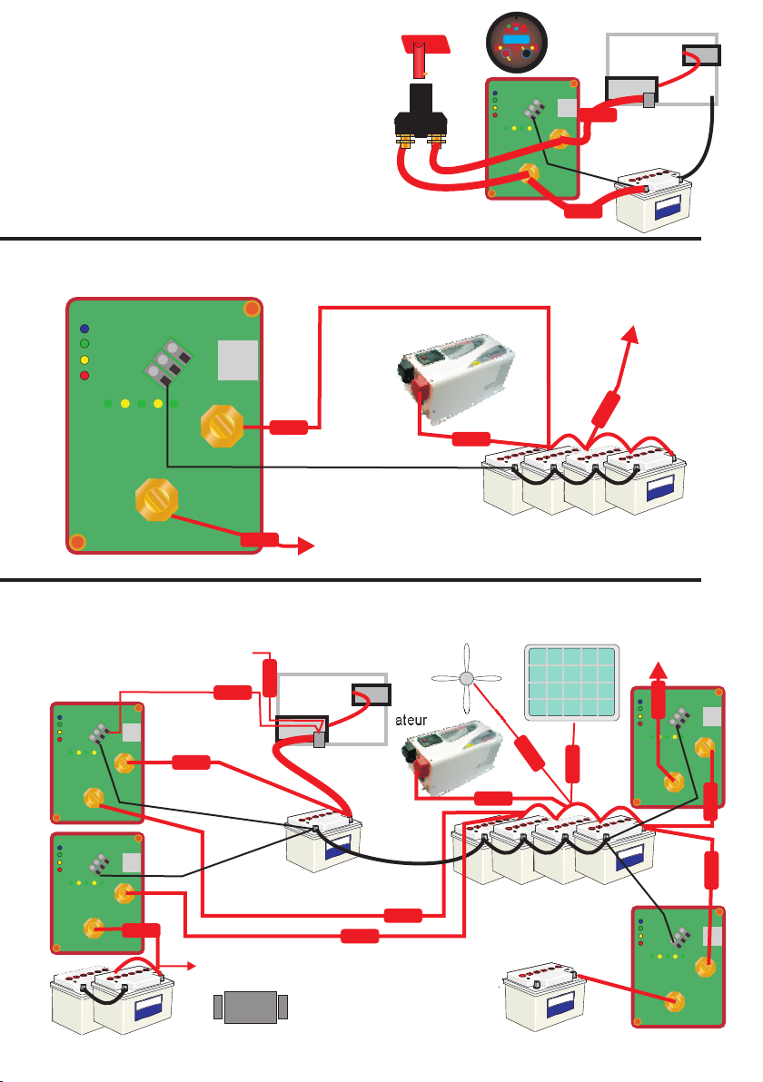
+
+
+
IN
OUT
Moteur
Démarreur
moteur
Alternateur
Solénoide
démarreur
STD
CGF
NEG
REMOTE
Utilisation mode protection. Vous pouvez souhaiter protéger des installations coûteuses,
un radar, un sonar de sur-tensions. On peut facilement les isoler dans un circuit séparé.
Suggestion de câblage
+
+
+
IN
OUT secondaire/
Batterie domestique
SDT
CFG
NG
E
REMOTE
Les câbles connectés directement à la batterie doivent être munis d ’un fusible adapté à l ’intensité;
vers lumières bateau
Vers le radar, le sonar ou
les installations coûteuses
demandant une protection en sur-tension
Protection au-dessus de 15.3 V
Si vous utilisez le relais bi-stable pour
Si la batterie est utilisée comme batterie de démarrage,
les règles européennes et américaines imposent
l ’utilisation d ’une dérivation de sécurité, en cas de
défaillance du relais.
Il suffit d ’ajouter un interrupteur manuel entre
l ’entrée et la sortie de l ’appareil pour contourner
le produit en cas d ’urgence.
Protéger une batterie isolée.
+
+
+
IN
OUT
Moteur
Démarreur
moteur
primaire/
batterie démarrage
Alternateur
Solénoide
démarreur
secondaire/ batterie Domestique
Solaire
Vent
TD
S
C G
F
N GE
REMOTE
Clé de contact
VSR
Mode charge
Système multi-usage, sur un bateau muni d ’un propulseur d ’étrave, d ’un gindeau
etc, tous les parcs batteries sont chargés par toutes les sources.
Utilisé pour charger et protéger les batteries.
Guindeau/Propulseur d ’étrave Batterie démarrage
générateur
+
+
+
IN
OUT
STD
CFG
NEG
REMOTE
Vers propulseur
étrave
+
+
+
IN
OUT
STD
CFG
NEG
REMOTE
+
+
+
IN
OUT
TDS
C GF
N G
E
REMOTE
Vers électricité
bateau
VSR
Mode charge
VSR
Mode charge
Mode protection batterie
6 mm
dia
Interrupteur
contournement
en cas d ’urgence
Sterling Power Products
Back light
Alarm
V12.6
Sleep Alarm
Closed
In
Select
Over ride
To over ride
hold for 5 sec
Audible alarm
disconnect
hold 5 sec
Latching
relay
Out
Fig 8
Fig 9
Fig 10
Fusible
Fusible
Fusible
Fusible
fusible
Fusible
Fusible
Fusible
Fusible
Fusible
Fusible
Fusible
Fusible
Fusible
Fusible
Fusible
Fusible
Fusible
This manual suits for next models
2
Table of contents
Languages:
Popular Relay manuals by other brands


Keithley
Keithley 7066 instruction manual

Velleman
Velleman VMA331 user manual

Ei Electronics
Ei Electronics RadioLINK Relay Module Ei428 instruction manual

ASO Safety Solutions
ASO Safety Solutions ELMON inductive 74-302 operating manual

Siemens
Siemens SIRIUS 3UG4501 operating instructions

GELBAU
GELBAU 252.0 Z Series original operation manual