ar
!
.
.
bg
Предупреждение: Опасно напрежение! Вижте инструкциите за работа.
Изключете и блокирайте захранването преди. да работите с
устройството. Внимание! Да се монтира само от експерт електротехник.
cs
Varování: Nebezpečné napětí! Viz návod k obsluze. Před zahájením prací
na tomto zařízení odpojte a uzamkněte napájení. Pozor! Toto zařízení smí
instalovat pouze osoba s elektrotechnickou odborností.
da
Advarsel: Farlig elektrisk spænding! Se installationsinstruktioner. Frakobl
enheden, og afbryd strømforsyningen, før du arbejder med denne enhed.
Giv agt! Installation må kun foretages af personer med elektroteknisk
ekspertise.
de
Warnung: Gefährliche Spannung! Siehe Installationsanleitung. Vor dem
Arbeiten Gerät ausschalten und von der Spannungsversorgung trennen.
Achtung! Installation nur durch elektrotechnische Fachkraft.
el
Προειδοποίηση: Επικίνδυνη τάση! Ανατρέξτε στις οδηγίες λειτουργίας.
Αποσυνδέστε και απομονώστε την παροχή ισχύος προτού ξε κινήσετε
τις εργασίες σε αυτήν τη συσκευή. Προσοχή! Η εγκατάσταση πρέπει να
γίνεται μόνο από αδειούχο ηλεκτρολόγο εγκαταστάτη.
en
Warning: Hazardous voltage! Refer to installation instructions. Disconnect
and lock out power before working on this device. Attention! Installation by
person with electrotechnical expertise only.
es
Advertencia: ¡Tensión peligrosa! Consulte las instrucciones de instalación.
Antes de trabajar con este dispositivo, desconecte y bloquee la corriente.
¡Atención! La instalación debe ser realizada únicamente por un técnico
electricista.
et
Hoiatus: Elektrilöögi oht! Lisateavet vaadake kasutusjuhendist. Enne selle
seadmega töötamist ühendage lahti ja lukustage toide. Tähelepanu! Seadet
tohib paigaldada ainult elektrotehnilise kogemusega isik.
fi
Varoitus: Vaarallinen jännite! Katso asennusohje. atkaise virta ja estä virran
kytkeminen lukituksella ennen töiden aloittamista. Huomio! Asennuksen
saa suorittaa vain henkilö, jolla on kokemusta sähkötekniikasta.
fr
Avertissement: Tension dangereuse! Consultez les consignes d’installation.
Débranchez et verrouillez l’alimentation électrique avant d’entreprendre
des travaux sur cet appareil. Attention! L’installation doit être effectuée
uniquement par une personne ayant une expertise en électrotechnique.
hr
Upozorenje: Opasan napon! Pogledajte upute za ugradnju. Odspojite i
isključite struju prije rada na ovom uređaju. Pažnja! Ugradnja je dopuštena
samo osobama stručnim u području elektrotehnike.
hu
Figyelmeztetés: Veszélyes feszültség! Lásd a használati utasítást. Válassza
le és zárja ki az áramellátást, mielőtt a berendezésen dolgozni kezd.
Figyelem! Az üzembe helyezést csak elektrotechnikai szakértelemmel
rendelkező személy végezheti el.
it
Attenzione: Tensione pericolosa! Fare riferimento alle istruzioni per l’uso.
Prima di intervenire su questo dispositivo, scollegare e isolare tutte le
fonti di alimentazione. Attenzione! L’installazione deve essere eseguita
esclusivamente da un installatore qualificato.
lt
Įspėjimas: Pavojinga įtampa! Žr. naudojimo instrukcijas. Atjunkite ir laikinai
užblokuokite maitinimą prieš dirbdami su šiuo įrenginiu. Dėmesio! Įrengti
gali tik asmuo, turintis elektrotechniko patirties.
lv
Brīdinājums: Bīstams spriegums! Skatiet darba norādījumus. Pirms sākat
darbu ar šo ierīci, atvienojiet un bloķējiet strāvas padevi. Uzmanību!
Uzstādīšanu drīkst veikt tikai persona ar zināšanām par elektrotehniku.
nl
Waarschuwing: Gevaarlijke spanning! Raadpleeg de installatie-
instructies. Koppel dit apparaat los van de stroomvoorziening voordat u
werkzaamheden uitvoert. Let op! Installatie mag alleen worden uitgevoerd
door een monteur met elektrotechnische expertise.
no
Advarsel: Farlig spenning! Se i bruksanvisningen. Koble fra og steng av
strømmen før du arbeider på denne enheten. Forsiktig! Montering skal kun
utføres av kvalifiserte personer med elektrokompetanse.
pl
Ostrzeżenie: Niebezpieczne napięcie! Patrz: instrukcja instalacji. Przed
rozpoczęciem wykonywania pracy z tym urządzeniem odłącz i zablokuj
zasilanie. Uwaga! Montaż może wykonywać wyłącznie osoba posiadająca
doświadczenie elektrotechniczne.
pt
Aviso: Tensão perigosa! Consulte as instruções de instalação. Desconecte
e desligue a energia elétrica antes de trabalhar nesse dispositivo. Atenção!
A instalação deve ser feita apenas por uma pessoa com especialidade
eletrotécnica.
ro
Avertisment: Tensiune electrică periculoasă! Consultați instrucțiunile de
utilizare. Deconectați și închideți sursa de energie înainte de a lucra cu acest
dispozitiv. Atenție! Instalarea trebuie realizată doar de către o persoană cu
expertiză electrotehnică.
ru
Предупреждение: Опасное электрическое напряжение! Обратитесь
к инструкциям по монтажу. Отключите электропитание и обеспечьте
безопасность перед началом работ. Внимание! Монтаж должен
выполняться только специалистом по электротехническим работам.
sk
Výstraha: Nebezpečné napätie! Pozrite si návod na použitie. Pred začatím
prác na tomto zariadení odpojte a zablokujte napájanie. Pozor! Inštaláciu
smie vykonávať len osoba s odbornými znalosťami v oblasti elektrotechniky.
sl
Opozorilo: Nevarna napetost! Glejte navodila za uporabo. Pred delom na tej
napravi izklopite in zaklenite električno napajanje. Pozor! Namestitev sme
izvesti samo elektrotehnični strokovnjak.
sv
Varning: Livsfarlig spänning! Se i bruksanvisningen. Frånkoppla och
blockera anläggning eller en anläggningsdel innan arbete utförs. Obs! Får
endast installeras av behörig elektriker.
tr
Uyarı: Tehlikeli gerilim! Montaj talimatlarına bakın. Bu cihaz üzerinde
çalışmadan önce elektriği kesin ve kilitleyin. Dikkat! Yalnızca elektroteknik
uzmanlığa sahip kişiler tarafından kurulabilir.
zh 警告:高压危险! 请参见操作手册。操作本设备前请断开并锁定电源。注意!安
装仅限专业电工人员。
Doc.no. 1SVC 730 050 M1000 A (03/22)
—
SAFETY INSTRUCTIONS
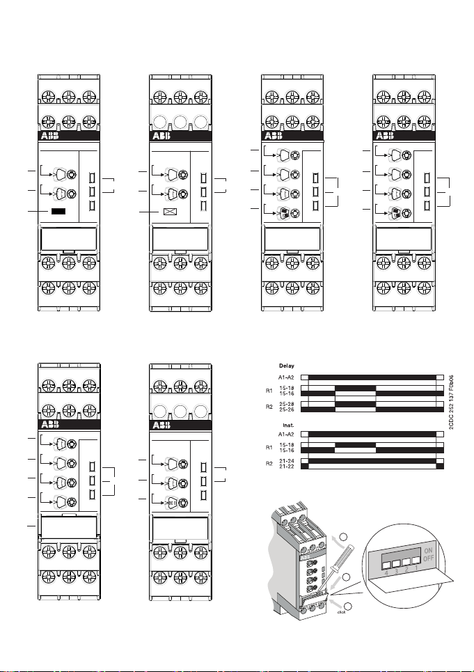
CT-AHS, CT-APS, CT-ARS, CT-ERS, CT-MBS,
CT-MFS, CT-MVS, CT-MXS, CT-SDS, CT-WBS
Time relays
Page 1/25