PAW HeatBloC K34R User manual

PAW GmbH & Co. KG
Böcklerstr. 11, 31789 Hameln - Germany
Phone: +49-5151-9856-0, Fax: +49-5151-9856-98
E-mail: [email protected], Web: www.paw.eu
2021/07 993x0663Mx-mub-en – V01 1
DN 25
DN 32
Installation and Operation
Instructions
HeatBloC® K34R
DN 25 / DN 32

1General Information
2 993x0663Mx-mub-en – V01 2021/07
Item no. 993x0663Mx-mub-en – Version V01 – Issued 2021/07
Translation of the original instructions
We reserve the right to make technical changes without notice!
Printed in Germany – Copyright by PAW GmbH & Co. KG
PAW GmbH & Co. KG
Böcklerstraße 11
31789 Hameln - Germany

1General Information
2021/07 993x0663Mx-mub-en – V01 3
Contents
1General Information.........................................................................................................4
1.1 Scope of these instructions ..........................................................................................4
1.2 Designated use ............................................................................................................4
2Safety instructions ...........................................................................................................5
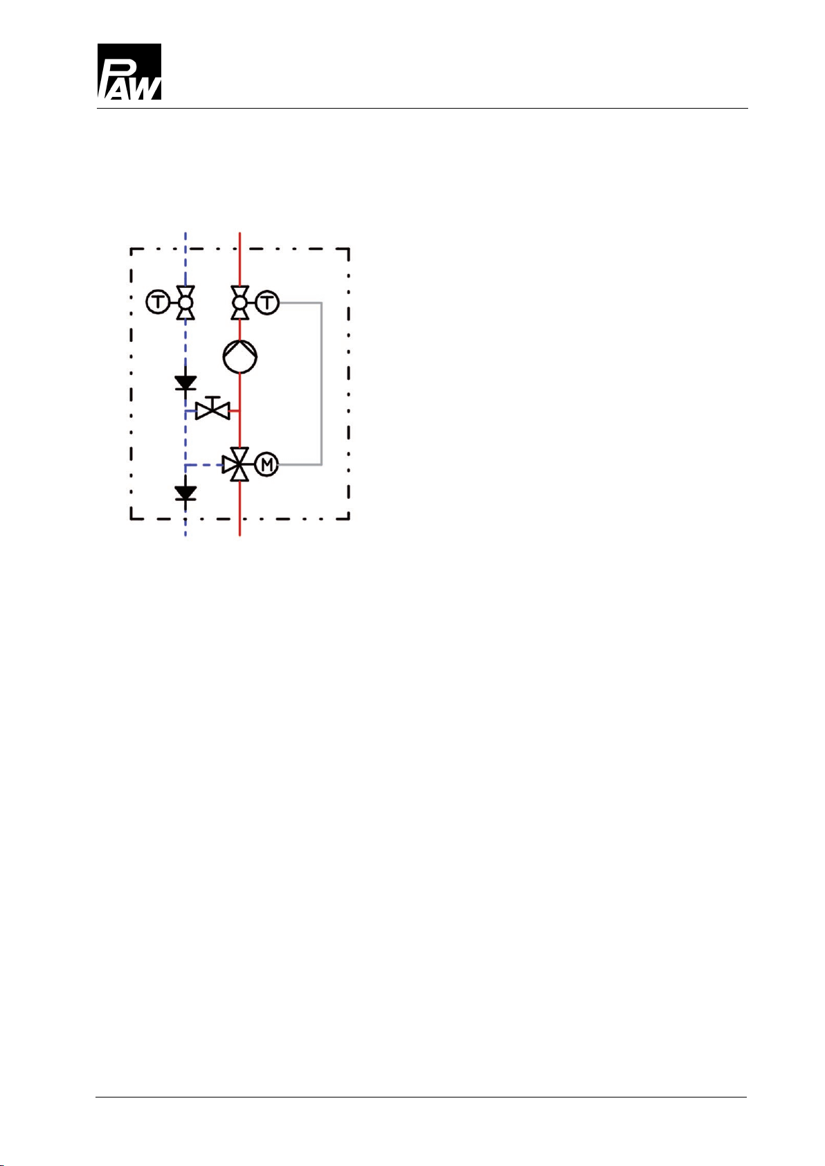
3Product description..........................................................................................................6
3.1 Equipment....................................................................................................................7
3.2 Function .......................................................................................................................8
3.2.1 Check valve and non-return valve .......................................................................10
3.2.2 Pump [specialist].................................................................................................11
3.2.3 3-way mixing valve [specialist] ............................................................................11
3.3 Weather compensated controller PWR6.....................................................................15
3.4 Settings for the weather compensated controller PWR6 when used as return flow
temperature maintenance .....................................................................................................15
3.5 Installation of the weather compensated controller PWR6..........................................16
4Mounting and installation [specialist] ..............................................................................17
4.1 Installation and commissioning of the HeatBloC® ......................................................17
4.2 Accessories: Cutting-ring compression fitting (not included in the scope of delivery).. 20
5Scope of delivery [specialist]..........................................................................................21
5.1 Spare parts DN 25 .....................................................................................................21
5.2 Spare parts DN 32 .....................................................................................................23
6Technical data...............................................................................................................25
6.1 Pressure drop and pump characteristic curves DN 25................................................ 26
6.2 Pressure drop and pump characteristic curves DN 32................................................ 26
7Disposal........................................................................................................................27

1General Information
4 993x0663Mx-mub-en – V01 2021/07
1General Information
Carefully read these instructions before installation and commissioning. Save these
instructions in the vicinity of the installation for future reference.
1.1 Scope of these instructions
These instructions describe the installation, commissioning, function and the operation of the
mixed HeatBloC® K34R DN 25 and DN 32.
For other components of the installation, such as the pump, the controller or the modular
distribution manifold, please observe the instructions of the corresponding manufacturer.
The chapters called [specialist] are intended for specialists only.
1.2 Designated use
The HeatBloC® may only be used in heating circuits taking into consideration the technical limit
values indicated in these instructions.
The HeatBloC® must not be used in drinking water applications.
Improper usage of the HeatBloC® excludes any liability claims.
This product complies with the relevant directives and is therefore labelled with the CE mark.
The Declaration of Conformity is available upon request, please contact the manufacturer.
Only use PAW accessories with the HeatBloC®.

2Safety instructions
2021/07 993x0663Mx-mub-en – V01 5
2Safety instructions
The installation and commissioning as well as the connection of electrical components require
technical knowledge commensurate with a recognised vocational qualification as a fitter for
plumbing, heating and air conditioning technology, or a profession requiring a comparable level
of knowledge [specialist].
The following must be observed during installation and commissioning:
•relevant local and national regulations
•accident prevention regulations of the professional association
•instructions and safety instructions mentioned in these instructions
CAUTION
Personal injury and damage to property!
The HeatBloC® must only be used in heating circuits filled with heating water
according to VDI 2035 / Ö-Norm H 5195-1.
The HeatBloC® must
not
be used in drinking water applications.
ATTENTION
Material damage due to mineral oils!
Mineral oil products cause lasting damage to seals made of EPDM, whereby the sealant
properties are lost. We do not assume liability nor provide warranty for damage to property
resulting from sealants damaged in this way.
It is imperative to prevent the EPDM sealing elements from making contact with
substances containing mineral oils.
Use a silicone- or polyalkylene-based lubricant free of mineral oil such as Unisilikon
L250L and Syntheso Glep 1 from Klüber or a silicone spray.

3Product description
6 993x0663Mx-mub-en – V01 2021/07
3Product description
The HeatBloC® K34R is a preassembled group of fittings for heating circuits. The pump can be
isolated by means of the ball valves and the mixing valve. The pump can thus be maintained
easily without draining the heating circuit system.
The HeatBloC® is designed such that it can be directly mounted onto a PAW distribution
manifold or a mounting plate.
With transition connections, the HeatBloC®s can also be mounted on modular distribution
manifolds of other dimensions.
The HeatBloC® K34R is prepared for the operation as a supply group for various heating
applications, such as for panel heating systems or radiator circuits - with a flow temperature that
always reacts to the variable weather conditions. The bypass of the mixing valve can,
depending on the application and the heat generator, be completely opened (e.g. radiant floor
heating) or partly closed (radiators). An external sensor as well as a source sensor are included
in the scope of delivery, which allow to use the weather compensated flow temperature.
The HeatBloC® K34R can be easily converted into a group for return flow temperature
maintenance or to a controlled circuit with constant value.
Optionally, a room control unit can be connected to the PWR6 which allows a more detailed
control of the flow temperature.

3Product description
2021/07 993x0663Mx-mub-en – V01 7
3.1 Equipment
A-1 Flow to the consumer circuit
A-2 Full metal thermometer with immersion
sleeve, integrated in the ball valve (flow)
B Heating pump
C 3-way mixing valve with adjustable
bypass 0-50 %
C-1 Flow from the heat generator
C-2 Return to the heat generator
C-3 Non-return valve, can be opened
C-4 Weather compensated controller PWR6
D-1 Check valve, can be opened
D Return pipe
E Design insulation with optimised function
F-2 Full metal thermometer with immersion
sleeve, integrated in the ball valve (return)
F-1 Return from the consumer circuit

3Product description
8 993x0663Mx-mub-en – V01 2021/07
3.2 Function
K34R: 3-way mixing valve with bypass 0-50 %
The flow temperature of the heating circuit is
controlled by the integrated mixing valve.
Hot water from the boiler and cold return water are
mixed to obtain the desired flow temperature of
the heating circuit. The mixing valve is adjusted by
means of the weather compensated controller
PWR6.
Due to the premixing rate that must be adjusted at
the bypass of the mixing valve, a certain amount of
cold return water is added to the flow water.
The 3-way actuator can thus work over the whole
adjustment range (0-100 %), although only a small
amount of water from the boiler is necessary.
Example:
Panel heating systems
operate on a low temperature
level with small temperature differences, but with
high flow rates.
It is therefore sufficient to add a small amount of hot
water to the "warm" return water.
For the use as a
return flow temperature
maintenance
, the bypass in the mixing valve must be
completely closed so that the entire boiler output is
available for the consumer circuits.

3Product description
2021/07 993x0663Mx-mub-en – V01 9
Application range:
•Consumer circuits with weather compensated
low-temperature heating systems controlled
by a mixing valve
•Consumer circuits with high flow rates,
e.g. radiant floor heating and radiant panel
heating systems
•Return flow temperature maintenance
(then, bypass is closed)

3Product description
10 993x0663Mx-mub-en – V01 2021/07
3.2.1 Check valve and non-return valve
The HeatBloC® is equipped with a check valve (D-1, opening pressure 200 mm wc) in the
return pipe and with a non-return valve (C-3, opening pressure 50 mm wc) in the return of the
mixing valve. The valves can be opened.
Operation
During operation, the markings must point to "Z".
The check valve and the non-return valve are closed.
Flow only in the direction of the arrow.
Filling, draining, venting
For filling, draining and venting, the markings must be directed
to "A".
The check valve and the non-return valve are open.
Flow in both directions.

3Product description
2021/07 993x0663Mx-mub-en – V01 11
3.2.2 Pump [specialist]
The pump can be completely isolated. It can be replaced and maintained without draining the
heating circuit system.
Isolation of the pump:
1. Disconnect the expansion tank from the installation.
2. Close the ball valves in the flow and the return (A-2, F-2).
3. Remove the controller PWR6 from the mixing valve.
4. Turn the bypass screw of the mixing valve such that the slot is in a vertical position.
5. Turn the nose of the valve cock such that the flow to the pump is closed (for flow on the
right: nose points downward, for flow on the left: nose points to the right; see below).
The mixing valve is now closed and drop tight.
3.2.3 3-way mixing valve [specialist]
The 3-way mixing valve (C), driven by an electric actuator, adjusts the flow temperature of the
consumer circuit to the required value by means of the flow sensor and the controller.
The mixing valve is equipped with a bypass which must be operated separately. Via this
bypass, cold return water is added to the flow of the HeatBloC®. This can result in an increase
of the flow rate of the HeatBloC®.
Mixing valve with flow on the right:
Position
10
and
bypass
closed:
Passage, no mixing, flow
temperature consumer = flow
temperature boiler
Position
0
: 100% mixing flow
temperature consumer =
return temperature consumer
10
0
Flow of the pump closed

3Product description
12 993x0663Mx-mub-en – V01 2021/07
1. During commissioning, determine the optimum bypass position for the operation of the
installation. Find out and check the correct adjustment through a trial-and-error process.
If the slot of the bypass screw is in a
vertical position, the bypass is closed.
If the HeatBloC® K34R is used as a
return flow temperature maintenance,
the bypass must be closed!
If the slot of the bypass screw is in a
horizontal position, the bypass is
completely open. A maximum flow rate
from the return to the flow line is thus
enabled. This adjustment may be
necessary for radiant floor heating
systems which require a very high
water flow volume. Because of the
bypass, the flow temperature
decreases and the control is affected.
2. Check the position of the bypass during operation. Make sure that the flow rate is
sufficient and that the desired temperature is reached.

3Product description
2021/07 993x0663Mx-mub-en – V01 13
Change of the flow line [specialist]
Dismounting of the mixing valve
1. Take off the thermometer handles (A-2, F-2) and remove the insulating front shell.
2. Take the group of fittings out of the insulating back shell.
3. Dismount the mixing valve (C).
Retrofitting of the mixing valve
1. Loosen the screw (1).
2. Take off the rotary knob (2) from the cock rod.
3. Loosen the screws (3).
4. Remove the cover plate (4).
5. Loosen the two screws (5).
6. Remove the front plate (6).
7. Extract the sealing bush (7) with the cock plug (8) from the housing of the mixing valve.
8. Loosen the screws (10) on the rear side of the mixing valve.
9. Take off the cover (9) on the rear side of the mixing valve and fix it on the other side of
the mixing valve by using the screws (10).
10. Insert the sealing bush (7) with the cock plug (8) into the channel of the mixing valve.
11. Screw down the front plate (6) using the screws (5).

3Product description
14 993x0663Mx-mub-en – V01 2021/07
12. Turn the cover plate (4) in such a way that the marking "PAW" is at the bottom (in
direction of the external threads) and that the scale is positioned as shown in the figure
above.
13. Fix the cover plate (4) by using the screws (3).
14. Put the rotary knob (2) onto the cock rod and turn the cock plug to the mixing valve
position "5". Then, the controller PWR6 can directly be mounted.
15. Fix the rotary knob (2) on the cock plug (8) by using the screw (1).
Retrofitting and commissioning of the heating circuit
1. Interchange the return pipe (D) and the flow pipe with the pump (B).
Consider the flow direction of the pump!
Turn the pump head such that the terminal box is directed to the top or to the centre of the
group of fittings.
2. Dismount and interchange the ball valves. The temperature sensor must be mounted in
the flow ball valve!
3. Mount the HeatBloC® and connect it to the installation.
4. Check all union nuts before commissioning and firmly tighten them if necessary.
5. Mount the insulation only after having carried out a pressure test.
Mount the thermometer handles (A-2, F-2) in a final step.
Mixing valve with flow on the right
Mixing valve with flow on the left
Flow
Flow

3Product description
2021/07 993x0663Mx-mub-en – V01 15
3.3 Weather compensated controller PWR6
The weather compensated controller PWR6 is prepared for the direct mounting onto the
3-way bypass mixing valve of the HeatBloC® K34R.
If the controller is connected to the power supply for the first time, an initial commissioning must
be carried out. The commissioning is carried out automatically in four steps: language selection
- selection of the hydraulic scheme (area, radiator,...) - gradient of the heating curve - opening
direction of the actuator of the mixing valve.
When the controller is delivered, the default settings are: German - radiator heating - 0.7 -
at the right
3.4 Settings for the weather compensated controller PWR6 when used as return flow
temperature maintenance
Application
Flow line
required modifications at
the HeatBloC®
required settings at the
controller PWR6 - see
separate instructions
radiant panel
heating
pump on the
right, transports
upwards
-
•if necessary, adjust
hydraulic scheme and
heating curve
pump on the left,
transports
upwards
•retrofitting of the mixing
valve and of the
HeatBloC® for flow on
the left
(see 3.2.2 and 3.2.3)
•change the direction of
rotation to "left"
•if necessary, adjust
hydraulic scheme and
heating curve
radiator heating
pump on the
right, transports
upwards
•close mixing valve
bypass partly or
completely
-
pump on the left,
transports
upwards
•retrofitting of the mixing
valve and of the
HeatBloC® for "flow" on
the left
(see 3.2.2 and 3.2.3)
•close mixing valve
bypass
•change the direction of
rotation to "left"

3Product description
16 993x0663Mx-mub-en – V01 2021/07
3.5
Installation of the weather
compensated controller PWR6
for mixing valve with flow on the right:
1. Turn the rotary knob
of the mixing valve into position "
5
".
2. When the weather compensated controller
is delivered, it is in centre position.
By disengaging the gear (●push○), you can
adjust the controller at the rotary knob. In
this way, you can test if the actuator / rotary
knob is mounted correctly.
3. Mount the stop bolts, if necessary.
4. Push the weather compensated controller
PWR6 on the rotary knob of the mixing
valve and mount it onto the two stop bolts
(fig. 1).
The weather compensated controller must
be mounted according to figure 2.
5. Re-engage the gear (●push○).
6. Set the controller to automatic operation
mode.
7. Mount the flow contact sensor, the external
sensor and the source sensor (immersion
sensor). Connect these with the controller.
8. If a room control unit is available, it also
must be connected to the controller via a
bus line).
9. After the mounting is completed, the safety
plug can be plugged into a corresponding
socket (fig. 3).
10. For the commissioning, please observe the
instructions of the controller.
Stop bolts
Fig. 2
Fig. 3
safety plug
Fig. 1

4Mounting and installation [specialist]
2021/07 993x0663Mx-mub-en – V01 17
4Mounting and installation [specialist]
The HeatBloC® K34R can be mounted on a PAW modular distribution manifold or on a wall
bracket. The modular distribution manifold and the wall bracket are optional accessories and
are thus not included in the scope of delivery.
ATTENTION
Damage to property!
The installation site must be dry, stable, frost-proof and protected against ultraviolet radiation in
order to prevent material damage of the installation.
4.1 Installation and commissioning of the HeatBloC®
The HeatBloC® can be mounted
•
Option 1:
on a PAW modular distribution manifold.
flow
flow
heat generator
return
return
consumer circuit

4Mounting and installation [specialist]
18 993x0663Mx-mub-en – V01 2021/07
•
Option 2:
on a mounting plate with
transition thread connections.
•
Option 3
: directly on a wall bracket.
Please observe the separate and respectively corresponding instructions regarding the
installation of the distribution manifold, of the mounting plate and of the wall bracket.
flow
flow
return
return
heat generator
consumer circuit
return
return
flow
flow

4Mounting and installation [specialist]
2021/07 993x0663Mx-mub-en – V01 19
1. Take off the thermometer handles (A-
2, F-2) and remove the insulating front
shell of the HeatBloC®.
2. Unscrew the nuts on the lower
connections of the HeatBloC® and
take out the sealing rings.
If a PAW modular distribution manifold or
transition connection is used:
3. Put the two nuts over the flanges.
4. Insert the sealing rings into the nuts.
5. Put the HeatBloC® onto the two nuts.
6. Tighten the nuts.
Make sure that the nuts do not get
jammed and that the sealing rings do
not slip.
7. Connect the HeatBloC® to the
installation by using the pipes. The
installation to the piping must be
carried out without any tension.
8. Connect the pump.
9. Carry out a pressure test and check
all thread connections.
10. Mount the insulating front shell and
the thermometer handles (A-2, F-2).
flange
(top view)
nut
1
2
3
flange
(side view)
sealing ring

4Mounting and installation [specialist]
20 993x0663Mx-mub-en – V01 2021/07
4.2 Accessories: Cutting-ring compression fitting (not included in the scope of delivery)
The connection to the heating installation can be carried out fast, pressure-proof and without
soldering if you use the optionally available compression fittings.
Not included in the scope of
delivery!
1. Push the union nut ② and the cutting ring ③ onto the
copper pipe ①. The pipe must protrude at least 3 mm
from the cutting ring in order to ensure the force
transmission and the sealing.
2. Insert the support sleeve ④ into the copper pipe.
3. Insert the copper pipe with the plugged-on individual
parts (②, ③ and ④) as far as possible into the body
of the compression fitting ⑤.
4. First, screw the union nut ② manually.
5. Tighten the union nut ② by rotating one full turn.
Secure the body of the compression fitting ⑤ against
distort in order to avoid damaging the sealing ring.
Other manuals for HeatBloC K34R
1
This manual suits for next models
2
Table of contents
Other PAW Water System manuals
Popular Water System manuals by other brands

Zip
Zip HydroTap BCS Compact series installation instructions

Kenmore
Kenmore 625.384450 owner's manual

Ultimate Solar
Ultimate Solar 1K HE3 Installation and user manual

Binder
Binder HydroStar BGA 160 operating instructions

Presto
Presto Q4357 installation instructions

Viking Pure
Viking Pure Mini Pure VPM user manual

Hoval
Hoval HSP Installation and operating instructions

Sartorius
Sartorius arium mini plus operating instructions

Tuxhorn
Tuxhorn tubra-PGS XL Assembly and operating instructions

Sears
Sears 390.250095 owner's manual

EINHELL
EINHELL GE-AW 1042 FS Original operating instructions

ELwell
ELwell Timberline user manual