PAXSTER Hardtop User manual

USER MANUAL
-EN-UK-
Paxster Hardtop –Generation 2.0

2
Table of Contents
Foreword ................................................................................................................................................. 3
About this manual ................................................................................................................................... 3
Warranty ................................................................................................................................................. 4
Modifications........................................................................................................................................... 4
Keys ......................................................................................................................................................... 4
Vehicle Identification............................................................................................................................... 5
Safety instructions................................................................................................................................... 6
Ignition lock ............................................................................................................................................. 6
Range and driving behavior..................................................................................................................... 7
The batteries, the battery charger and the charging process................................................................. 8
Instruments and switches ..................................................................................................................... 11
Overview of the driver’s immediate anterior environment.............................................................. 11
Overview of the driver’s immediate posterior environment............................................................ 11
Hand control on the left side............................................................................................................. 12
Hand control on the right side .......................................................................................................... 12
Main instrument panel...................................................................................................................... 13
Changing modes on the main instrument panel............................................................................... 13
Control panel..................................................................................................................................... 14
Parking brakes ....................................................................................................................................... 15
Driving instructions ............................................................................................................................... 16
Cargo zones ........................................................................................................................................... 17
Do it yourself - maintenance................................................................................................................. 18
FAQ ........................................................................................................................................................ 20
Daily check of the vehicle...................................................................................................................... 21
Technical specifications......................................................................................................................... 22
Recommendation to driver’s safety:..................................................................................................... 23
Optional Equipment List........................................................................................................................ 23

3
Foreword
Congratulations for your new Paxster!
On behalf of Paxster AS I would like to congratulate you as a driver of the completely unique Paxster.
Paxster is a unique new electric vehicle, designed for maximum efficiency when making deliveries.
With a high payload, long range, excellent road performance and optimal user ergonomics, we think
that Paxster stands out as “the ultimate electric delivery vehicle”.
It is very important to us at Paxster AS that you as a delivery worker have a good and efficient work
day as possible. Therefore, I hope that you will find Paxster to be a decent work tool, which will help
you perform your tasks in the best way possible. I wish you good luck in your use of Paxster!
With kind regards,
Paxster AS
Lasse A. Hansen
Managing Director
About this manual
This user’s manual explains how you can quickly make use of this vehicle and use it in a way that
takes care of both your safety and the vehicle’s technical condition.
In addition, it explains normal use and maintenance that can be performed by the individual
operator. For major maintenance or problems, contact your local or national service provider printed
on back of this manual.
Correct maintenance and use of this vehicle will help give you maximum pleasure and utility as a
user, and it will also help reduce operating and maintenance costs. This will also increase the value
upon the resale of the vehicle.
NOTE: Estimated time to read the manual: 30 minutes.

4
Warranty
Warranty terms and conditions are presented in the purchase contract between Paxster AS and the
Buyer. The warranty does not cover normal wear and tear parts, or consumables that will naturally
need to be replaced during the vehicle’s lifetime.
Modifications
Paxster is a technically advanced vehicle. If there is a need for repairs or other assessment of
malfunctions, please contact your local- or national service provider printed on the back of this
manual.
This vehicle is designed and type-approved so that it shall comply with current rules in the relevant
country. Changes performed by the operator may result in changes that mean that the vehicle is no
longer in accordance with the original approval. This entails that the operator him-/herself is
responsible for the malfunction and/or reactions that may occur. Therefore, you should never make
changes in components that can increase the motor’s performance or the vehicle’s speed.
Keys
The vehicle is delivered with a unique set of keys. In each set of keys, there are also spare keys. We
recommend that these are stored separately from the ones in daily use.
The following keys are delivered with the vehicle:
• Key to the ignition lock
• Key to the rear cargo hold
• Key for the side cargo compartments
If you should lose the keys, you must read off the identification number of the vehicle and order a
new key from the manufacturer. There are also possible to order “blank-keys” to make extra spare-
keys. Separate prices will be charged in accordance with prices agreed between Buyer and the
manufacturer.
NOTE: Remember to oil the locks in the winter to keep them from freezing shut.

5
Vehicle Identification
Chassis number
The vehicle’s chassis number (VIN) is engraved into the front chassis structure on the right side.
The manufacturer’s data plate
The manufacturer’s data plate contains the vehicle’s identification number (VIN), and type-approval.
The data plate is located under the seat on the left side.
Registration number
The vehicle’s registration number is located below the cargo zone in the rear of the vehicle, just as on
an ordinary car.
NOTE: To get correct spare-parts for your vehicle, always use chassis number (VIN) as identification.

6
Safety instructions
Paxster is electrically powered. This is a different technology than internal combustion engines and
therefore requires a different attention. If you pay attention to the points described below, you will
safeguard both yourself and the vehicle.
Caution when handling charger and battery
All handling of the vehicle’s battery charger shall be performed with great caution. Opening the
battery compartment beneath the saddle seat should be exclusively performed by qualified service
personnel.
Hazardous voltage
During charging, there will be voltage in the battery charger that can cause personal hazard.
Alterations to the battery charger must therefore only be performed by qualified service personnel.
Grounded contact
The battery charger shall only be plugged into a grounded wall socket with 10 A of current.
Check of cables
Regularly check that the battery charger’s cables are undamaged.
WARNING: In the event of damage to a cable or charger, the damaged part shall not be used.
Contact qualified service personnel.
Ignition lock
The ignition lock has three positions: PARK/ON/OFF. The position lights functions in PARK mode.
To activate all other lights, the ignition must be activated (see instrument panel).
NOTE: Steering- lock have become mandatory from 1/1-2018.

7
Range and driving behavior
The vehicle’s range is determined by several factors. As the operator, you will have considerable
effect on the vehicle’s range through your driving behavior. By active use of the regenerative brake,
you extend the vehicles range.
The theoretical range of Paxster is in the interval of 40-100 km or 4-10 hours of active mail/parcel
distribution. Higher speed means higher energy consumption.
Note: Actual range depends on factors such as topography, load, driving style, climatic conditions etc.
Three different traction-battery-packs are available:
100Ah –5,1kWh –40-60km –4-6 hours
180Ah –8,1kWh –50-90km –5-9 hours
180Ah –9,2kWh –60-100km –6-10 hours
Driving in snow or loose-soil, will increase the energy consumption due to increased rolling friction. It is
important that you economise energy as you drive in order to optimise the range. Regeneration,
however, must be used with caution on slippery roads (see “choice of driving mode on page 15).
Always use both of the brakes on slippery roads. A transition from spinning wheels on a slippery
surface, to good grip on the road, will cause unnecessarily wear on the motor and transmission. This
kind of damage is not covered by the warranty.
In general, we recommend the following driving pattern:
Smooth acceleration
Mechanical brakes are used to support the regenerative brake (motor brake). Important for
less wear on brake components and maximized autonomy is to use the regenerative brake
actively.
Adapt the speed and reduce the need for braking.
To avoid unnecessary wear of brakes, use both the front and back brakes.
Do not use high-energy-consuming equipment with the 12 Volt AUX-socket.
Limit the use of heating wires in the front windscreen. This is ONLY meant for de-icing. A
timer switch will de-activate heating wires after 15 minutes of use.
Limit the use of heated grips (if such equipment is available on your vehicle).
Make sure you have correct air pressure in all tires (1.8 to 2.1 bars), this to reduce rolling
friction and maintain a good grip.

8
Tips when starting on a steep hill:
• Place the vehicle in Power-mode.
• Hold the rear brake (left lever) in at the same time as you turn up the throttle, then release the brake.
If the vehicle is released backward before you turn up the throttle, you will use considerably more energy getting
under way. Because of the vehicle’s power limitations, a reduction in top-speed may occur when climbing hills,
especially if the vehicle is fully loaded.
The batteries, the battery charger and the charging process
The traction-battery
The vehicle has a battery-pack that consists of several cells and a heating system. These components are
controlled by an electronic battery management system (BMS). The BMS optimizes and maintain the traction-
battery’s performance and health. The battery-cells are of Lithium-type, designed for use in electric vehicles.
The battery-cells have the designation LiFePO4, or so called LFP batteries.
Daily charge
It is recommended that you start the charging process immediately after the work day is over. A good routine
on this also prevents unwanted problems the next day. As a general rule, you should charge the batteries as
often as possible. A discharge is not necessary before you connect or reconnect the battery-charger. To extend
daily range, connect the vehicle to the battery charger also during shorter stops, like lunch-brake.
Repeated deep discharge
Avoid deep discharge of the traction-battery. This will have a negative impact on the traction-battery’s capacity
and life time. For long-time storage keep the battery at about 80%.
Protection mode
If the voltage in the traction-battery becomes too low, the BMS system ensures that the vehicle is set in
“protection mode”. As a result, you will not be able to continue driving at a normal speed. The vehicle must be
returned to the terminal for a complete charging cycle. Pay careful attention to the battery indicator, and abort
delivery-route if necessary.
The traction-battery and winter use
To keep as short charge-cycle as possible, we recommend storing vehicles indoor in a nonfreezing environment. If
stored in temperatures below zero, we recommend keeping the vehicles continuously connected to charger.
Charging batteries in cold weather will increase charging time. Depending on size and temperature, the heater
might need hours to warm the battery before normal charging process will start.

9
NOTE: The charger must be plugged in to the vehicle for the battery heater to function. At temperatures above
55 degrees Celsius, the battery pack will automatically be shut off to avoid damage to the batteries and vehicle.
The charger
An energy-efficient, maintenance-free 230V battery charger comes with the vehicle. The battery
charger must be connected to a grounded wall socket belonging to a circuit of at least 10A.
Charging time
The charging time is highly variable and depends on several factors. Under optimal conditions, the
charging time for completely discharged batteries is about 5 - 10 hours, depending on size of battery
pack. If the batteries are kept frozen, the charging time will be extended by up to 5 hours before
normal charging starts. The charging time will be reduced if you charge at room temperature, and
the batteries are not completely discharged.
We advise you to plug the charger in as soon as the vehicle is in the house at the end of a workday so
that the batteries can be charged for as long as possible. It is also recommended that the charger is
kept plugged in during the weekend so that the batteries will get a proper balancing at least once a
week.
Note: If the vehicle is not in use for a long period of time, it is important that it remains connected to the
charger, or the 30A main-fuse on steering-column fuse-box is removed. This prevents the batteries voltage to
drop. Leaving drained batteries for a long time, will be detrimental to the batteries’ lifetime.
The functioning of the charger
With regard to reading off the charge status, we recommend that you pay attention to the light
signals in the charge cable symbol on the vehicle’s main instrument panel. The symbol has a green
LED that blinks 1-4 times within a 2-second interval.
The blinking-pattern will tell you in what stage the charger operates, if there’s an error, or if the
charge-cycle is finished.

10
The signals should be interpreted in the following way:
1 pulse: Pre-heating. This means that the battery is too cold, and the battery heater has been activated. The
BMS system waits until the battery has reached charge temperature.
2 pulses: Pre-charge. Pre-charge is something that happens if the battery is completely discharged. In that
case, you need to charge with a low current until all of the cells have reached a certain voltage. This is also
controlled by the BMS system.
3 pulses: Main charging. In this charging cycle, full power is sent from the charger to the battery.
4 pulses: Balancing. This phase of charging can take very little time, or it can take several hours, depending on
the voltage in the different battery cells. The battery management system (BMS) ensures that all battery-cells
have the same voltage when they are fully charged to ensure the maximum capacity in the battery. If
necessary, the charger can be disconnected before the balancing is done, but it is recommended that this
process be run through at least once a week, e.g. during the weekend.
When the charging is completed, the battery symbol flashes slowly.
If the charging process malfunctioned, the battery symbol will flash rapidly. Contact your service provider.
How to charge the vehicle
It is strongly recommended that the charger is permanently fastened to the wall, to avoid damage to the
equipment. The charger is delivered with an extended cable in order to reach from the charger socket to the
vehicle.
1. Always plug the charger to the wall-outlet first
2. Plug the charger into the vehicle’s charging plug (located under the seat).
NOTE. If you are going to disconnect the charger from the wall, the charger MUST ALWAYS be disconnected
from the vehicle first. When disconnecting the charger cable from the vehicle, ALWAYS use the grab handle so
that the charger cable is not damaged. Any repairs of faulty cables where the defect is caused by careless
handling will not be covered by the warranty.

11
Instruments and switches
Overview of the driver’s immediate anterior environment
In the figure below, you will find an overview of the main components of the driver’s environment.
1. Hand control on the left side
2. Main instrument panel
3. Control panel
4. Hand control on the right side
5. Ignition lock
Overview of the driver’s immediate posterior environment
1. Charging connector
2. Parking brake
3. The manufacturer’s data plate
4. Adjusting of the seat
5. Jump start switch
NOTE: The seat is adjusted by pulling out the handle
under the seat, while at the same time pushing the
seat forward or backward.

12
Hand control on the left side
1. Brake lever for the rear brake, also activating regenerative brake
2. Lever for temporary, hydraulic park brake. Mind using the mechanical park brake if required.
3. Container for brake fluid
4. Switch to engage reverse
5. Switch for Main beam/Low beam
6. On / off switch for warning light
7. Switch for direction indicators
8. Horn
Hand control on the right side
1. Throttle
2. Brake handle for front brake, also activates regenerative brake on rear wheels.*
3. Container for brake fluid

13
Main instrument panel
1. Speedometer
2. Mode selection indicator
3. Battery indicator
4. Reset button
5. Mode button
6. Warning lamps
Charge indicator lamp
Warning lamp, malfunction in the drive system
Direction flasher indicator / warning light indicator
High beam indicator
NOTE: If the warning lamp for malfunctions comes on, try to turn the ignition off and on. If the malfunction
continues, see the FAQ section at the back of the user’s manual, or contact your service provider.
Changing modes on the main instrument panel
The main instrument has the following functions:
FUNCTION SYMBOL
• Speedometer KM/H
• Maximum velocity MAX
• Average velocity AVG
• Trip meters 1 & 2 TRIP 1/2
• Odometer ODO
• Total driving time TT
• Clock
• Battery meter
Press the mode button in order to change from
one function to another. The modes change in
“loop” and the arrow in the figure to the right
indicates the path from one function to the next.
Setting the clock: Enter programming mode by simultaneously press both reset- and mode buttons
until the display starts to flash. The mode button steps forward, and the reset button is used to change
the value. Here you may adjust:
• 12h / 24h clock
• Adjustment of speedometer: Change number by number (Set to c 0275).
• Hours
• Minutes
• Km/h or miles/h
To exit programming mode, press the mode button until it stops flashing, or turn ignition off.

14
Control panel
The WIPER switch has 3 steps: OFF/LOW SPEED/HIGH SPEED or INTERVALL/OFF/HIGH SPEED,
depending on your vehicle’s equipment level.
The WASHER switch activates the wind shield washer. The tank for refilling fluid is in the
right side compartment next to your seat.
WINDSCREEN HEATING is a de-icing function. This consumes 200W, therefore,
use should be limited to the most necessary tasks in order to preserve the range.
The heater will be automatically de-activated after 15 minutes and must be manually re-
activated.
The DRIVE MODE switch has 3 positions:
Position Distinctive Feature Function
1. Up/Forward Large Red Light High Mode
2. Middle No light Eco Mode
3. Down/Back Little Red Light Winter Mode
High mode should only be used in situations where you need extra torque, e.g. when starting on a
steep uphill. This position will cause the traction-battery to drain faster and should therefore only be
used when needed.
ECO Mode is the default position and is intended to be used in most driving situations. It is optimized
for the most energy efficient driving and has normal regenerative brake with slightly less force than
High Mode.
Winter Mode has the same characteristics as ECO Mode, but has a “smoother” ramp-up of the
regenerative brake. This is to make it more manoeuvrable in case of slippery road conditions. In
slippery road conditions, you might experience that the wheels are blocked when releasing the
throttle, but as soon as the wheels are blocked, the regenerative brake will release, and the wheels
will roll again. Regenerative brakes mean that when you release the throttle causing the motor to
brake, that energy is returned to the traction-battery.
NOTE: In reverse, the vehicle is limited to a maximum speed of 15 km/h, regardless of which mode you select.
15
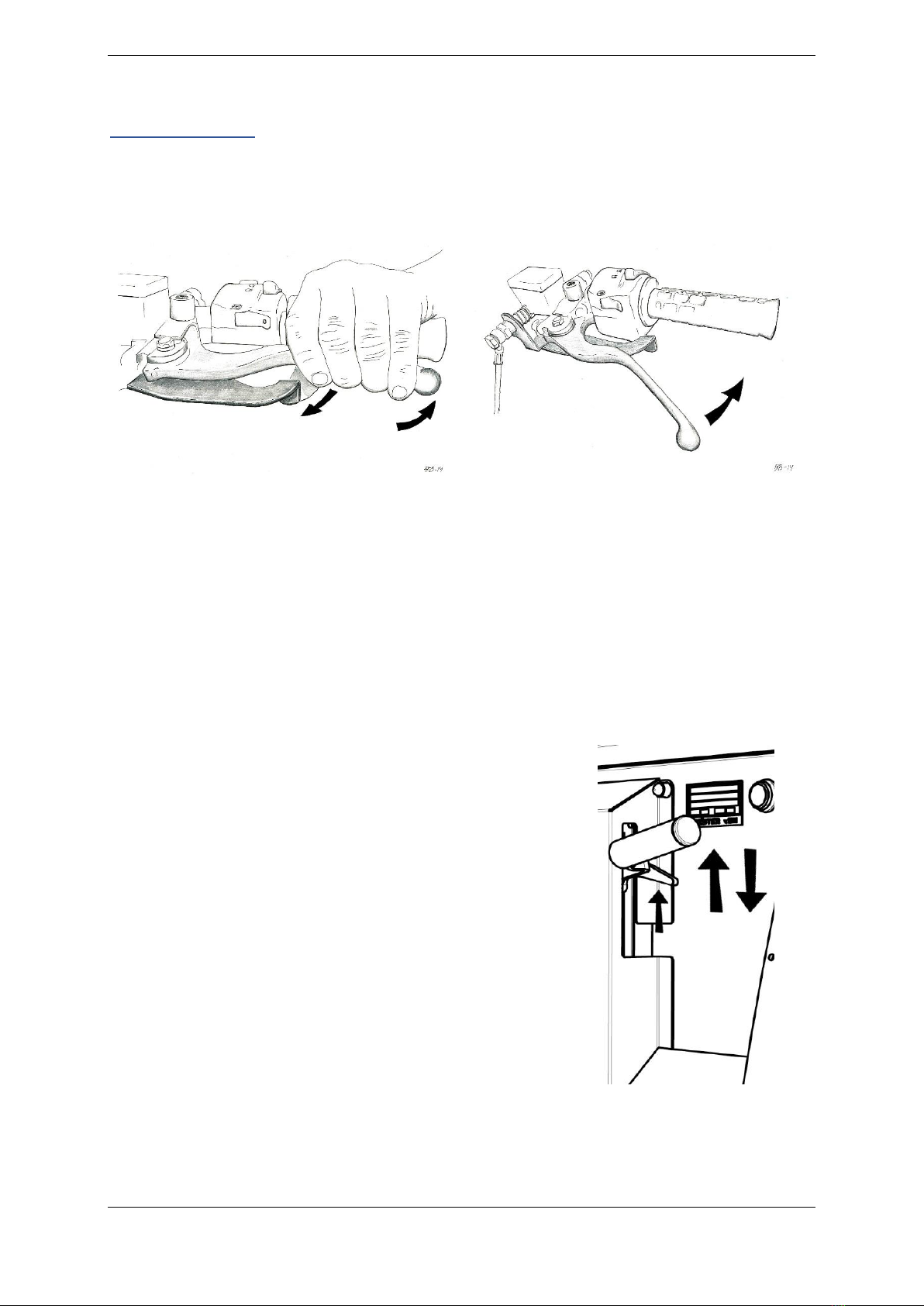
Parking brakes
Parking brake on the handlebar
WARNING: This is only to be used during short stops, where you don’t leave the vehicle.
In order to engage the parking brake, press the brake handle on the left side in at the same time as
the smaller lever below it is pressed away from you. Release the left brake handle before the smaller
lever.
In order to disengage the parking brake, press the brake lever in one more time in the usual way. Do
NOT push the smaller lever.
Note: The smaller lever controls a check-valve that will keep hydraulic rear brake pressurized until you
disengage the parking-brake. If engaged in cold weather, and left on, a rise in temperature will cause the
parking-brake hard to disengage.
Handbrake
If you are going to leave the vehicle, the hand brake should be
engaged. Pull the handbrake-lever upwards, after the vehicle has
come to a complete stop.
Before you start driving, the handbrake is released by pulling the
short lever (the release) upward, and at the same time press the
main lever down.
Make sure that the handbrake is completely disengaged to prevent
unintentional wear, reduced range or overheating the motor.
The hand brake should not be engaged when the vehicle is in
motion.

16
Driving instructions
Starting
Make sure that the load is adequately distributed and secured
Find your correct driving position and check that your field of vision in the mirrors is correct.
Activate the vehicle with the ignition key (right position - clockwise)
Check that the lights are functioning
Choose the correct driving mode
Deactivate the parking brake(s)
Driving forward
Turn the throttle on the right side of the handlebar toward you in order to accelerate
Avoid rapid accelerations because this drains the batteries much faster
Remember to use both the front and rear brakes when braking down in order to achieve the
best possible braking power and in order to reduce the wear on brake discs and pads.
Reverse
Depress and hold in the yellow reverse switch on the left-hand control.
The reversing signal activates.
Adjust the speed with the throttle
Braking and driving on the downhill
The motor functions as generator and helps you maintain a constant speed.
As with all vehicles, excessive use of the ordinary brakes can cause the brakes to be overheated so
that the braking power may disappear. If you are driving in Winter Mode, we recommend that you
pump the brakes and do not use steady braking power. Use both of the brakes in order to avoid
overheating and always use both of the brakes on slippery roads. Take some time to become familiar
with the vehicle’s braking functions in a closed area.
Active regenerative brake
The braking system is equipped with an active regenerative brake that is engaged when the braking
light switch is activated. This applies to both the front and rear brakes. We recommend that this is
used as much as possible, both to reduce wear on brake pads as well as to extend range. In slippery
conditions it is important to note that this effect may cause the rear wheels to slip. In such cases we
recommend pumping the brakes.
Tips for ergonomic and correct driving style
Try to adjust the seat so that you are sitting with your back at an angle of nearly 90 degrees
with the ground when you grip the handlebar.
Adjustment of handlebar angle, may ONLY be performed by competent service personnel.
When the angle of handlebars has been adjusted, the handlebars’ other components must
be correspondingly adjusted. Always check that the brakes work as intended after
adjustment.
Try to set the wheels in motion before you start manoeuvring the vehicle. This greatly
reduces the power required for steering.
If you are going to pass over a curb, maintain a speed of approx. 2-5 km/h, try to approach
the curb at an angle of 45 degrees. This reduces the wear on the suspension.

17
Cargo zones
The vehicle has two loading zones, one in front of the handlebar in the driver’s cab and one in the
rear in the cargo hold. The design and use of these zones varies from user to user, but it is generally
advisable to load weight as low as possible in the vehicle; i.e. that empty postal containers ought to
be placed on top of the cargo hold and full containers at the bottom.
Loading on anterior loading platform
If you use containers in the anterior-loading platform, place them in such a way that the flap on the
back of the platform grips into the container’s lifting handle. Then lower the container and stretch the
elastic cord, if your vehicle is equipped with this, with the steel hook over the upper edge of the
container. This ensures the placement of the container during driving and prevents displacement of the
load during braking or a collision.

18
Do it yourself - maintenance
NOTE: As part of the Warranty Terms, the vehicle must undergo the mandatory semi-annual Periodic Preventive
Maintenance program. It is the Buyers responsibility to book and plan such PPM with a technician authorized by
Paxster AS
Cleaning the vehicle
Keep the vehicle clean by washing it regularly with lukewarm water and car shampoo. If there is a lot of
sand and dust, rinse it off first with water so as to avoid scratches. Then wash with a sponge and running
water until the dirt has come off.
Keep in mind that the surface is composed of plastic so that the use of strong chemicals such as acetone
may make the surface less glossy.
Regular waxing will help protect the surface and make it easier to keep clean. We particularly
recommend waxing the vehicle before winter because road salt and dirt can wear down the surfaces.
NOTE: A high-pressure hose must not be used in the driver compartment, except on the floor, as there is a real
risk that water may penetrate circuit boards. Must be used with caution around the motor and electrical
components.
Filling air in the tires
We recommend using 1.8 to 2.1 bars of pressure in all tires. Make it a habit to check the tire pressure
regularly. Too low pressure will reduce the vehicle’s range considerably. Be aware that the air
pressure can decrease in proportion to the outdoor air temperature.
NOTE: Less tire pressure means softer tires on uneven roads, but please mind the reduced range and harder
steering.
WARNING: When replacing wheels, please note the MAX torque of 90Nm.
Changing fuses
The fuses are located to the left of the steering column.
F1: 30A –12V main fuse
F2: 20A –Window wiper and washer fuse
F3: 10A –Lights and indicators
F4: 10A –Ignition and operation
F5: 20A –Heated windshield and cigarette lighter / heated grips

19
Jacking points
Use the indicated jacking points when the vehicle is to be jacked up.
Changing direction indicator light bulbs
Unscrew the small screw that sits on the rear edge of the light housing.
Remove the lens
To remove the old light bulb: Press the bulb in and turn to the side.
Remove the old bulb.
Do the same thing in order to put the new bulb in.
NOTE: The front direction indicator lights are susceptible to shock. Any damage to these is not covered by
warranty.
Changing headlight bulbs
Turn the handlebars for easier access to the underside of the front wing.
Pull back the rubber collar covering the rear of the light bulb.
Tilt the clip to the side.
Pull the light bulb out.
Reverse the process to replace the light bulb.
WARNING: Only use headlight bulbs of the type HS1 (Max 35 Watt)
NOTE: Your vehicle may be equipped with LED headlights. These do not have replaceable bulbs.

20
FAQ
In this section, information is provided about known events that have been
reported to the manufacturer. Here you will find description of symptoms, and explanation of
possible causes. This will make you better equipped to report any events that may occur to your
servicing partner and to deal with challenges on your own.
Overheating of the drive train
Symptom: The malfunction lamp on the main instrument panel flashes 8 times and it turns off after a
short while. The vehicle has reduced performance. In the event of serious overheating, the vehicle may
come to a sudden stop.
Solution: Turn the ignition off and wait 5 minutes so that the vehicle can cool down.
Known causes:
- The vehicle is exposed to heavy loads, e.g. fully loaded cargo zones and a lot
of hilly terrain.
- Demanding starts on hills with a heavy load.
- The hand brake has not been sufficiently deactivated.
- One or more wheels have low tire pressure.
- Other motor malfunctions
The malfunction does not stop: If the malfunction does not stop, contact your
servicing partner for further diagnosis and repair.
Throttle fault
Symptom: I have turned on the ignition and twisted the throttle, but the vehicle does not respond,
and warning light flashes 6 times.
Solution: Revert throttle to zero position.
Cause: The vehicle is equipped with a safety function that deactivates the
motor if the throttle is not in the 0-position when the ignition is activated. This is to ensure that the
vehicle does not accelerate unintentionally. The same function goes into effect if you twist the throttle
immediately after activating the ignition.
The malfunction does not stop: If the malfunction does not stop, contact your servicing partner for
further diagnosis and repair.
Seat switch
Symptom: I have turned on the ignition, turned the throttle, but the vehicle fails to move and the
warning light flashes twice.
Solution: Make sure you are sitting down on the saddle seat, and that there are no foreign object
hindering the activation of the seat-switch.
Cause: The vehicle is equipped with a safety function that deactivates the motor if the seat is empty
to prevent the vehicle from being operated without a driver on the seat. This is to prevent the
vehicle from accelerating unintentionally. The fault persists: If the fault persists, contact your service
partner for further diagnosis and repair.
Table of contents
Popular Utility Vehicle manuals by other brands


BERG
BERG Hybrid Theme user manual

Textron
Textron Jacobsen Hauler 800 2004 Owner's manual and service guide

Cushman
Cushman Front Line 898810 Operator's manual

Snapper
Snapper GROUNDS CRUISER GC9520KW parts manual

Sodikart
Sodikart GT2 User maintenance guide

Cub Cadet
Cub Cadet Big Country 640 Operator's manual