PCB EX1503M42 User manual
Model EX1503M42
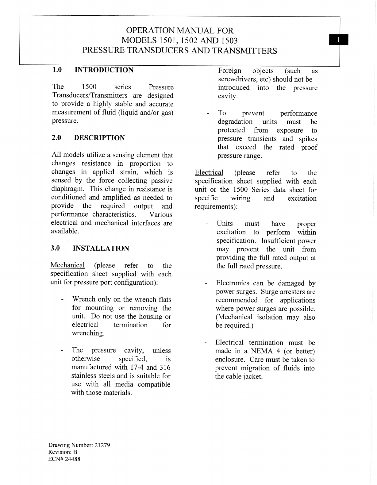
PRESSURE TRANSMITTER (500 PSI) CSA, ATEX, IECEx, ETL approved
Installation and Operating Manual
For assistance with the operation of this product,
contact the PCB Piezotronics, Inc.
Toll-free: 716-684-0001
24-hour SensorLine: 716-684-0001
Fax: 716-684-0987
E-mail: [email protected]
Web: www.pcb.com
Manual 21354 Rev E
ECN 50523
Repair and Maintenance
PCB guarantees Total Customer Satisfaction through its
“Lifetime Warranty Plus” on all Platinum Stock Products
sold by PCB and through its limited warranties on all other
PCB Stock, Standard and Special products. Due to the
sophisticated nature of our sensors and associated
instrumentation, field servicing and repair is not
recommended and, if attempted, will void the factory
warranty.
Beyond routine calibration and battery replacements
where applicable, our products require no user
maintenance. Clean electrical connectors, housings, and
mounting surfaces with solutions and techniques that will
not harm the material of construction. Observe caution
when using liquids near devices that are not hermetically
sealed. Such devices should only be wiped with a
dampened cloth—never saturated or submerged.
In the event that equipment becomes damaged or ceases
to operate, our Application Engineers are here to support
your troubleshooting efforts 24 hours a day, 7 days a
week. Call or email with model and serial number as well
as a brief description of the problem.
Calibration
Routine calibration of sensors and associated
instrumentation is necessary to maintain measurement
accuracy. We recommend calibrating on an annual basis,
after exposure to any extreme environmental influence,
or prior to any critical test.
PCB Piezotronics is an ISO-9001 certified company whose
calibration services are accredited by A2LA to ISO/IEC
17025, with full traceability to SI through N.I.S.T. In
addition to our standard calibration services, we also offer
specialized tests, including: sensitivity at elevated or
cryogenic temperatures, phase response, extended high
or low frequency response, extended range, leak testing,
hydrostatic pressure testing, and others. For more
information, contact your local PCB Piezotronics
distributor, sales representative, or factory customer
service representative.
Returning Equipment
If factory repair is required, our representatives will
provide you with a Return Material Authorization (RMA)
number, which we use to reference any information you
have already provided and expedite the repair process.
This number should be clearly marked on the outside of
all returned package(s) and on any packing list(s)
accompanying the shipment.
Contact Information
PCB Piezotronics, Inc.
3425 Walden Ave.
Depew, NY14043 USA
Toll-free: (800) 828-8840
24-hour SensorLine: (716) 684-0001
Repair inquiries: rma@pcb.com
For a complete list of distributors, global offices and sales
representatives, visit our website, www.pcb.com.
Safety Considerations
This product is intended for use by qualified personnel
who recognize shock hazards and are familiar with the
precautions required to avoid injury. While our equipment
is designed with user safety in mind, the protection
provided by the equipment may be impaired if equipment
is used in a manner not specified by this manual.
Discontinue use and contact our 24-Hour Sensorline if:
Assistance is needed to safely operate equipment
Damage is visible or suspected
Equipment fails or malfunctions
For complete equipment ratings, refer to the enclosed
specification sheet for your product.
Definition of Terms and Symbols
The following symbols may be used in this manual:
DANGER
Indicates an immediate hazardous
situation, which, if not avoided, may
result in death or serious injury.
Manual 21354 Rev E
ECN 50523
CAUTION
Refers to hazards that could damage
the instrument.
NOTE
Indicates tips, recommendations and
important information. The notes
simplify processes and contain
additional information on particular
operating steps.
The following symbols may be found on the equipment
described in this manual:
This symbol on the unit indicates that
high voltage may be present. Use
standard safety precautions to avoid
personal contact with this voltage.
This symbol on the unit indicates that
the user should refer to the operating
instructions located in the manual.
This symbol indicates safety, earth
ground.
Manual 21354 Rev E
ECN 50523
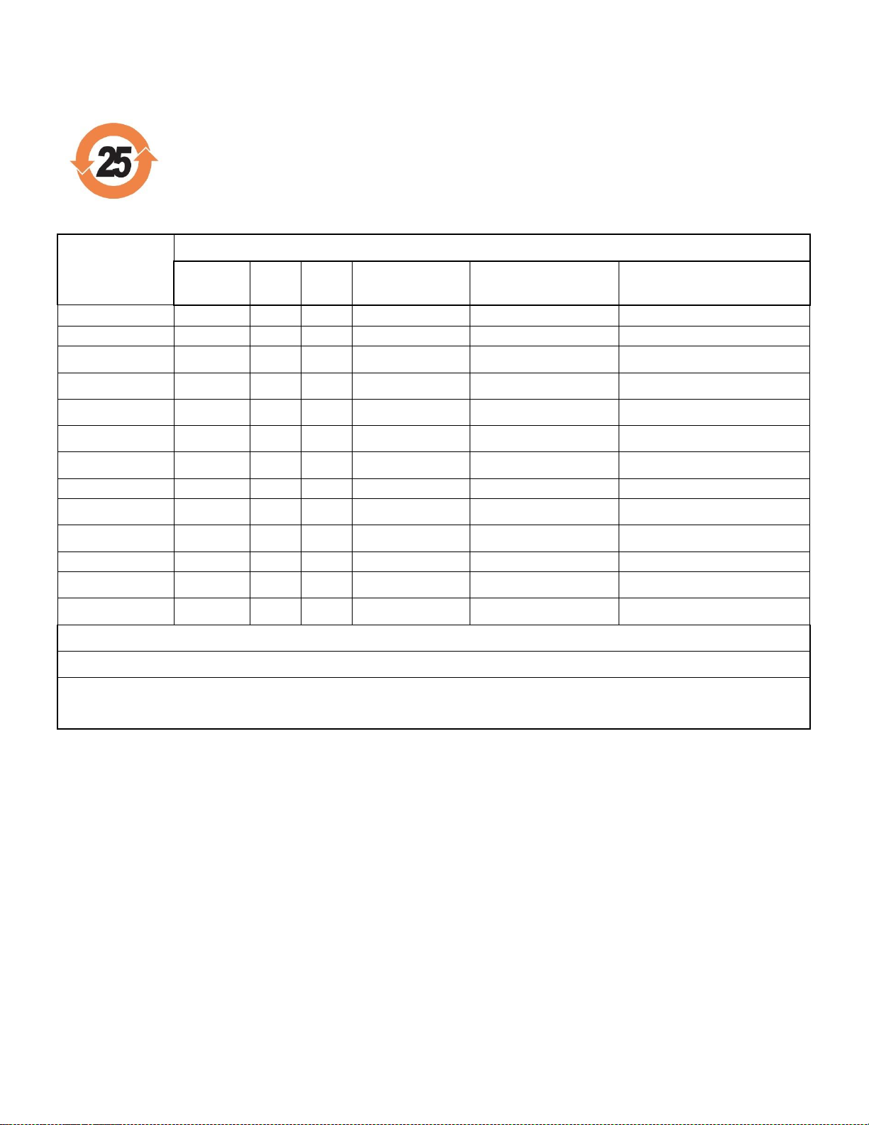
PCB工业监视和测量设备 - 中国RoHS2公布表
PCB Industrial Monitoring and Measuring Equipment - China RoHS 2 Disclosure Table
部件名称
有害物质
铅(Pb)
汞
(Hg)
镉
(Cd)
六价铬(Cr(VI))
多溴联苯 (PBB)
多溴二苯醚(PBDE)
住房
O
O
O
O
O
O
PCB板
X
O
O
O
O
O
电气连接器
O
O
O
O
O
O
压电晶体
X
O
O
O
O
O
环氧
O
O
O
O
O
O
铁氟龙
O
O
O
O
O
O
电子
O
O
O
O
O
O
厚膜基板
O
O
X
O
O
O
电线
O
O
O
O
O
O
电缆
X
O
O
O
O
O
塑料
O
O
O
O
O
O
焊接
X
O
O
O
O
O
铜合金/黄铜
X
O
O
O
O
O
本表格依据 SJ/T 11364 的规定编制。
O:表示该有害物质在该部件所有均质材料中的含量均在 GB/T 26572 规定的限量要求以下。
X:表示该有害物质至少在该部件的某一均质材料中的含量超出 GB/T 26572 规定的限量要求。
铅是欧洲RoHS指令2011/65/ EU附件三和附件四目前由于允许的豁免。
CHINA RoHS COMPLIANCE

Manual 21354 Rev E
ECN 50523
Component Name
Hazardous Substances
Lead (Pb)
Mercury (Hg)
Cadmium (Cd)
Chromium VI
Compounds
(Cr(VI))
Polybrominated
Biphenyls (PBB)
Polybrominated
Diphenyl Ethers
(PBDE)
Housing
O
O
O
O
O
O
PCB Board
X
O
O
O
O
O
Electrical Connectors
O
O
O
O
O
O
Piezoelectric Crystals
X
O
O
O
O
O
Epoxy
O
O
O
O
O
O
Teflon
O
O
O
O
O
O
Electronics
O
O
O
O
O
O
Thick Film Substrate
O
O
X
O
O
O
Wires
O
O
O
O
O
O
Cables
X
O
O
O
O
O
Plastic
O
O
O
O
O
O
Solder
X
O
O
O
O
O
Copper Alloy/Brass
X
O
O
O
O
O
This table is prepared in accordance with the provisions of SJ/T 11364.
O: Indicates that said hazardous substance contained in all of the homogeneous materials for this part is below the limit
requirement of GB/T 26572.
X: Indicates that said hazardous substance contained in at least one of the homogeneous materials for this part is above the limit
requirement of GB/T 26572.
Lead is present due to allowed exemption in Annex III or Annex IV of the European RoHS Directive 2011/65/EU.


Model Number
EX1503M 42 PRESSURE TRANSMITTER Revision: NR
ECN #: 53014
Performance ENGLISH SI
Measurement Range 500 psig 3,447 kPa
Output 4-20 mA 4-20 mA [1]
Accuracy ≤ .35 % FS ≤ .35 % FS [2]
Linearity ≤ .25 % FS ≤ .25 % FS
Hysteresis ≤ 0.2 % FS ≤ 0.2 % FS
Repeatability ≤ 0.1 % FS ≤ 0.1 % FS [3]
Zero Output Tolerance ± 0.3 % FS ± 0.3 % FS [1]
Span Tolerance ± 0.3 % FS ± 0.3 % FS [1]
Resolution ≤ 150 mpsi ≤ 1.03 kPa [3]
Resonant Frequency > 2 kHz > 2 kHz
Environ mental
Proof Pressure 2 x FS 2 x FS
Burst Pressure 3 x FS 3 x FS
Temperature Range(Operating) -65 to +300 °F -55 to +149 °C
Temperature Range(Compensated) -40 to +250 °F -40 to +121 °C
Thermal Error(Span) ± 2 % FS ± 2 % FS [4]
Thermal Error(Zero Shift) ± 2 % FS ± 2 % FS [4]
Acceleration Sensitivity(Maximum)(any
direction)
≤ 0.005 %FS/g ≤ 0.05 % FS / (m/s²)
Maximum Shock 1,000 g pk 9,800 m/s² pk
Vibration Survivability 50 g pk 495 m/s² pk
Hazardous Area Approval See Manual See Manual
Electrical
Supply Voltage 15 to 28 VDC 15 to 28 VDC
Electrical Isolation(at 50 VDC) > 100 MOhm > 100 MOhm
Physical
Sensing Element Foil Strain Gage (Full Bridge) Foil Strain Gage (Full Bridge)
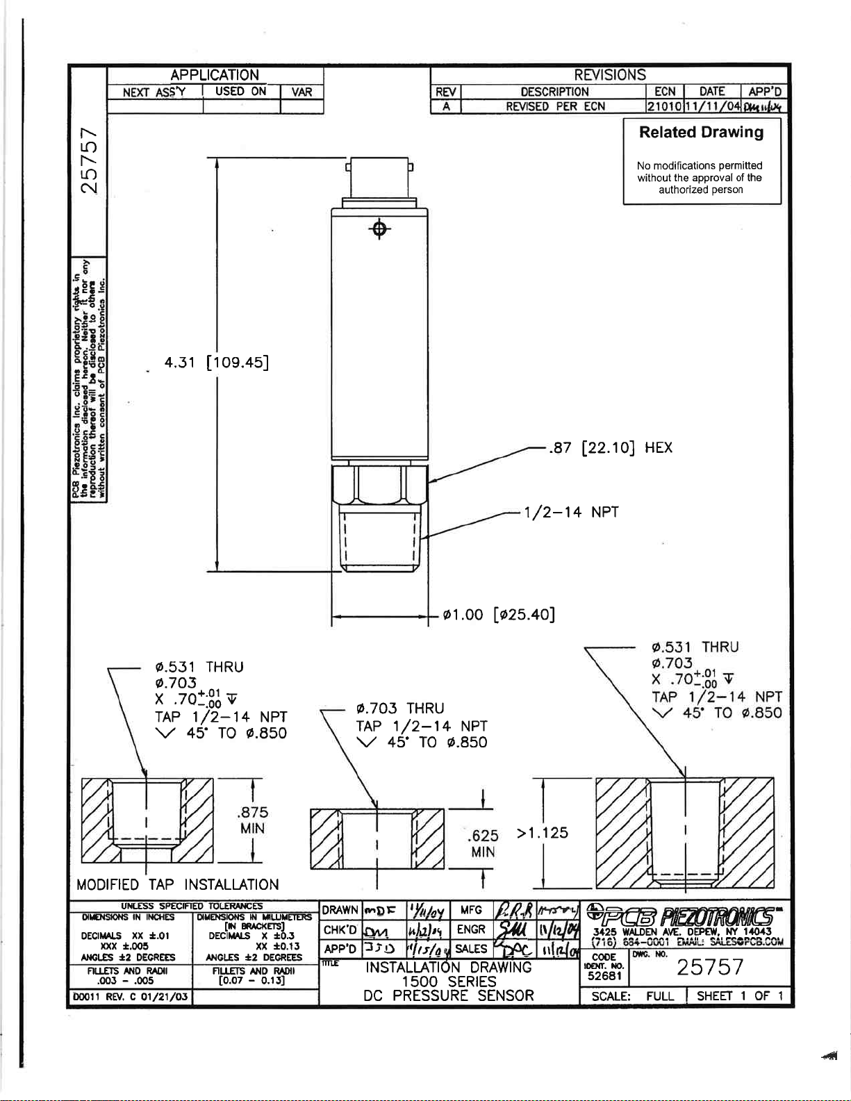
Pressure Port 1/2-14 NPT 1/2-14 NPT
Thread External External
Dead Volume 0.3 in³ 4,900 mm³ [3]
Wetted Parts Material 17-4 PH Stainless Steel 17-4 PH Stainless Steel
Housing Material 304/304L Stainless Steel 304/304L Stainless Steel
Electrical Connector 6-Pin Bayonet Jack 6-Pin Bayonet Jack
Electrical Connections(Pin A) Pos (+) Power/Signal Pos (+) Power/Signal
Electrical Connections(Pin D) Neg (-) Power/Signal Neg (-) Power/Signal
Weight(without cable) 5.36 oz 152 gm
[5]
[6]
All specifications are at room temperature unless otherwise specified.
In the interest of constant product improvement, we reserve the right to change specifications without notice.
ICP® is a registered trademark of PCB Piezotronics, Inc.
OPTION AL VERSION S
Optional versions have identical specifications and accessories as listed for the standard model except
where noted below. More than one option may be used.
NOTES:
[1]Adjustable.
[2]Combined least squares linearity, hysteresis and repeatability.
[3]Typical.
[4]Over compensated temperature range.
[5]See PCB Declaration of Conformance PS231 for details
[6]See Model's “Instructions For Use” (IFU) for North American Conformity and Certification
Statements.
Date: 07/12/2022 Date: 07/12/2022 Date: 07/12/2022 Date: 07/12/2022 76573
Entered: ND Engineer: RPF Sales: DPC Approved: RPF Spec Number:
Phone: 716-684-0001
Fax: 716-684-0987
E-Mail: info@pcb.com
3425 Walden Avenue, Depew, NY 14043
1
1
2
2
3
3
4
4
A A
B B
PCB Piezotronics Inc. claims proprietary rights in
the information disclosed hereon. Neither it nor any
reproduction thereof will be disclosed to others
without the written consent of PCB Piezotronics Inc.
69269
CODE
IDENT. NO.
52681
DWG. NO.
SCALE: SHEET
DRAWN CHECKED ENGINEER
TITLE
UNLESS OTHERWISE SPECIFIED
DIMENSIONS ARE IN INCHES
DECIMALS X ` .05
XX ` .01
XXX ` .005
ANGLES ± 2 DEGREES
FILLETS AND RADII .003 - .005
HEX DIMENSIONS ARE:
≤ .5 + .000 / - .003
> .5 + .000 / - .005
REMOVE ALL BURRS
SHARP = R.000 - R.003
INTERNAL THREAD DEPTH MIN.
3425 WALDEN AVE. DEPEW, NY 14043
(716) 684-0002 E-MAIL: [email protected]
XXXX ` .0005
APPROVAL
INTERCONNECTION 69269
1 OF 2NONE
JJF 3/25/22 JJF 3/25/22 RF 3/25/22
REVISIONS
REV DESCRIPTION DIN
NR RELEASED TO DRAFTING 52686
CAUTION
ELECTROSTATIC
DISCHARGE SENSITIVE
SCHEDULE DRAWING
NO MODIFICATIONS PERMITTED
WITHOUT REFERENCE TO THE
NOTIFIED BODY

1
1
2
2
3
3
4
4
A A
B B
PCB Piezotronics Inc. claims proprietary rights in
the information disclosed hereon. Neither it nor any
reproduction thereof will be disclosed to others
without the written consent of PCB Piezotronics Inc.
69269
REVISIONS
REV DESCRIPTION DIN
- SEE SHEET 1 -
CODE
IDENT. NO.
52681
DWG. NO.
SCALE: SHEET
DRAWN CHECKED ENGINEER
TITLE
UNLESS OTHERWISE SPECIFIED
DIMENSIONS ARE IN INCHES
DECIMALS X ` .05
XX ` .01
XXX ` .005
ANGLES ± 2 DEGREES
FILLETS AND RADII .003 - .005
HEX DIMENSIONS ARE:
≤ .5 + .000 / - .003
> .5 + .000 / - .005
REMOVE ALL BURRS
SHARP = R.000 - R.003
INTERNAL THREAD DEPTH MIN.
3425 WALDEN AVE. DEPEW, NY 14043
(716) 684-0002 E-MAIL: [email protected]
XXXX ` .0005
APPROVAL
INTERCONNECTION 69269
2 OF 2NONE
JJF 3/25/22 JJF 3/25/22 RF 3/25/22
CAUTION
ELECTROSTATIC
DISCHARGE SENSITIVE
SCHEDULE DRAWING
NO MODIFICATIONS PERMITTED
WITHOUT REFERENCE TO THE
NOTIFIED BODY
IECEx Certificate
of Conformity
INTERNATIONAL ELECTROTECHNICAL COMMISSION
IEC Certification System for Explosive Atmospheres
for rules and details of the IECEx Scheme visit www.iecex.com
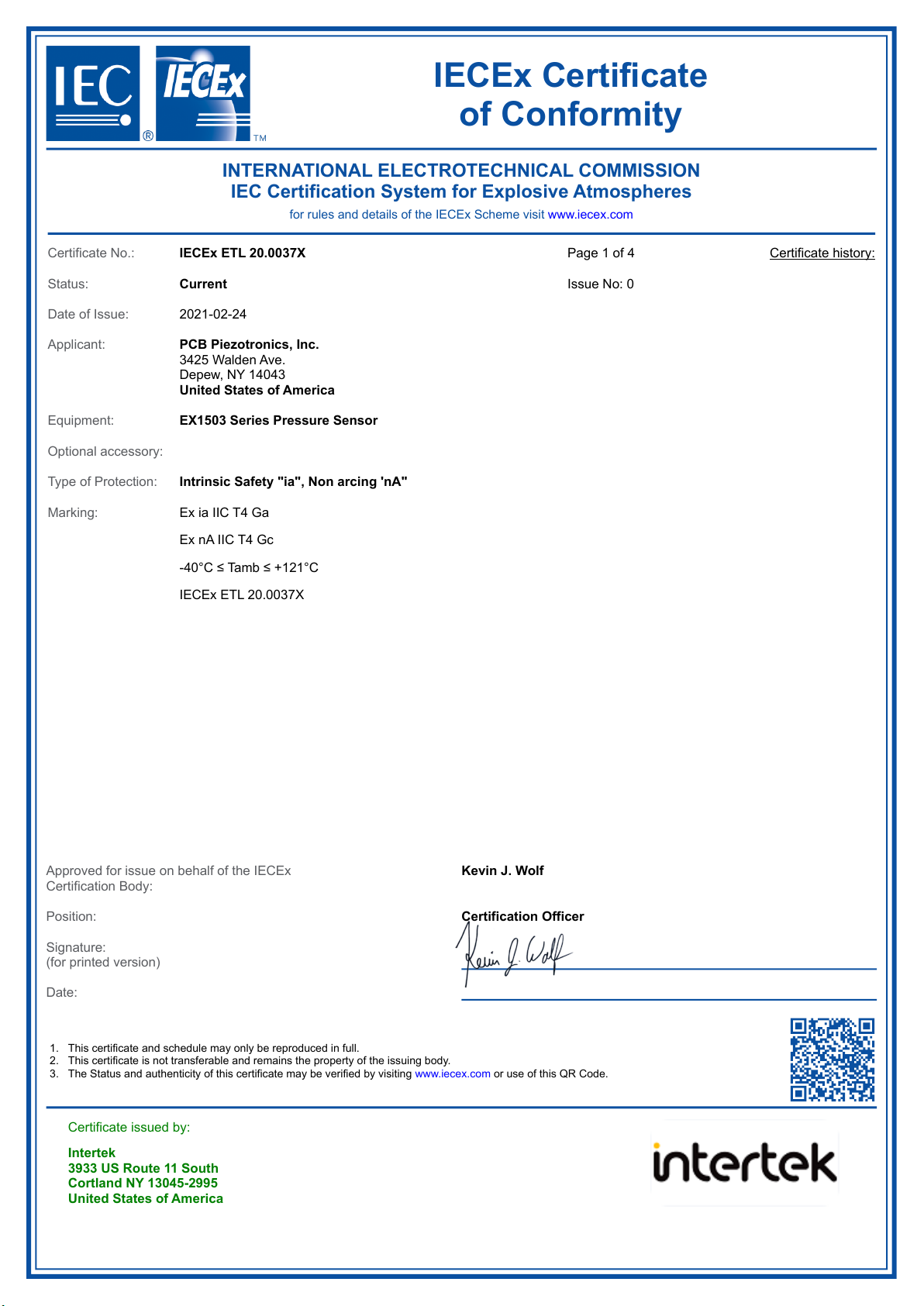
Certificate No.: IECEx ETL 20.0037X
Status: Current
Date of Issue: 2021-02-24
Applicant: PCB Piezotronics, Inc.
3425 Walden Ave.
Depew, NY 14043
United States of America
Equipment: EX1503 Series Pressure Sensor
Optional accessory:
Type of Protection: Intrinsic Safety "ia", Non arcing 'nA"
Marking:
Page 1 of 4
Issue No: 0
Certificate history:
Ex ia IIC T4 Ga
Ex nA IIC T4 Gc
-40°C ≤ Tamb ≤ +121°C
IECEx ETL 20.0037X
1.
2.
3.
Approved for issue on behalf of the IECEx
Certification Body:
Position:
Signature:
(for printed version)
Date:
This certificate and schedule may only be reproduced in full.
This certificate is not transferable and remains the property of the issuing body.
The Status and authenticity of this certificate may be verified by visiting www.iecex.com or use of this QR Code.
Certificate issued by:
Intertek
3933 US Route 11 South
Cortland NY 13045-2995
United States of America
Kevin J. Wolf
Certification Officer
2021-02-24

IECEx Certificate
of Conformity
Certificate No.: IECEx ETL 20.0037X
Date of issue: 2021-02-24
Page 2 of 4
Issue No: 0
Manufacturer: PCB Piezotronics, Inc.
3425 Walden Ave.
Depew, NY 14043
United States of America
Additional
manufacturing
locations:
This certificate is issued as verification that a sample(s), representative of production, was assessed and tested and found to comply with the
IEC Standard list below and that the manufacturer's quality system, relating to the Ex products covered by this certificate, was assessed and
found to comply with the IECEx Quality system requirements.This certificate is granted subject to the conditions as set out in IECEx Scheme
Rules, IECEx 02 and Operational Documents as amended
STANDARDS :
The equipment and any acceptable variations to it specified in the schedule of this certificate and the identified documents, was found
to comply with the following standards
IEC 60079-0:2017
Edition:7.0
Explosive atmospheres - Part 0: Equipment - General requirements
IEC 60079-11:2011
Edition:6.0
Explosive atmospheres - Part 11: Equipment protection by intrinsic safety "i"
IEC 60079-15:2010
Edition:4
Explosive atmospheres - Part 15: Equipment protection by type of protection "n"
This Certificate does not indicate compliance with safety and performance requirements
other than those expressly included in the Standards listed above.
TEST & ASSESSMENT REPORTS:
A sample(s) of the equipment listed has successfully met the examination and test requirements as recorded in:
Test Reports:
Quality Assessment Report:
US/ETL/ExTR20.0043/00 US/ETL/ExTR20.0044/00
NL/DEK/QAR14.0004/04
IECEx Certificate
of Conformity
Certificate No.: IECEx ETL 20.0037X
Date of issue: 2021-02-24
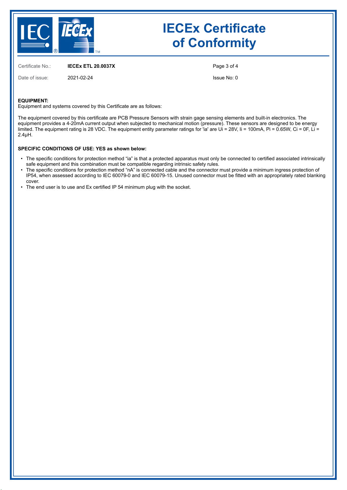
Page 3 of 4
Issue No: 0
EQUIPMENT:
Equipment and systems covered by this Certificate are as follows:
SPECIFIC CONDITIONS OF USE: YES as shown below:
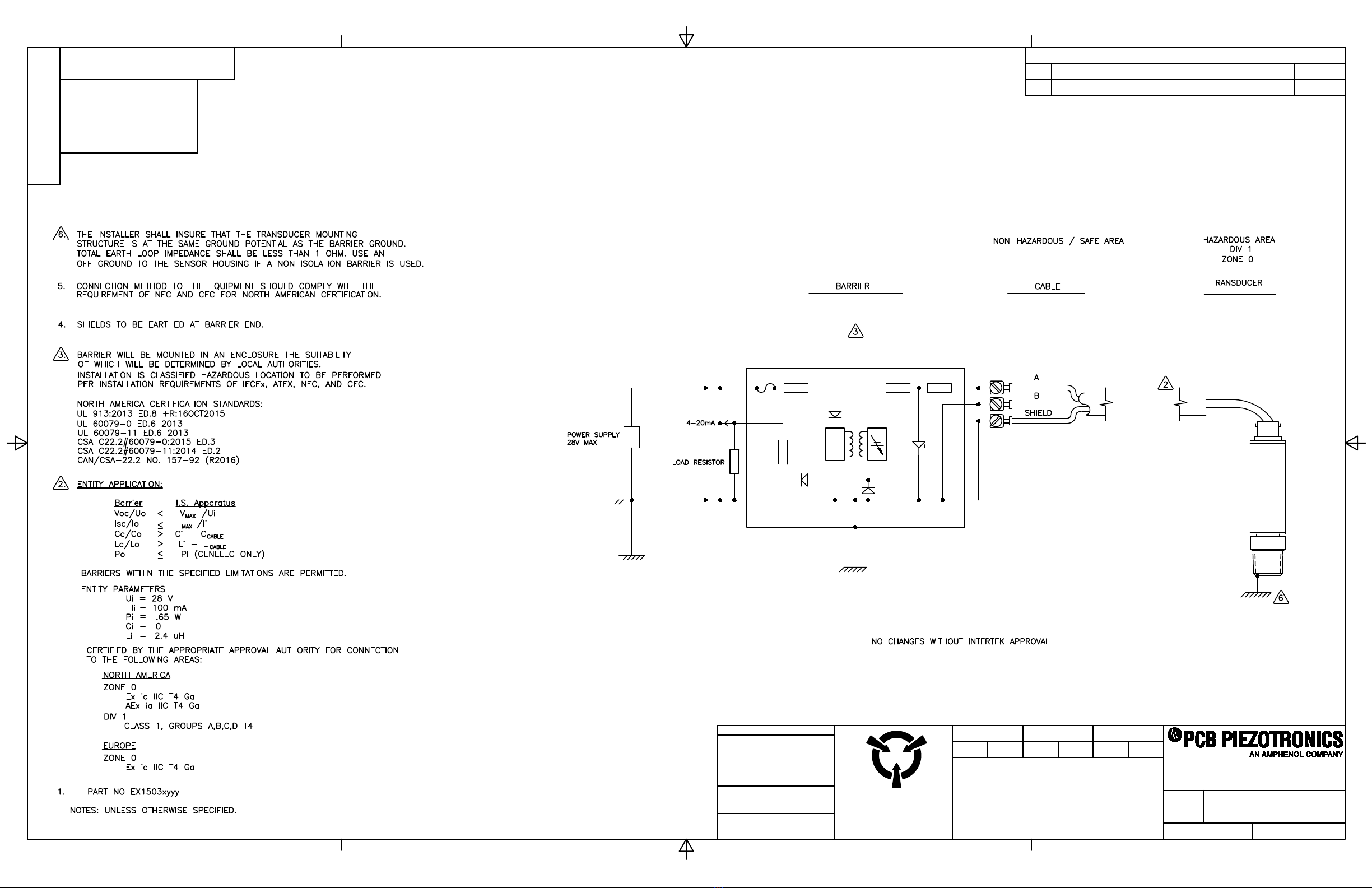
The equipment covered by this certificate are PCB Pressure Sensors with strain gage sensing elements and built-in electronics. The
equipment provides a 4-20mA current output when subjected to mechanical motion (pressure). These sensors are designed to be energy
limited. The equipment rating is 28 VDC. The equipment entity parameter ratings for 'ia' are Ui = 28V, Ii = 100mA, Pi = 0.65W, Ci = 0F, Li =
2.4μH.
•
•
•
The specific conditions for protection method “ia” is that a protected apparatus must only be connected to certified associated intrinsically
safe equipment and this combination must be compatible regarding intrinsic safety rules.
The specific conditions for protection method “nA” is connected cable and the connector must provide a minimum ingress protection of
IP54, when assessed according to IEC 60079-0 and IEC 60079-15. Unused connector must be fitted with an appropriately rated blanking
cover.
The end user is to use and Ex certified IP 54 minimum plug with the socket.

IECEx Certificate
of Conformity
Certificate No.: IECEx ETL 20.0037X
Date of issue: 2021-02-24
Page 4 of 4
Issue No: 0
Equipment (continued):
Annex:
103974085CRT-001 - Annex for IECEx Certificate.pdf
EX1503xyyy Series Pressure Sensors where:
x = A through Z Family Code
yyy = 01 through 999 indicating variations in sensitivity, mounting thread or adaptor.
Annex to IECEx Certificate of Conformity
Certificate No:
IECEx ETL 20.0037X
Issue No. 0
Annex No. 1
Certificate issued by:
Intertek Testing Services NA
3933 Us Route 11, Cortland, NY
13045 USA
Page 1 of 1
SFT-IECEx-OP-19f (26 October 2018)
Technical Documents ‘nA’
Title:
Drawing No.:
Rev. Level:
Date:
IECEx Technical File Non-Arcing (Sheets: 2)
69279
NR
April 9, 2018
Descriptive Notice For The Certification Of PCB
Pressure Sensors
69277
NR
April 9, 2018
Approval Board Assembly
74229
NR
-
Etching Drawing
69272
NR
-
Approval Schematic & BOM (Sheets: 2)
69297
NR
1/4/2021
Approval Assembly Model EX1503 Series
74226
NR
1/4/2021
Approval Interconnection (Sheets: 2)
69269
NR
1/4/2021
Instructions For Use –EX1503 Series Pressure
Sensors (Sheets: 2)
69307
NR
-
Technical Documents ‘ia’
Title:
Drawing No.:
Rev. Level:
Date:
IECEx Technical File
Intrinsic Safety (Sheets: 2)
69278
NR
April 9, 2018
Descriptive Notice For The Certification Of PCB
Pressure Sensors
69276
NR
April 9, 2018
Approval Board Assembly
74229
NR
-
Etching Drawing
69272
NR
1/4/2021
Approval Schematic & BOM (Sheets: 2)
69297
NR
1/4/2021
Approval Assembly Model EX1503 Series
74226
NR
1/4/2021
Approval Interconnection (Sheets: 2)
69269
NR
1/4/2021
Instructions For Use –EX1503 Series Pressure
Sensors (Sheets: 2)
69307
NR
-
Required Manufacturer Routine Testing
Test
Title/Description of Test
Standard and Clause
1
Dielectric Strength Test
•A routine dielectric strength test shall be carried out in accordance with
Clause 23.2.1. Alternatively, a test shall be carried out at 1.2 times the
test voltage but maintained for at least 100ms.
IEC 60079-15 Clause 23.2.1

TYPE-EXAMINATION CERTIFICATE
This Certificate is for the exclusive useofIntertek's client and isprovidedpursuant tothe agreement between Intertekand its Client. Intertek's
responsibilityand liability are limitedto the terms and conditions of the agreement. Intertek assumes no liability to any party, other than to the Client in
accordance with the agreement, for any loss, expense or damage occasioned by the use of this Certificate.Only the Client is authorized to permit copying
or distribution of this Certificate and then only in itsentirety. Anyuse of the Intertek name or one of its marks forthe sale or advertisement of the tested
material, product or service must first be approved in writing by Intertek.
Intertek Italia S.p.A. Via Miglioli, 2/A - 20063 Cernuscosul Naviglio, Milano - Italy
LFT-EMEA-IT-ATEX-OP -23p (29 August2019) Page 1 of 3
Certificate issue date
Todd L. Relyea
Certification Officer
Intertek Italia S.p.A.
31 March 2021
1. Type-examination Certificate (Module A)
2. Equipment or Protective System intended for use in potentially explosive atmospheres (Directive
2014/34/EU)
3. Type examination certificate Nr
ITS-I21ATEX28703X R.0
4. Product:
EX1503 Series Pressure Sensors
5. Manufacturer:
PCB Piezotronics, Inc.
Applicant:
PCB Piezotronics, Inc.
6. Address:
3425 Walden Ave
Depew, NY 14043
USA
Address:
3425 Walden Ave
Depew, NY 14043
USA
7. This product and any acceptable variation thereto are specified in the schedule to this certificate and therein referred to.
8. INTERTEK ITALIA S.p.A., certifies that the equipment or protective system has been found to comply with the essential
Health and Safety Requirements relating to the design and construction of equipment and protective system intended for
use in potentially explosive atmosphere, given in Annex II of the Directive.
The examination and tests results are recorded in confidential technical evaluation Intertek Report Nr. 103974085CRT-
004b.
9. Compliance with the Essential Health and Safety Requirements has been assured by compliance with EN IEC 60079-0:2018
and EN 60079-15:2010…except in respect of those requirements referred to at item 16 of the Schedule
10. If the sign X is placed after the certificate number, it indicates that the product is subject to Special Conditions for Safe
Use specified in the schedule to this certificate.
11. This Type Examination Certificate relates only to the design and construction of the specified product. Further
requirements of the Directive apply to the manufacturing process and supply of this product. These are not covered by
this certificate.
12. The marking of the product shall include the following:
II 3 G
Ex nA IIC T4 Gc
Tamb: -40°C to +121°C

SCHEDULE
TYPE EXAMINATION CERTIFICATE NUMBER: ITS-I21ATEX28703X R.0
LFT-EMEA-IT-ATEX-OP -23p (29 August2019) Page 2 of 3
13. DESCRIPTION OF THE EQUIPMENT OR PROTECTIVE SYSTEM
The equipment covered by this certificate are PCB Pressure Sensors withstrain gage sensingelements and built-
in electronics. The equipment provides a 4-20mA current output when subjected to mechanicalmotion
(pressure). Thesesensorsare designed tobe energy limited. The equipment ratings are Ui = 28V, Ii = 100mA, Pi
= 0.65W, Ci = 0F, Li = 2.4μH.
EX1503xyyy Series Pressure Sensors where:
x = A through Z Family Code
yyy = 01 through 999 indicating variations in sensitivity, mounting thread or adaptor.
14. DRAWINGS AND DOCUMENTS
TITLE
DOCUMENT Nr
LEVEL
DATE
ATEX Technical File Non-Arcing (Sheets: 2)
34627
NR
April 9, 2018
Descriptive Notice For The Certification Of PCB Pressure
Sensors
34628
NR
April 9, 2018
ApprovalBoard Assembly
74229
NR
-
Etching Drawing
69272
NR
-
ApprovalSchematic & BOM (Sheets: 2)
69297
NR
1/4/2021
ApprovalAssembly ModelEX1503 Series
74226
NR
1/4/2021
ApprovalInterconnection (Sheets: 2)
69269
NR
1/4/2021
Instructions For Use –EX1503 Series Pressure Sensors
(Sheets: 2)
69307
NR
-
Copies of the above listed documents are kept at Intertek Italia S.p.A. archive.
15. SPECIAL CONDITIONS FOR SAFE USE
The apparatus must be onlyconnected to an equipment whose electricalparameters are compatible with the
electrical parameters. The apparatus shall be connected according to drawing 69269 (page 2/2). The connected
cable and the connectormust provide a minimum ingress protection of IP54, when assessed according to EN
60079-0 and EN60079-15. Unused connectormust be fitted with an appropriately rated blanking cover.
16. ESSENTIAL HEALTH AND SAFETY REQUIREMENTS
The relevant essentialHealth and Safety Requirements have been identified and assessed in Intertek Report Nr.
103974085CRT-004b Revision 0 dated 103974085CRT-004b

SCHEDULE
TYPE EXAMINATION CERTIFICATE NUMBER: ITS-I21ATEX28703X R.0
LFT-EMEA-IT-ATEX-OP -23p (29 August2019) Page 3 of 3
17. ROUTINE (FACTORY) TESTS
Dielectric Strength Test
•A routine dielectric strength testshall be carried out in accordance with Clause 23.2.1. Alternatively, a
test shall be carried out at 1.2 times the test voltage but maintained for at least100ms.
Table of contents
Popular Transmitter manuals by other brands

NIVELCO
NIVELCO AnaCONT LE-100 Installation and programming manual

BWI Eagle
BWI Eagle AIR-EAGLE SR PLUS manual

Williams Sound
Williams Sound PPA T46 Instructions for use and care

Dwyer Instruments
Dwyer Instruments Magnesense MS Series Installation and operating instructions

SY Electronics
SY Electronics MFT-31C user manual

Crestron
Crestron DigitalMedia DM-TX-300N Operation guide

JUMO
JUMO dTRANS p02 DELTA operating manual

Lectrosonics
Lectrosonics UM400AV instruction manual

Emerson
Emerson Rosemount MultiVariable 3051SMV quick start guide

Pyle view
Pyle view PLVWGM3 supplementary guide

EUTECH INSTRUMENTS
EUTECH INSTRUMENTS ALPHA PH 200 - REV 4 instruction manual

KMC Controls
KMC Controls THE-1102 installation guide


