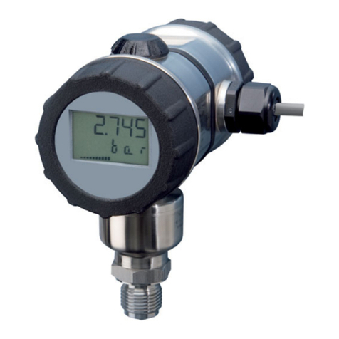
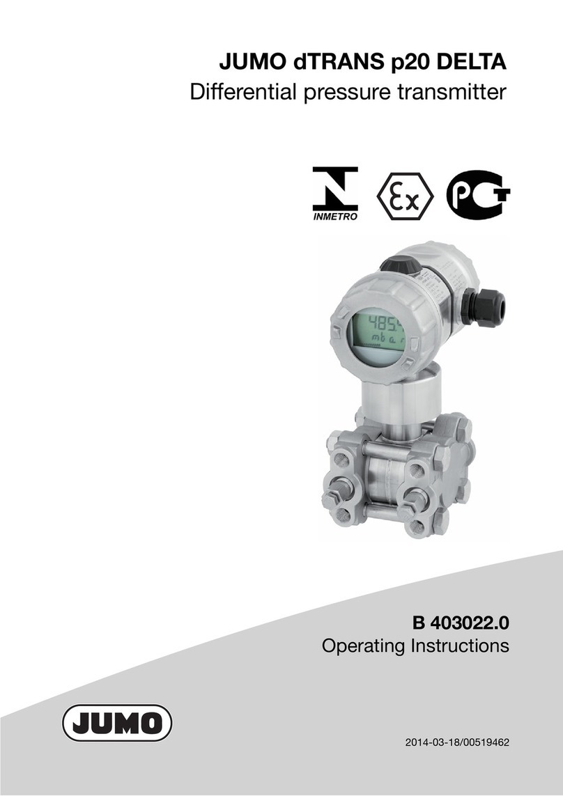
JUMO dTRANS p02 DELTA User manual

JUMO dTRANS p02 DELTA
Pressure Transmitter
B 404382.0
Operating Manual
V2.00/EN/00381278


Contents
1 General information ............................................................. 5
1.1 Scope of application ............................................................................ 5
2 Safety information ............................................................... 7
2.1 Warning signs ...................................................................................... 7
2.2 Reference signs ................................................................................... 7
3 Delivery package ................................................................. 9
4 Instrument identification ................................................... 11
4.1 Nameplate ......................................................................................... 11
4.2 Order details ...................................................................................... 12
4.3 Accessories ....................................................................................... 13
4.4 Dimensions/details ............................................................................ 14
5 Technical data .................................................................... 15
5.1 For pressure transmitters without intrinsic safety ............................. 15
6 Mounting ............................................................................. 17
6.1 General .............................................................................................. 17
6.2 Prior to mounting ............................................................................... 17
6.3 Mounting by the valve block ............................................................. 18
6.4 Mounting by the angle bracket for fixing to a wall or pipe ................ 18
6.5 Pressure connection .......................................................................... 19
6.6 Use inside the Ex area ....................................................................... 19
7 Installation .......................................................................... 21
7.1 Electrical connection ......................................................................... 21
7.2 Testing the output signal ................................................................... 23
7.3 Connection of a HART®modem ....................................................... 24
7.4 Testing the HART®communication .................................................. 25
7.5 Electrical connection in the hazardous (Ex) area ............................... 26
8 Commissioning .................................................................. 29
8.1 Characteristic .................................................................................... 29
8.2 Self-test ............................................................................................. 30
8.3 Warnings ............................................................................................ 31


Contents
8.4 Measuring the differential pressure ................................................... 32
9 Adjustment options ........................................................... 37
9.1 The level concept .............................................................................. 37
9.2 Sequence for keypad operation ........................................................ 38
9.3 Display level ....................................................................................... 39
9.4 Parameter level .................................................................................. 40
9.5 Detailed explanations ........................................................................ 43
10 Opening the instrument .................................................... 47
10.1 Unscrewing the bezel ring or housing cover ..................................... 47
11 Rotating the instrument .................................................... 49
11.1 Rotating the LCD display ................................................................... 49
11.2 Rotating the housing ......................................................................... 49
12 Maintenance ....................................................................... 51
12.1 Trouble-shooting ............................................................................... 51
13 Appendix ............................................................................. 53
13.1 Settings .............................................................................................. 53
14 Declaration of conformity ................................................. 55
15 Type Examination Certificate ........................................... 59
16 China RoHS ........................................................................ 63

5
1 General information
1.1 Scope of application
General information
The type dTRANS p02 DELTA pressure transmitter measures the differential pressure of cor-
rosive and non-corrosive gases, vapors and liquids. The pressure transmitter utilizes the
piezo-resistive measuring principle. The output signal is a DC current which is linearly pro-
portional to the input pressure. For flow measurements, the output signal can be set up to be
proportional to the square root of the input pressure.
Version with Ex protection
The JUMO dTRANS p02 DELTA pressure transmitter in intrinsically-safe version marked
II 1/2 G Ex ia IIC T6 Ga/Gb is suitable for mounting inside the hazardous area Zone 1 for
connection to Zone 0.
The EC Type-Examination Certificate No. for the JUMO dTRANS p02 DELTA is:
PTB 98 ATEX 2194
If the pressure transmitter is used in areas with potentially explosive atmospheres, the appro-
priate regulations for installing and operating equipment in such areas must be observed.

1 General information
6

7
2 Safety information
2.1 Warning signs
2.2 Reference signs
DANGER!
Failure to follow this manual or failure to follow them precisely may result in injury!
CAUTION!
Failure to follow this manual or failure to follow them precisely may result in damage to
instruments or data!
NOTE!
This sign is used to draw special attention to something.
abc1Footnote
Footnotes are remarks that refer to specific points in the text. Footnotes consist of two
parts:
Markers in the text and the footnote text.
The markers in the text are arranged as sequential superscript numbers.
✱Action instruction
This sign indicates that an action to be performed is described.
The individual steps are marked by this asterisk.
Example:
✱Loosen Phillips-head screws.
✱Press key.

2 Safety information
8

9
3 Delivery package
Operating Manual B 404382.0
This operating manual is a comprehensive guide for the installation, electrical connection,
commissioning, operation and parameterization of the dTRANS p02 DELTA pressure trans-
mitter.
JUMO calibration certificate
Each pressure transmitter comes with a JUMO calibration certificate and a SETUP print-out.
These documents contain information on the parameter settings and/or the measured cha-
racteristic data for the transmitter concerned.
If you lose this calibration certificate, or should you need an additional one, it can be ordered
from JUMO by stating the serial No. of the pressure transmitter (see nameplate).
vsee addresses of suppliers on the back page of this operating manual
Setup program
All the parameters of the pressure transmitter can be conveniently checked and set by using
the setup program. Furthermore, additional functions are available such as:
• Recording of measurements.
• Graphical display of temperature and pressure.
• Comprehensive diagnostic messages.
• Indication of the complete order code and instrument configuration (for repeat orders).
The setup program is available on request, at extra cost, part no. 00365072.
HART®modem
The HART®modem serves to connect the dTRANS p02 DELTA to a PC.
The HART®modem is available on request, at extra cost, part no. 00345666.
Power supply
A supply unit with a supply isolator is available on request, at extra cost, part no. 00577948.
Bracket for wall mounting
A bracket for wall/pipe mounting is available on request, at extra cost, part no. 00314729
(option).

3 Delivery package
10
Triple valve block
A triple valve block to DIN 19 213 in stainless steel is supplied on request, at extra cost, part
no. 00308191 (option).
Other valve types on request.
Pressure separator
To suit special applications, where conventional pressure connections cannot be used, see
Data Sheets 409770 to 409786.

11
4 Instrument identification
4.1 Nameplate
Nameplate on a pressure transmitter without approval for use inside the hazardous (Ex) area.
Nameplate on a pressure transmitter with approval for use inside the hazardous (Ex) area.
dTRANS p02 DELTA
Typ: 404382/0-457-405-511-
20-113-601-06-1-1
CAL: 0...2,5 bar
4...20 mA
-1...4 bar
DC 11,5...36 V
F-Nr.: 1234567801099390001

4 Instrument identification
12
4.2 Order details
(1) Basic type
404382/0 JUMO dTRANS p02 DELTA - Pressure transmitter
404382/1 JUMO dTRANS p02 DELTA - Pressure transmitter
with Ex protection Ex II 1/2 G Ex ia IIC T6 Ga/Gb
404382/5 JUMO dTRANS p02 DELTA - Pressure transmitter
with increased nominal pressure PN 420a
(2) Nominal input range
413 60 mbar differential pressure
451 250 mbar differential pressure
454 1 bar differential pressure
457 4 bar differential pressure
461 25 bar differential pressure
(3) Output
405 4to20mAwithHART
®protocol
(4) Process connection
511 2× pressure connection 1/4-18 NPT, DIN 837
998 Suitable for connection to diaphragm-type pressure separators
(5) Material for process connection
20 CrNi (stainless steel)
82 NiMo
(6) Fastening thread
113 M10 (standard)
152 7/16-20 UNF
(7) Seals
601 FPM
603 PTFE (suitable for comestibles)
604 FFPM
(8) Measuring system filling medium Füllmedium Messsystem
1 Silicone oil
2 Halogenized filling oil for oxygen applications
(9) Flange screws
2 CrNi (stainless steel)
aPlease specify the measurement range to be set and the dimensional unit in plain text.
(1) (2) (3) (4) (5) (6) (7) (8) (9)
Order code --------
Order example 404382/0 - 451 - 405 - 511 - 20 - 113 - 601 - 1 - 2

13
4 Instrument identification
4.3 Accessories
Description Part no.
Setup program for all instruments of the JUMO dTRANS p02 series 00365072
HART®modem USB 00443447
Mounting bracket for fastening thread M10 00314729
Mounting bracket for fastening thread 7/16-20 UNF 00543777
Triple valve block to DIN 19213, stainless steel, PN 400,
for fastening thread M10
00308191
Triple valve block to DIN 19213, stainless steel, PN 400,
for fastening thread 7/16-20 UNF
00552040
Oval flange 1/2" NPT to DIN 19213, stainless steel,
for fastening thread M10, set of 2, with screws
00398914
Oval flange 1/2" NPT to DIN 19213, stainless steel,
for fastening thread 7/16-20 UNF, set of 2, with screws
00543775
Data sheet
Ex-i Power supply/input isolating amplifier 707530
Manifolds 409706
Pressure separator with milk pipe fitting DIN 11851 409772
Pressure separator with clamp connection 409774
Pressure separator with DRD flange or Varivent connection 409776
Pressure separator with ISS connection or SMS connection or RJT connection
and slotted ring nut
409778
Diaphragm chemical seals 4MDV-10 409780
Pressure separator with male thread ISO 228/1 or ANSI B 1.201 409782
Pressure separator with flange connection EN 1092-1 with sealing lip Form B1 409784
Pressure separator with flange connection to ANSI B 16.5 with sealing lip Form RF 409786

4 Instrument identification
14
4.4 Dimensions/details
+-
1/4-18 NPT
49
131
69
126
41.3
54
93
¯76
76
27
184
65
104
226
160
(2)
(3)
(4)
(5)
(6
(7)
(9)
(8)
(10)
(1)
(1) Electrical connection "2":
Harting connector Han 7D/Han 8D (8U)
(2) Electrical connection "1":
M20 × 1.5 cable gland
(3) Blanking plug (4) LCD display
(5) Vent screw (6) Cover for electrical connection
(7) PE connection (8) Cover flap (keypad underneath)
(9) Bezel ring (10) Process connection 1/4"-18 NPT

15
5 Technical data
5.1 For pressure transmitters without intrinsic safety
Range
Start and end of measurement can be adjusted continuously within the measuring range. The
measuring span should not go below 10 % of the nominal range.
vChapter4.1 „Nameplate“
For setting the measurement start or span:
v"Measurement start, blind setting", page 43
v"Measurement span, blind setting", page 44
Mechanical shock
50 g/11 msec
Mechanical vibration
5 g max. at 10 to 2000 Hz
Protection
with connecting cable: IP65 to EN 60529
Material of wetted components
standard: stainless steel, mat. ref. 1.4401, 1.4404
flanges: stainless steel, mat. ref. 1.4408
O ring: FPM
option: NiMo, mat. ref. 2.4819
Material of housing
aluminium die-casting GDAl Si 12
Permissible temperature of medium
-40to+120°C
Permissible ambient temperature
to DIN 16086
-40 to +85 °C for type 404382/0
-40 to +60 °C for type 404382/1
-40 to +85 °C for type 404382/5
(at temperatures below -20 °C, the LCD display may not be readable).
Storage temperature
-40 to +85 °C
Nominal pressure
PN160
option: PN420
Overload limit
to DIN 16086
-1 bar and 4× full scale or
-1 bar and 2× full scale with ranges ≥100 bar

5 Technical data
16
Explosion protection
II 1/2 G Ex ia IIC T6 Ga/Gb,
to EN 60079-0, EN 60079-11 and EN 60079-26
EC Type Examination Certificate
PTB 98 ATEX 2194
Permissible ambient temperature
Temperature class
T4 T5 T6
+85 °C +75 °C +60 °C

17
6 Mounting
6.1 General
Open cover flap
The cover flap can be opened with a coin.
The keys for operating the dTRANS p02 DELTA can be found underneath the cover flap:
vChapter 9.1 "The level concept", page 37ff
List of functions
✱Affix one of the enclosed list of functions to the cover flap.
6.2 Prior to mounting
CAUTION!
De-pressurize the system before mounting the dTRANS p02 DELTA pressure transmitter!
NOTE!
The installation site should be readily accessible, as close as possible to the measurement
point, and largely free from vibration. The permissible ambient temperature must be obser-
ved (note possible radiant heat).
The dTRANS p02 DELTA pressure transmitter may be mounted above or below the pres-
sure tapping.
NOTE!
The measurement arrangements below serve as an example and can be altered according
to the requirements of the measurement task.

6 Mounting
18
Operating position
The nominal operating position of the dTRANS p02 DELTA pressure transmitter is vertically
upright.
Depending on the conditions of the measurement site, the transmitter can also be mounted
in a different orientation. In accordance with the desired operating position, the LCD display
can be rotated in 90° steps:
vChapter 11.1 "Rotating the LCD display", page 49
6.3 Mounting by the valve block
✱Fix the valve block to a wall, a frame or a support pipe using the
mounting plate .
✱Screw the pressure transmitter to the valve block by means of four
M8 x 20 screws.
6.4 Mounting by the angle bracket for fixing to a wall or pipe
✱Use two screws to fix the angle bracket to a wall or frame, or to a vertical or horizontal
support pipe (50 to 60 mm dia.) by using a pipe clamp.
✱Use four screws to fix the pressure transmitter to the angle bracket.
NOTE!
The triple valve block to DIN 19213 is supplied as an option, part no. 00308191.
NOTE!
The angle bracket for wall/pipe mounting is supplied as an option, part no. 00314729.

19
6 Mounting
6.5 Pressure connection
6.6 Use inside the Ex area
.
CAUTION!
Please check before the installation if the transmitter for differential pressure complies with
the operating conditions (dimensions, process connection, material, measuring span).
The process connection is a 1/4-18 NPT female thread, or an oval flange.
The differential-pressure transmitter can be shut off, for instance by a triple valve block,
sales no. 00308191 (option).
The pressure lines have to be arranged as seamless steel tubes 12 mm x 1.5 mm.
DANGER!
If the transmitter for differential pressure is used inside the Ex area, the regulations for the
installation and operation of equipment inside areas with an explosion hazard must be
observed!

6 Mounting
20
Other manuals for dTRANS p02 DELTA
2
Table of contents
Other JUMO Transmitter manuals

JUMO
JUMO CTI-500 Use and care manual

JUMO
JUMO dTRANS AS 02 User manual

JUMO
JUMO JUMO dTRANS p20 DELTA User manual

JUMO
JUMO 907021/30 User manual

JUMO
JUMO 404304 Series User manual

JUMO
JUMO MIDAS S21 Ex User manual

JUMO
JUMO dTRANS T02 LCD User manual

JUMO
JUMO dTRANS T02j User manual

JUMO
JUMO 907021/10 User manual

JUMO
JUMO dTRANS p02 User manual

JUMO
JUMO AQUIS 500 CR User manual

JUMO
JUMO DELOS SI User manual

JUMO
JUMO CTI-750 User manual

JUMO
JUMO AQUIS 500 Ci User manual

JUMO
JUMO dTRANS T06 Ex User manual

JUMO
JUMO 4AP-30 User manual

JUMO
JUMO dTRANS T02 PCP User manual

JUMO
JUMO DELOS SI User manual

JUMO
JUMO TRANS T06 Junior User manual

JUMO
JUMO dTRANS T09 DS User manual