manuals.online logo
Brands
  1. Home
  2. •
  3. Brands
  4. •
  5. KMC Controls
  6. •
  7. Transmitter
  8. •
  9. KMC Controls THE-1102 User manual

KMC Controls THE-1102 User manual

THE-1102 1 Installation Guide
cover. Do not use excessive force and deform or
break the tab.
2. Carefullypullthecoverfromthebase.
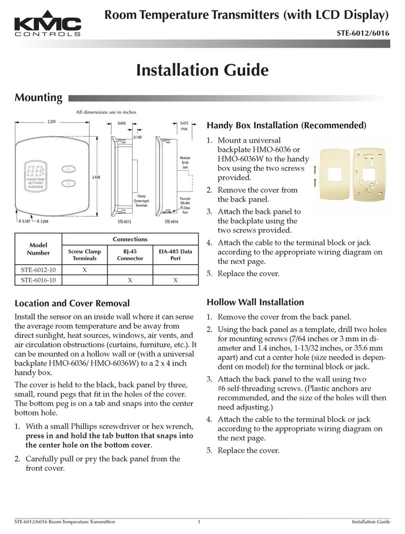
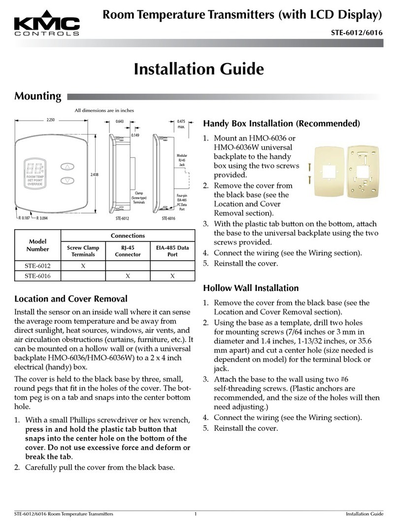
Handy Box Installation (Recommended)
1. MountanHMO-6036
wallplatetothehandy
boxusingthetwoscrews
provided.
2. RemovetheTHE-1102’s
coverfromtheblackbase
(seetheLocationand
CoverRemovalsection).
3. Withtheplastictabbuonontheboom,aach
thebasetothebackplateusingthetwoscrews
provided.
4. Connectthewiring(seetheWiringsection).
5. Reinstallthecover.
Hollow Wall Installation
1. RemovetheTHE-1102’scoverfromtheblackbase
(seetheLocationandCoverRemovalsection).
2. Usingthebaseasa
template,drilltwoholes
formountingscrews
(7/64inchesor3mmin
diameterand1.4inches,
1-13/32inches,or35.6mm
apart)andcutacenter
holefortheterminalblock.
3. Withtheplastictabbuonontheboom,aach
thebasetothewallusingtwo#6self-threading
screws.(Plasticanchorsarerecommended,and
thesizeoftheholeswillthenneedadjusting.)
4. Connectthewiring(seetheWiringsection).
5. Reinstallthecover.
Installation Guide
Humidity Transmitter w/ Temperature Sensor
THE-1102
Mounting
Mounting 1
Location and Cover Removal 1
Handy Box Installation (Recommended) 1
Hollow Wall Installation 1
Wiring 2
More Information 2
Maintenance 2
Important Notices 2
Location and Cover Removal
InstalltheTHE-1102onaninsidewallwhereitcan
sensetheaverageroomtemperature/humidityand
beawayfromdirectsunlight,heatsources,windows,
airvents,andaircirculationobstructions(curtains,
furniture,etc.).Itcanbemountedonahollowwall
or(withanHMO-6036)toa2x4inchhandybox.
Thecoverisheldtotheblackbasebythreesmall
pegsthattintheholesofthecover.Theboompeg
isonatabandsnapsintothecenterboomhole.
1. WithasmallPhillipsscrewdriverorhexwrench,
press in and hold the plastic tab buon that
snaps into the center hole on the boom of the
2-1/4" (57 mm)
2-7/16"
(62 mm)
5/8"
(16 mm)
Up (Toward Ceiling
at Installation)
Tab Button
Temperature Output
(10K Thermistor)
Humidity Output
(0 to 5 VDC)
Signal Ground
– Power Ground
(A)
(B)
(C)
(F)
(D) + 10 to 15 VDC Power
NOTE: The Thermistor
Temperature
Output
Terminal “A”
should be
at the top of
the terminal
strip aer
installation.
THE-1102 2 Installation Guide
© 2013 KMC Controls, Inc. 861-019-01F
KMC Controls, Inc.
19476IndustrialDrive
NewParis,IN46553
574.831.5250
www.kmccontrols.com;[email protected]
Important Notices
Thematerialinthisdocumentisforinformation
purposesonly. The contents and the product it de-
scribes are subject to change without notice. KMC
Controls, Inc. makes no representations or warran-
ties with respect to this document.Innoeventshall
KMCControls,Inc.beliableforanydamages,direct
orincidental,arisingoutoforrelatedtotheuseof
thisdocument.
Wiring
Maintenance
Carefulinstallationwillalsoensurelong-term
reliabilityandperformance.Removedustasneces-
saryfromholesintopandboom.Cleanwithaso,
dampclothandmildsoap.
More Information
Forcontrollercongurationofthe
humidity input,seetherelevant
documentationforthecontroller
andsoware.Forcontrollercon-
gurationofthethermistor input
aswellasmountingconsiderations,
troubleshooting,andotherinforma-
tion,seealsotherelevantsections
intheSTE-6010/6011/6013/6015
Application Guide.
ForTHE-1102specicationsand
accessoryinformation,seethe
THE-1102 Data Sheet.
Formoreinformationaboutusing
theTHE-1102withtheREE-2002,
seetheREE-2002 Installation
Guide.
NOTE: TheearlyversionoftheTHE-1102had
terminalsmarkedAthroughF.
Forpower,connectthe+sideofaregulated10–15
VDCpowersupplytoTerminal“D”andthe–sideto
“F”(seetheterminaldiagram).
NOTE: Signalgroundandpowergroundare
connectedtogetherinternally.
Connectthetemperatureoutput(10Kthermistor
acrossTerminals“A”and“C”)tothecontroller’s
temperatureinput.(Setthecontroller’spull-upresis-
toraccordingly.)
Connectthehumidityoutput(0to5VDCacross
Terminals“B”and“C”)tothecontroller’shumidity
input.(Setthecontroller’spull-upresistoraccord-
ingly.)
NOTE: Theinternalthermistorandthe0to5VDC
humidityoutputhaveacommonsignal
ground.
Alternately,useanREE-2002(shownherebutpur-
chasedseparately).SeetheREE-2002 Installation
Guideforadditionalinformationaboutpowerand
humidityoutputoptions.
REE-2002
24 VAC
GND
24 VAC
0-5 VDC
0-10
VDC
4-20
mA
F
C D
B
THE-1102
Humidity Output
(0-5 VDC)
(Without the REE-2002, only the THE-1102’s 0-5 VDC humidity
output and thermistor signal are available to a controller)
Temp. Output
(10K Thermistor)
Signal Ground
– Power Ground
+ 10-15 VDC Power
F
C
D
B
AController
Temp. Input
Signal Ground
Humidity Input*
+
Phase Neutral
*Load between Humidity Input and Signal Ground
is 250 ohms min. to 650 ohms max. for 4-20 mA
or 1000 ohms min. for VDC

Other KMC Controls Transmitter manuals

KMC Controls THE-1002 User manual

KMC Controls

KMC Controls THE-1002 User manual

KMC Controls TTE-1001 User manual

KMC Controls

KMC Controls TTE-1001 User manual

KMC Controls STE-6012-10 User manual

KMC Controls

KMC Controls STE-6012-10 User manual

KMC Controls STE-6012 User manual

KMC Controls

KMC Controls STE-6012 User manual

Popular Transmitter manuals by other brands

Warner RF FMT5.0-2U Series manual

Warner RF

Warner RF FMT5.0-2U Series manual

WT sensor PCM400 quick start guide

WT sensor

WT sensor PCM400 quick start guide

Questyle Audio T2 manual

Questyle Audio

Questyle Audio T2 manual

PulseAudio PA-TXMIX manual

PulseAudio

PulseAudio PA-TXMIX manual

Diehl IZAR RADIO EXTERN 434/868 PULSE installation guide

Diehl

Diehl IZAR RADIO EXTERN 434/868 PULSE installation guide

DHK Hobby D302 User instruction manual

DHK Hobby

DHK Hobby D302 User instruction manual

Lectrosonics UM400AV instruction manual

Lectrosonics

Lectrosonics UM400AV instruction manual

Emerson Rosemount MultiVariable 3051SMV quick start guide

Emerson

Emerson Rosemount MultiVariable 3051SMV quick start guide

Nautel XR12 installation manual

Nautel

Nautel XR12 installation manual

Becker Centronic SunWindControl SWC245A-II Assembly and operating instructions

Becker

Becker Centronic SunWindControl SWC245A-II Assembly and operating instructions

Dwyer Instruments 648B Series Installation and operating instructions

Dwyer Instruments

Dwyer Instruments 648B Series Installation and operating instructions

ACR Electronics ELT-201 EMERGENCY LOCATOR TRANSMITTER Product support manual

ACR Electronics

ACR Electronics ELT-201 EMERGENCY LOCATOR TRANSMITTER Product support manual

API DuoPak APD 2037 instructions

API

API DuoPak APD 2037 instructions

TESTO 0555 4444 instruction manual

TESTO

TESTO 0555 4444 instruction manual

Williams Sound WIR TX90 specification

Williams Sound

Williams Sound WIR TX90 specification

Zamel RNK-02 instruction manual

Zamel

Zamel RNK-02 instruction manual

DLO TuneStik DLZ62000 user manual

DLO

DLO TuneStik DLZ62000 user manual

Teradek BOLT 6 user manual

Teradek

Teradek BOLT 6 user manual

manuals.online logo
manuals.online logoBrands
  • About & Mission
  • Contact us
  • Privacy Policy
  • Terms and Conditions

Copyright 2025 Manuals.Online. All Rights Reserved.