SECTION SIX
// WARNING INDICATORS
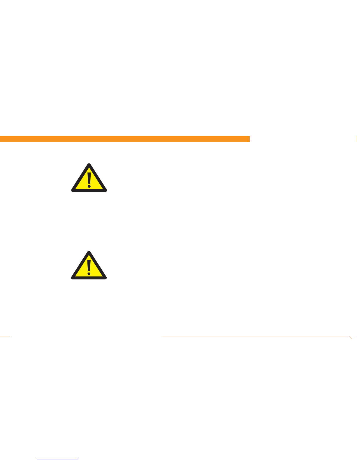
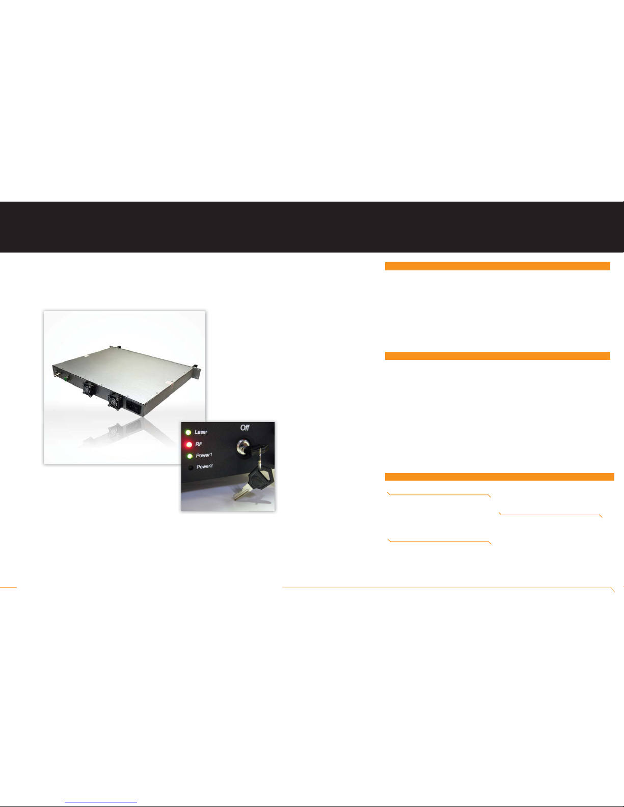
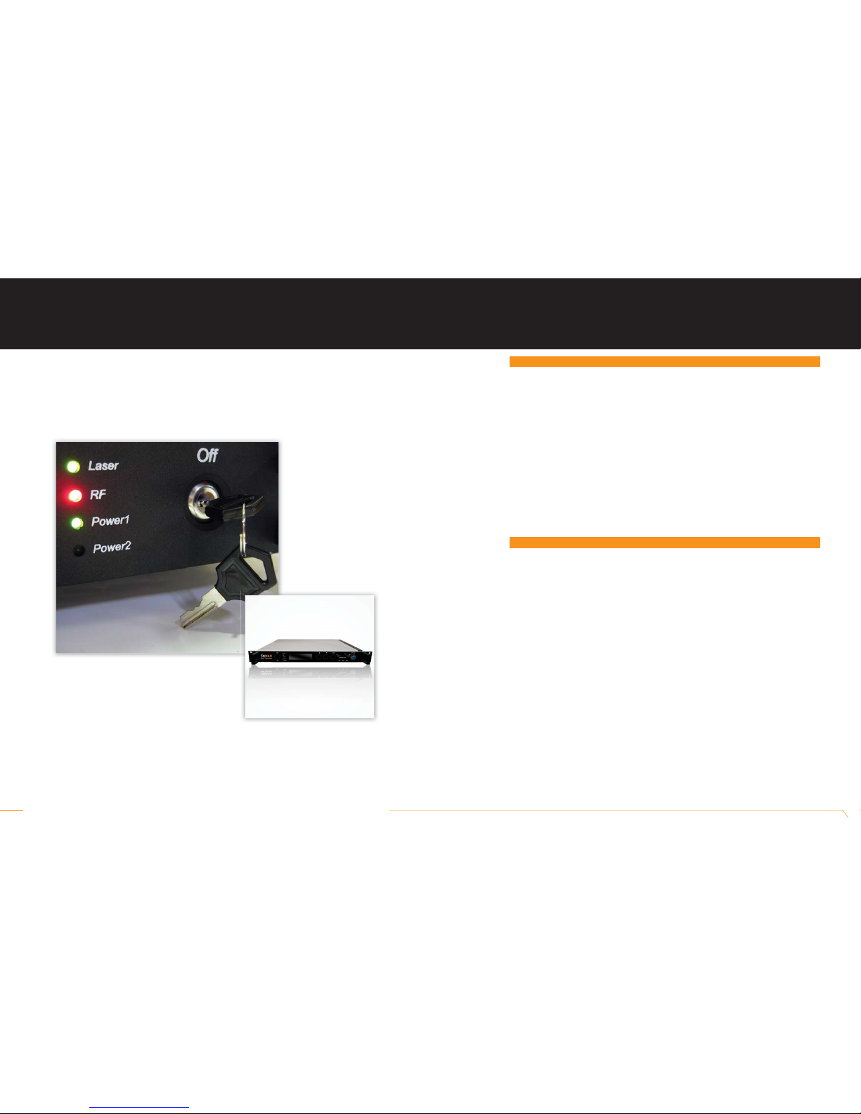
Taikan // 919 E. 29th St. Lawrence, KS 66046 // tel: 1-800-255-0247 // fax: 785-841-9512 // email: [email protected] // www.taikan.com 1550nm Transmitter | 15 TRANSMITTER
WORK
STATUS
> Present laser deflection is
low
> Present laser deflection is
high
> Laser temperature is high
> Laser output power is
locked
> Laser temperature is
locked
> Transmitter environment
temperature is low
> Transmitter environment
temperature is high
> Modulator deflected
> Modulator deflection float-
ing
> Transmitter inner tempera-
ture is high (1)
> Transmitter inner tempera-
ture is high (2)
> Transmitter interface
board temperature is low
STATUS DISPLAY
Warning: Lsr Bias Low
Warning: Lsr Bias Hi
Warning: Laser Temp Hi
Warning: Laser Pwr Lock
Warning: Laser Temp Lock
Warning: 1 temp (12) Lo
Warning: 1 temp (12) Hi
Warning: Modulator Bias
Warning: Mod Drift Hi
Warning: 1 temp (L)
Warning: Code #13c
Warning: Amb temp low
LED COLOR
RED
RED
RED
RED
RED
RED
RED
RED
RED
RED
RED
RED
EXPLANATION
Predicts the deflected circuit fault or laser aging. The
transmitter needs repair.
Predicts the deflected circuit fault or laser aging. The
transmitter needs repair.
Laser temperature is hovering from 25 °C. Check whether
the room temperature is still in the recommended range.
Continue to monitor the situation.
The laser output power has moved from the correct value
but the circuit is locked. Continue to monitor the situation.
Laser temperature control loop fault. Check the room
temperature and confirm whether it is still in the recom-
mended range. Continue to monitor the situation.
Optical transmitter environment temperature has moved
from 25 °C. Monitor the situation closely until the warning
light has disappeared.
Optical transmitter environment temperature has
moved from 25 °C. Monitor the status until the warning
disappears.
Modulator deflection point is close to maximum. Continue
monitoring. The deflection may need to be reset.
Modulator deflection point is close to the maximum.
Continue monitoring. The deflection may need to be reset.
Transmitter inner environment temperature is close to
limitation. Check the surrounding temperature and contin-
ue to monitor the device.
Transmitter inner environment temperature is close to
limitation. Check the surrounding temperature and con-
tinue monitoring.
Transmitter inner panel temperature is close to limitation.
Check the surrounding temperature and continue monitor-
ing the device.
TRANSMITTER
WORK
STATUS
> Transmitter interface board
temperature is high
> RF Input gain is low
> RF Input gain is high
> AGC circuit is not locked
> Fan fault
> Modulator drive gain is low
> Modulator drive gain is
high
STATUS DISPLAY
Warning: Amb temp high
Warning: RF Input Low
Warning: RF Input Hi
Warning: AGC Not Locked
Warning: Fan Failure
Warning: OMI Low
Warning: OMI Hi
LED COLOR
RED
RED
RED
RED
RED
RED
RED
EXPLANATION
Transmitter inner panel temperature is close to limita-
tion. Check the surrounding temperature and continue to
monitor the device.
RF input gain is close to minimum value of AGC. Check
the input gain & route. Continue monitoring
The input gain is close to the maximum value of AGC.
Check the input gain & route. Continue monitoring the
device.
RF input gain is close to margin. Adjust the input gain to
eliminate the warning. If the warning light remains on,
return the transmitter for repair
The rear fan is faulty. The transmitter needs to be
repaired.
The RF drive power entering the modulator is low. The
CNR performance can be improved by increasing OMI.
The RF drive power entering the modulator is high. The
distortion performance can be improved by decreasing the
OMI.
POSSIBLE RESOLUTIONS
I. Some of the warnings stated above can be resolved by restarting the power supply or pressing the “On/Off’ button on the front
panel. Please notify your Taikan representative if the warning indicator is still on.
II. To prevent any type of warning please follow these setup requirements:
>Ensure that the transmitter is placed in a temperature controlled environment of 0 °C ~ 50° C, that is also dust free.
> Make sure the transmitter is properly ventilated and allow ample space for the rear fan to work
> Check the power supply to confirm that it meets standard requirements. In addition check all connections are secure.
> Double check the changing of the RF gain.
> Keep the fiber connector clean.
III. The modulator deflector voltage warning can be resolved by resetting its deflection. To reset the deflection, press the “On/Off”
button and press it again to turn it on. It will take approximately 45 minutes for the transmitter to return to stable status. During this
period, the CSO value will be compromised, and the output and floating signal will decrease. This step should be carried out at a
time that would least affect your subscribers. Please contact your Taikan representative if this still does not resolve the situation.