PCCM MA-600 User manual

____________________________________________________________________________
VIDEO LVDS INTERFACE
AUDI A4 A5
WITHOUT MMI
VIDEO LVDS INTERFACE
AUDI A4 A5
SIN MMI
MA-600 PCCM
HW-VER.: 6.00 SW-VER.: 00 08.02.2010

__________________________________________________________________________________
__________________________________________________________________________________
PL UWAGA !! Koniecznie przeczy aj !!
1. Adapter ten odczytuje i konwertuje dane z magistrali CAN pojazdu. Nie gwarantujemy iż
wysyłane dane na magistralę CAN BUS nie spowoduj zakłóceń innych urz dzeń
elektronicznych w pojeździe. Jeśli montujesz dodatkowe urz dzenia, zawsze przestrzegaj
instrukcji montażu i warunków gwarancji producenta pojazdu – inaczej grozi Ci utrata
gwarancji.
2. Montaż i podł czenie powinno być wykonane przez odpowiednio wyszkolony personel.
3. Kable powinny być ułożone tak, aby nie zostały ściśnięte ani nacięte przez ostre metalowe
elementy. Nie instaluj urz dzenia w wilgotnych lub zakurzonych miejscach.
4. Nie otwieraj ani nie modyfikuj urz dzenia. Montuj i używaj tylko w pojazdach z instalacj
12V. Sprawdź zawsze czy bezpiecznik ma prawidłow wartość. Upewnij się, że poł czenia
s zrealizowane prawidłowo. Pamiętaj, że przepisy ruchu drogowego zabraniaj ogl dania
telewizji podczas jazdy samochodem.
5. ble ble nie odpowiadamy za wypadki
6. Za uszkodzenia spowodowane zł instalacj lub błędami w poł czeniach
elektrycznych lub szkody spowodowane z obu tych powodów producent nie ponosi
odpowiedzialności.
ES ATENCCION !! LEELO ANTES DE INSTALACION !!!
1. Este adaptador lee y convierte los datos de CanBus de vehiculo. No podemos
garantizar que los datos recopilados y enviados a Canbus no te provocaran
interferencias en otros unidades electronicas de vehiculo. Si montas aparatos
adiccionales en tu vehiculo siempre haz lo segun la descripcion y el manual del
fabricante de vehiculo – si no podras perder la garantia.
2. La instalacion debe ser realizada por un especialista.
3. Los cables siempre hay que colocar en los sitios sin humedad y sin riesgos que
puedan cortarse por algun elemento de caroseria o chapa.
4. No nos responsabilizamos de los accidentes occuridos en la instalacion
5. La conexion de interface exige conocimientos basicos de electronica. El fabricante
no se responsabiliza de los daños producidos por la incorecta instalacion de
interface
GB ATTENTION !! Read his necessary !!
1. This interface reads and converts data signals from the CAN protocol of a car.
Cannot guarantee that picking off data from the CAN BUS system may not
influence other electronic units or system in the car. If you install electronic units in
cars, please always pay attention to the installation – guides and the warranty –
regulations of the car producer because otherwise the warranty will be lost.
2. Installation and Connections need to be carried out by trained and well-informed
personnel.
3. Place the cables in such a way to avoid that they get folded or compressed by
sharp metal pieces. Do not install in humid or dusty locations.
4. Do NOT open or modify the appliance. Use the product only on vehicles having a
12V-battery. Make sure replacement fuses have the correct Amp.-value. Make
sure the connections are carried out correctly. Remember that Traffic Security
Rules DO NOT allow watching TV while driving the car.
5. jhfgi
6. For damages caused by wrong mounting /installation or mistakes of electrical
connection and damages caused by both reasons we are not available.
2

__________________________________________________________________________________
DE ACHTUNG !! Bi e lesen !!
1. Der Adapter liest und wertet die Daten vom CAN BUS aus. Wir garantieren nicht für
anfallende Störungen, wie z. B. defekte Elektroteile, die durch die verschickten Daten
hervorgerufen werden. Beim installieren von externen Geräten, folgen Sie bitte immer der
Montageanleitung vom Hersteller und deren Garantiebedingung. Bei Verstoß erlischt die
Garantie vorzeitig.
2. Installation und Verbindungen müssen vom gut informierten Fachmann vorgenommen
werden.
3. Kabel fernhalten von scharfkantigen Metall-Teilen, um ihr Verknicken oder Abtrennen zu
vermeiden. Nicht an feuchten oder staubigen Montagestellen installieren.
4. Das Gerät niemals auseinander nehmen oder Änderungen vornehmen. Das Produkt nur
auf Fahrzeugen verwenden, die über eine 12V-Batterie verfügen. Beim Austauschen der
Sicherungen immer auf den korrekten Ampere-Wert achten. Elektro-Verbindungen korrekt
vornehmen und kontrollieren. Das Verkehrsschutzgesetz verbietet das Fernsehen am
Steuer.
5. hjykttuyguikl
6. Für Schäden die durch Einbau oder Anschlussfehler und für Folgeschäden
übernehmen wir keine Haftung.
3

__________________________________________________________________________________
1.
PL Schemat podł czeń
ES Diagrama de conexion
GB Connection diagram.
DE Anschlussbild
4

__________________________________________________________________________
2.
PL SPECYFIKACJA
Wejścia :
- 1 x Analogowe RGB („Sync on Green” lub CSYNC)
-1 x CVBS (KAMERA WSTECZNA) wejście (obraz wymuszony)
-2 x A/V (NTST & PAL) wejścia
-1 x LCD wejście (z jednostki samochodowej)
Wyjścia :
-1 x CVBS wyjście (Video wyjście na monitory zagłówkowe)
-1 x Audio wyjście
-1 x LCD wyjście (do ekranu LCD )
Specyfikacja elektryczna.
-Napięcie zasilania : 10 VDC ~ 16 VDC
-Pobór mocy :7 WAT, Max
Przeł czanie wejść AV:
- Przez przycisk
-Możliwe pominięcie wejść AV podczas przeł czania trybu AV (wejść AV ) przez
odpowiedni konfigurację (patrz rozdział Konfiguracja)
ES ESPECIFICACIONES
Entradas :
- 1 x Analogicos RGB („Sync on Green” o CSYNC)
-1 x CVBS (KAMARA MARCHA ATRAS) entrada (pantalla forzada)
-2 x A/V (NTST & PAL) entradas
-1 x LCD entrada (de vehiculo)
Salidas :
-1 x CVBS salida (salidas Video para pantallas reposacabezas)
-1 x Audio salida
-1 x LCD salida (o para pantalla LCD )
Especificacion electrica
-Alimentacion : 10 VDC ~ 16 VDC
-Consumo :7 WAT, Max
Cambio conexiones AV:
- Atraves de interruptor
Hay posibilidad de cambio de entradas AV atraves de configuracion. Vea pagina
de cnfiguracion.
GB MAIN SPECIFICATION
Input :
- 1 x Analog RGB (Sync on Green or CSYNC)
-1 x CVBS (REAR CAMERA) Input (forced picture)
-2 x A/V (NTST & PAL) Inputs
-1 x LCD Input (Car system Input)
Output :
-1 x CVBS Output (Video Out for installing Headrest monitor)
-1 x Audio Output
-1 x LCD Output (LCD Operation)
Electric Power Spec.
-Input Power : 10 VDC ~ 16 VDC
-Consumption Power:7 WATT, Max
Switching AV Source
5

- By toggle switch
- Possible to skip AV source while switching Mode (AV source) by configuration
(Refer to the Configuration page)
__________________________________________________________________________
DE TECHNISCHE DATEN
Eingänge:
- 1 x Analog RGB (Sync on Green "oder CSYNC)
- 1 x FBAS (Reverse camera)-Eingang (Zwangs-Bild)
- 2 x A / V (PAL & NTST) Eintrag
- 1 x LCD-Eingang (Teiler)
Ausgänge:
- 1 x FBAS-Ausgang (Video-Ausgang, mit dem Rauchen Fahrzeug-Monitor)
- 1 x Audio-Ausgang
- 1 x LCD-Ausgang (für LCD)
Elektrische Spezifikationen.
- Spannungsversorgung: 10 VDC ~ 16 VDC
- Leistungsaufnahme: 7 WAT, Max
Schalt-AV-Eingänge:
- Mit dem Schlüssel
-Sie können zum AV-Modus beim Einschalten AV (AV-Eingang) von entsprechende
Konfiguration (siehe Abschnitt Konfiguration).
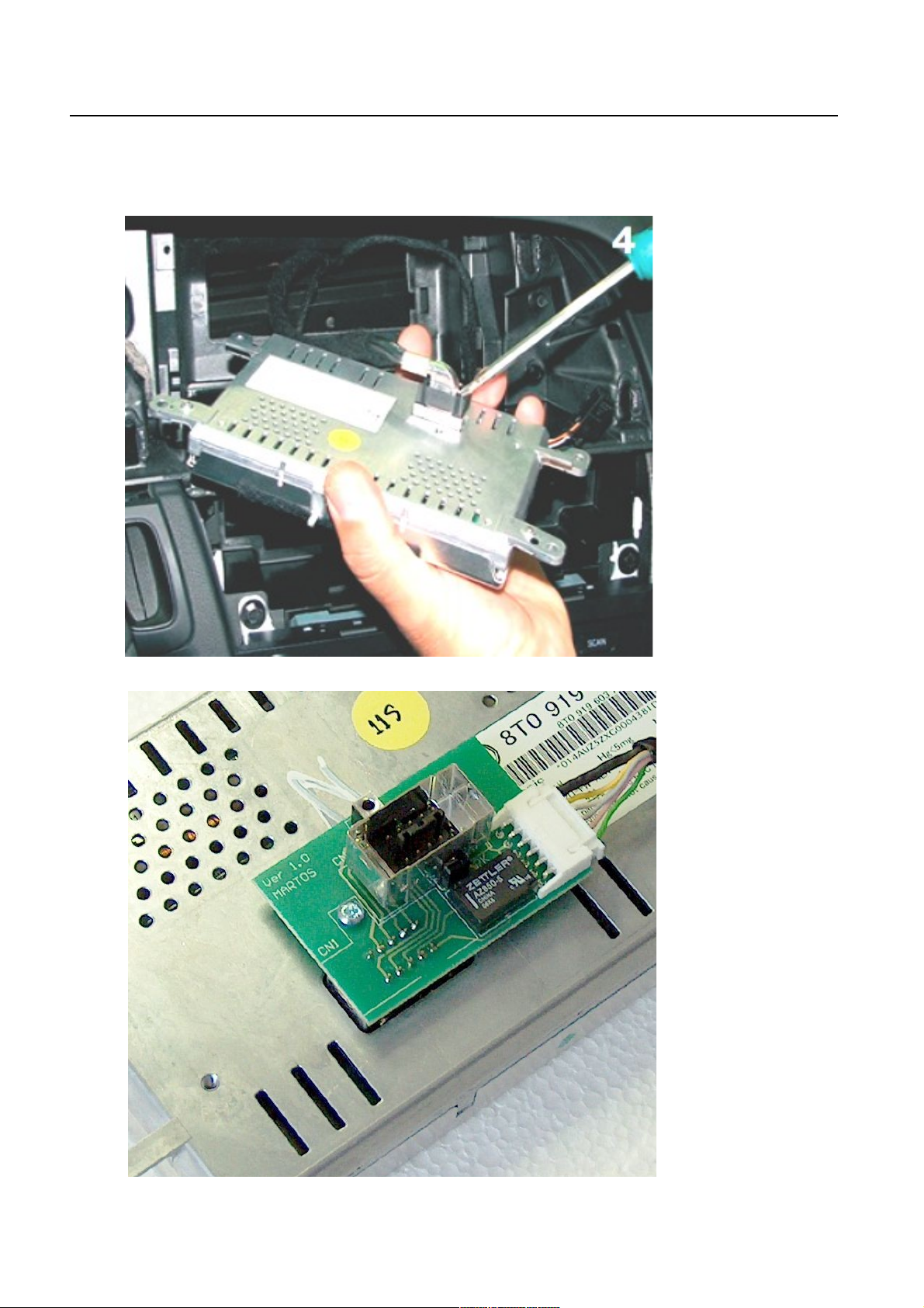
3.
PL Wyłącz zapłon i poczekaj 5 minu .
Zdemontuj i odł cz jednostkę główn .
ES Desconec a el encendido y espera 5 minu os.
Desmonta y desconecta unidad de control.
GB Turn off igni ion and wai 5 minu es.
Remove and disconnect the control unit.
DE Schal en Sie die Zündung und war en Sie 5 Minu en.
Entfernen Sie aus und Trennen Sie das Hauptgerät.
6

__________________________________________________________________________
__________________________________________________________________________
7
__________________________________________________________________________
5
8
__________________________________________________________________________
__________________________________________________________________________
6
4.
PL Podł cz okablowanie adaptera w kolejności (adap er musi być odłączony) :
Czarny – masa
Biały – CAN HIGH – rysunek poniżej
Brązowy – CAN LOW – rysunek poniżej. Przewody CAN podł cz równolegle do
istniej cych.
Czerwony – stały +12V.
Pozostałe kable podł cz według ich przeznaczenia
ES Conecta los cables de interface en siguiente orden (el in erface iene que es ar
desconec ado) :
Negro – masa
Blanco – CAN HIGH – segun el dibujo
Marron – CAN LOW – segun el dibujo. Los cables CAN conecta los en
paralelo con los existentes
ROJO – coriente continua +12V.
El resto de los cables conecta los segun para que van a ser utilizados
GB Connect the cables in order adapter (in erface mus be disconnec ed):
Black – ground negative
9
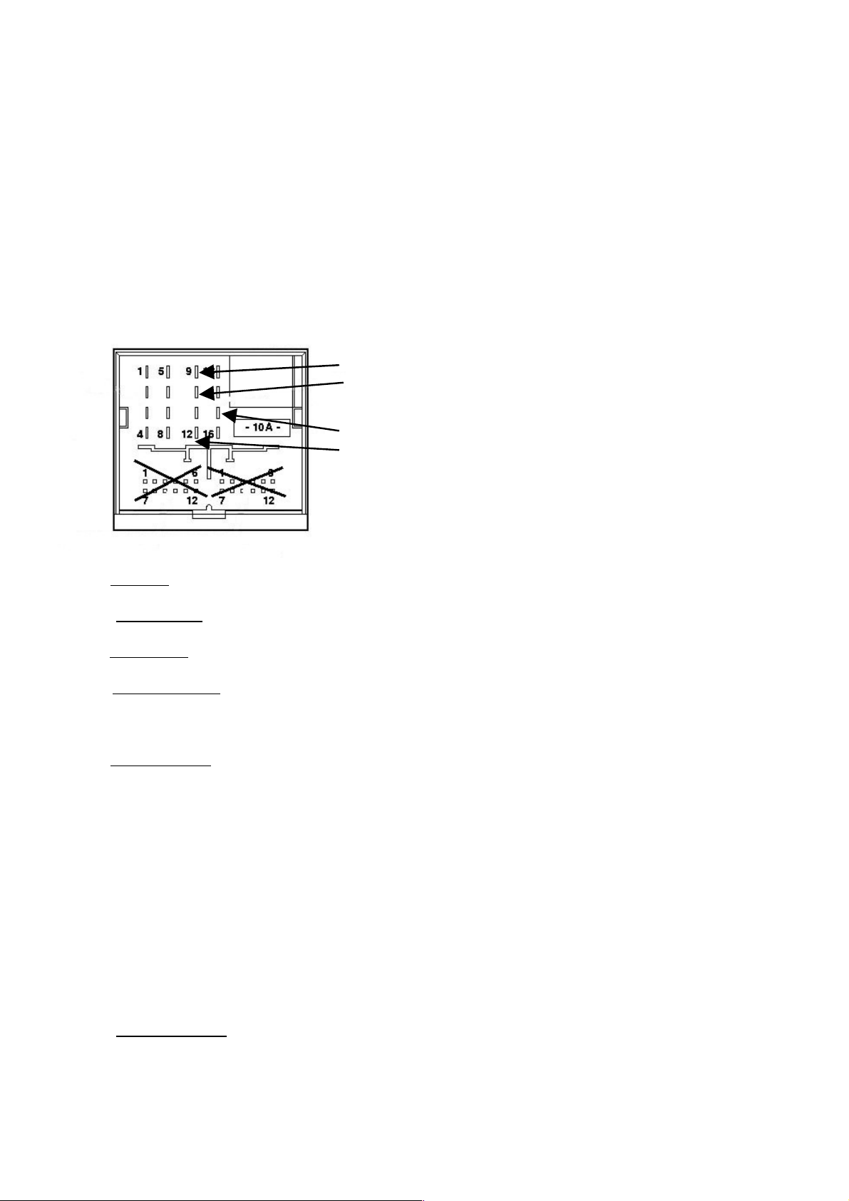
Whi e – to CAN HIGH – see picture below
Brown – to CAN LOW – see picture below. Connect CAN cables in parallel to the
existing.
Red – to +12V battery.
Other cables connect at their destination.
__________________________________________________________________________
DE Schließen Sie das Kabel um Adapter (Adap er muss ge renn ) :
Schwarz – an Masse
Weiß – an CAN HIGH PIN (s. Bild unten)
Braun – an CAN LOW PIN (s. Bild unten) Schließen Sie das CAN-Kabel parallel zu den
bestehenden .
Ro – Leitung an Dauerplus +12V.
Andere Kabel in Verbindung zu treten an ihrem Bestimmungsort
CAN HIGH – PIN 9
CAN LOW – PIN 10
BATTERY – PIN 15
GROUND – PIN 12
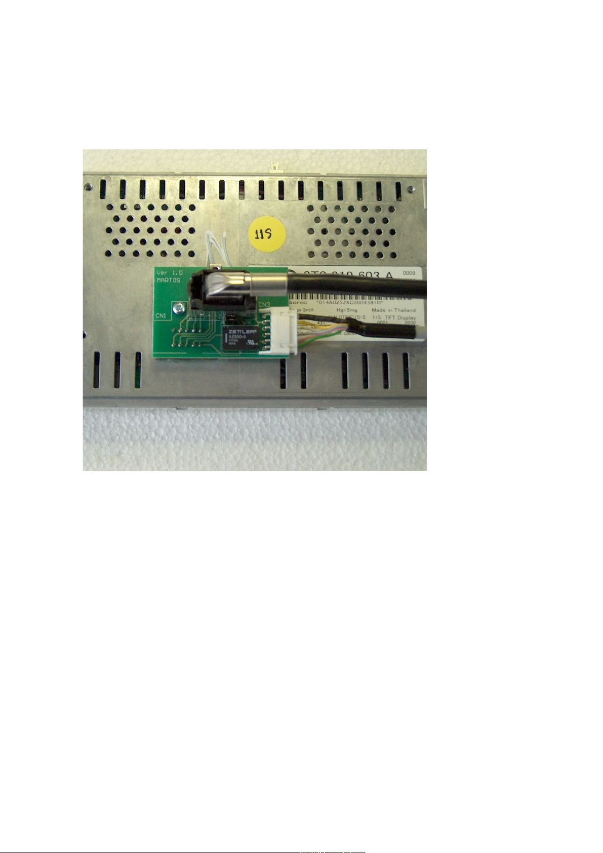
5.
PL Mon aż.
Podł cz wszystkie urz dzenia i zamontuj je w samochodzie.
ES Ins alacion.
Conecta todos los dispositivos i montalos en el vehiculo
GB Assembly.
Connect all the devices and mount them in the car.
DE Versammlung.
Schließen Sie alle Geräte und montieren sie in den Wagen.
6.
PL Konfiguracja.
Wł cz jednostkę główn . Naciśnij zewnętrzny przycisk a następnie klawisz MODE na
adapterze. Dalsze naciskanie MODE powoduje przejście do następnego trybu ustawień,
a wartość zmienia się klawiszami INCR i DECR. Cztery pierwsze tryby ustawiaj jakość
obrazu. Następne tryby ustawiaj odpowiednio:
AV1 – aktywne lub nieaktywne AV1
AV2 – aktywne lub nieaktywne AV2
VIDEO3 – aktywne lub nieaktywne VID3. Gdy VIDEO3 jest aktywne adapter nie reaguje
na bieg wsteczny i VID3 stanowi trzecie wejście video
CAM – aktywne lub nieaktywne. Gdy CAM jest w pozycji REV adapter reaguje na bieg
wsteczny i pokazuje obraz z wejścia VID3 na ekranie
ZOOM – nie dotyczy
ZOOM – nie dotyczy
YFM – ustala częstotliwość wbudowanego modulatora FM STEREO
ES Configuracion.
Enciende la unidad de control. Pulsa interruptor externo y despues MODE en el interface.
Pulsando mas el MODE entramos en siguiente cconfiguracion y los valores se modifican con
10

las teclas INCR i DECR . Los cuatro primeras configuraciones establecen calidad de pantalla
y los siguientes segun siguiente orden
AV1 – activo o desactivado AV1
AV2 – activo o desactivado AV2
VIDEO3 – activo o desactivado VID3. Si el VIDEO3 esta activo el interface no responde
A marcha atras y VID3 se establece como tercere entrada video
__________________________________________________________________________
CAM – activo o desactivado. Si el CAM esta en posicion REV el interface reaaciona a
marcha atras y muestra imagen de entrada VID3 en la pantalla.
ZOOM – sin aplicacion
ZOOM – sin aplicacion
YFM – configura la frecuencia de modulator FM STEREO
GB Configura ion
Turn on the main unit. Press external switch and then press the MODE button on the
adapter. Continue pressing the MODE to go to the next mode settings, and value changes
keys INCR and DECR. The first four modes set the image quality . The next set modes,
respectively:
AV1 – active or inactive AV1
AV1 – active or inactive AV2
VIDEO3 – active or inactive VID3. When the adapter is active VIDEO3 not respond to
signal the reverse and VID3 is the third video input.
CAM – active or inactive. When the CAM is in a position to respond to REV adapter
and the reverse shows the image the entry screen VID3
ZOOM – not applicable
ZOOM – not applicable
YFM – determine the frequency of the built FM-STEREO modulator.
DE Konfigura ion.
Schalten Sie das Hauptgerät. Externe drücken Sie die Taste und drücken Sie die MODE .
Halten Sie die MODE, um zum nächsten Mode-Einstellungen, Wert ändert sich durch Drücken
der INCR - und DECR-Taste. Die ersten vier Modi eingestellt, die Qualität Bild. Die nächsten
Modi, bzw.:
AV1 – aktiv oder nicht aktiv AV1
AV1 – aktiv oder nicht aktiv AV2
VIDEO3 – aktiv oder nicht aktiv VID3. Wenn der Adapter aktiv ist video3 antwortet nicht
rückgängig zu machen und VID3 ist das dritte Video-Eingang.
CAM – aktiv oder nicht aktiv. Wenn das CAM ist in der Lage, auf die REV-Adapter und
der Rückseite zeigt reagieren Bild der Eingabemaske VID3
ZOOM – nicht zutreffend
ZOOM – nicht zutreffend
YFM – bestimmen die Frequenz des FM gebaut Modulator-STEREO
11


__________________________________________________________________________
13

14
Table of contents
Other PCCM Automobile Accessories manuals


