PCCM MA-BOX2 User manual

UNIVERSAL MULTIMEDIA INTERFACE
VW - AUDI - MERCEDES
DVD PLAYER, DVB-T TUNER,
REAR VIEW CAMERA INPUT
MA-BOX2
HW-VER.: 4.00 SW-VER.: 05.05.2010

PL UWAGA !! Koniecznie przeczy aj !!
1. Adapter ten odczytuje i konwertuje dane z magistrali CAN pojazdu. Nie gwarantujemy iż
wysyłane dane na magistralę CAN BU nie spowodują zakłóceń innych urządzeń
elektronicznych w pojeździe. Jeśli montujesz dodatkowe urządzenia, zawsze przestrzegaj
instrukcji montażu i warunków gwarancji producenta pojazdu – inaczej grozi Ci utrata
gwarancji.
2. Montaż i podłączenie powinno być wykonane przez odpowiednio wyszkolony personel.
3. Kable powinny być ułożone tak, aby nie zostały ściśnięte ani nacięte przez ostre metalowe
elementy. Nie instaluj urządzenia w wilgotnych lub zakurzonych miejscach.
4. Nie otwieraj ani nie modyfikuj urządzenia. Montuj i używaj tylko w pojazdach z instalacją
12V. prawdź zawsze czy bezpiecznik ma prawidłową wartość. Upewnij się, że połączenia
są zrealizowane prawidłowo. Pamiętaj, że przepisy ruchu drogowego zabraniają oglądania
telewizji podczas jazdy samochodem.
5. Za uszkodzenia spowodowane złą instalacją lub błędami w połączeniach
elektrycznych lub inne szkody wynikłe po montażu adaptera producent nie ponosi
odpowiedzialności.
GB ATTENTION !! Read his necessary !!
1. This interface reads and converts data signals from the CAN protocol of a car. Cannot
guarantee that picking off data from the CAN BU system may not influence other
electronic units or system in the car. If you install electronic units in cars, please always
pay attention to the installation - guides and the warranty – regulations of the car producer
because otherwise the warranty will be lost.
2. Installation and Connections need to be carried out by trained and well-informed
personnel.
3. Place the cables in such a way to avoid that they get folded or compressed by sharp metal
pieces. Do not install in humid or dusty locations.
4. Do NOT open or modify the appliance. Use the product only on vehicles having a 12V-
battery. Make sure replacement fuses have the correct Amp.-value. Make sure the
connections are carried out correctly. Remember that Traffic ecurity Rules DO NOT allow
watching TV while driving the car.
5. For damage caused by poor installation or errors in the connections electrical or other
damage caused by the mounting adapter manufacturer shall not be liability.
DE ACHTUNG !! Bi e lesen !!
1. Der Adapter liest und wertet die Daten vom CAN BU aus. Wir garantieren nicht für
anfallende törungen, wie z. B. defekte Elektroteile, die durch die verschickten Daten
hervorgerufen werden. Beim installieren von externen Geräten, folgen ie bitte immer der
Montageanleitung vom Hersteller und deren Garantiebedingung. Bei Verstoß erlischt die
Garantie vorzeitig.
2. Installation und Verbindungen müssen vom gut informierten Fachmann vorgenommen
werden.
3. Kabel fernhalten von scharfkantigen Metall-Teilen, um ihr Verknicken oder Abtrennen zu
vermeiden. Nicht an feuchten oder staubigen Montagestellen installieren.
4. Das Gerät niemals auseinander nehmen oder Änderungen vornehmen. Das Produkt nur
auf Fahrzeugen verwenden, die über eine 12V-Batterie verfügen. Beim Austauschen der
icherungen immer auf den korrekten Ampere-Wert achten. Elektro-Verbindungen korrekt
vornehmen und kontrollieren. Das Verkehrsschutzgesetz verbietet das Fernsehen am
teuer.
5. Für chäden, die durch schlechte Montage oder Fehler in den Verbindungen verursacht
elektrische oder sonstige chäden, die durch die Installation des Adapter-Herstellers
entstehen, ist nicht Verantwortung.
2
1.
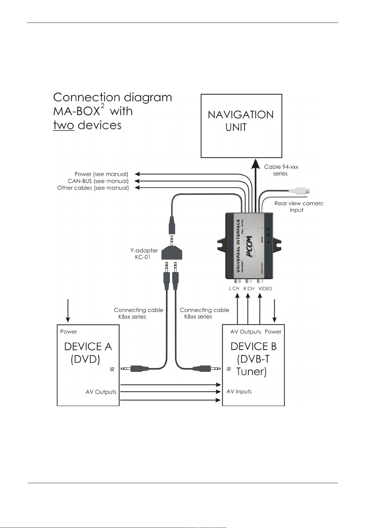
PL chematy podłączeń .
GB Connection diagrams.
DE Anschlussbilds
3

2.
PL Wyłącz zapłon i poczekaj 10 minu . Zdemontuj i odłącz nawigację.
GB Turn off igni ion and wai 10 minu es. Remove and disconnect the navigation system.
DE Schal en Sie die Zündung und war en Sie 10 Minu en. Entfernen ie aus und
Trennen ie die Navigation.
3.
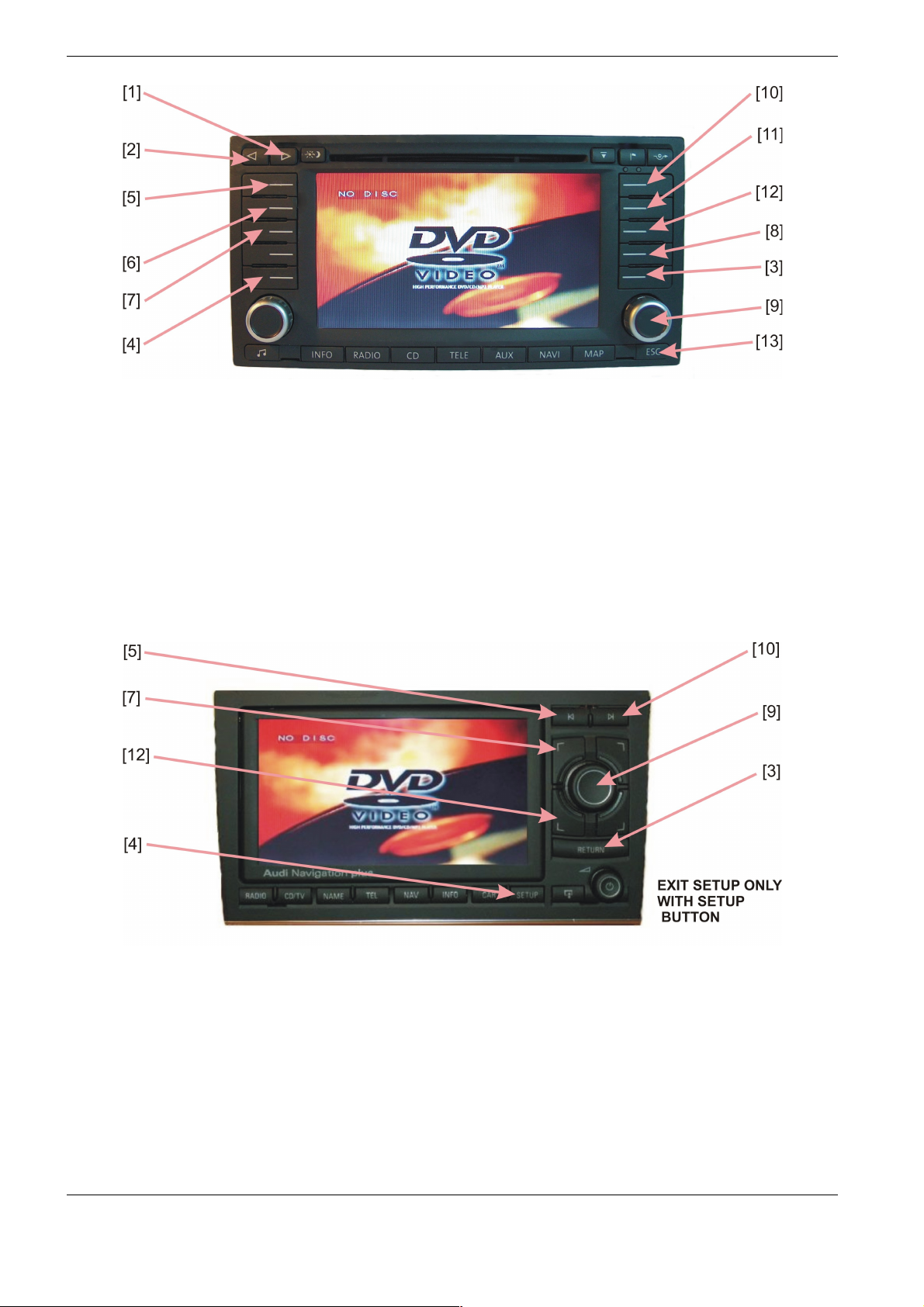
VW MFD, AUDI NAVIGATION PLUS , VW MFD2, RNS2, AUDI RNS-E:
PL Podłącz wtyk do nawigacji jak na zdjęciach poniżej.
GB Connect the connector into navigation system according to pictures below.
DE tecken ie den Adapterstecker wie auf den unteren Bilden dargestellt an die Navi .
4

VW MFD, AUDI NAVIGATION PLU VW MFD2, RN 2
AUDI RN -E
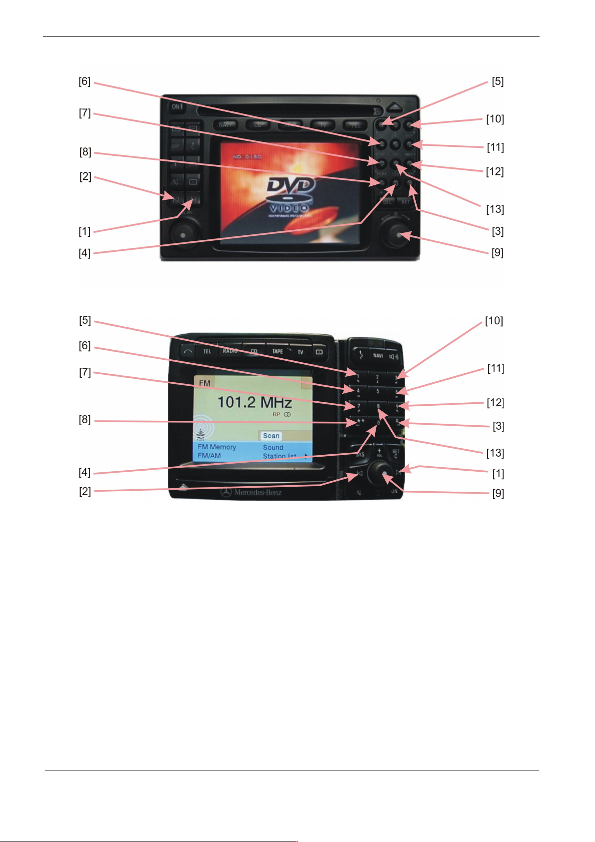
MB COMAND 2.0, APS220:
PL Podłącz obydwa wtyki do nawigacji jak na zdjęciu poniżej. Jeśli fabrycznie w te miejsca były
podłączone wtyki np. z sterowania kierownicą, przełóż piny z wtyku adaptera do wtyku
fabrycznego, zachowując odpowiednie numery w kostce
GB Connect multipin plug into navigation system according to picture below. In case the
places are occupied, take the pins from one connector to the other.
DE tecken ie die Adapterstecker wie auf dem Bild dargestellt an die Navi. Wenn die
Plätze belegt sind, müsse ie die Pins von einem tecker in das andere umbauen.
MB COMAND 2.5:
PL Podłącz czarny okrągły i czarny kwadratowy wtyk z tyłu nawigacji .
GB Connect the black round plug, and the black square plug in the rear of the Navigation system.
DE Einstecken ie die runden und die schwarzen rechteckigen tecker auf der Rückseite
Navigationssystems.
MB COMAND 2.0 MB COMAND 2.5
5

4.
PL Podłącz okablowanie adaptera w kolejności ( W yk musi być odłączony od adap era ! ) :
Czarny masa
Biały AUDI PLUS, MFD1, MFD2, RNS2, RNS-E - do CAN HIGH - rysunek poniżej.
COMAND 2.5 - do CAN LOW - rysunek poniżej.
Brązowy AUDI PLUS, MFD1, MFD2, RNS2, RNS-E - do CAN LOW – rysunek poniżej.
Żół y MB COMAND 2.5 - do CAN HIGH - rysunek poniżej.
Przewody CAN podłącz równolegle do istniejących.
Niebieski MFD1, MFD2, RNS2 - włącznik obrazu. Podanie na ten przewód +12V spowoduje
wymuszenie obrazu na nawigacji . Umożliwia to np. podgląd z kamery cofania.
Fiole owy doda kowy w yk – podanie na ten kabel +12V spowoduje automatyczne
przełączenie adaptera na sygnał z wejścia VIDEO2 (zależy od ustawień adaptera
– punkt 8 instrukcji).
Szary doda kowy w yk – po włączeniu nawigacji na kablu pojawia się napięcie +12V,
maks. 250mA (tylko gdy podłączona jest magistrala CAN)
Czerwony stały +12V.
GB Connect the cables in order adapter ( Plug mus be disconnec ed from adap er ! ):
Black ground negative
Whi e AUDI PLUS, MFD1, MFD2, RNS2, RNS-E - to CAN HIGH - see picture below.
COMAND 2.5 to CAN LOW - see picture below.
Brown AUDI PLUS, MFD1, MFD2, RNS2, RNS-E - to CAN LOW - see picture below.
Yellow COMAND 2.5 to CAN HIGH- see picture below.
Connect CAN cables in parallel to the existing.
Blue MFD1, MFD2, RNS2 Application to the wire +12 V will force the image on the
navigation. This makes possible to use the camera during the motion.
Purple ex ra plug – this is indicated on the +12 V cable will automatically switch on the
interface input signal Video2 (depends on the settings - point 8 this instruction).
Grey ex ra plug – when turn on of the navigation, on cable there is voltage 12 V, max
250mA (only when connected to the CAN bus)
Red to +12V battery.
DE chließen ie das Kabel um Adapter ( S ecker soll en ge renn werden von Adap er ! ) :
Schwarz an Masse
Weiß AUDI PLUS, MFD1, MFD2, RNS2, RNS-E - an CAN HIGH PIN (s. Bild unten)
COMAND 2.5 - an CAN LOW PIN (s. Bild unten)
Braun AUDI PLUS, MFD1, MFD2, RNS2, RNS-E - an CAN LOW PIN (s. Bild unten)
Gelb COMAND 2.5 - an CAN HIGH PIN (s. Bild unten)
Schließen Sie das CAN Kabel parallel zu den bestehenden.
Blau MFD1, MFD2, RNS2 - Aktivierung des Bildschirms. Durch das anschliessen
an +12V erfolgt die Umschaltung vom Navi auf den Bildschirm.
Viole ex ra S ecker – das ist auf der +12 V-Kabel angegeben wird automatisch chalter
auf dem Adapter Eingangssignal Video2 (hängt von den Einstellungen Adapter -
ein Punkt 8 Anleitung).
Grau ex ra S ecker – Navigation beim Einschalten des Kabel - gibt es 12 V,max.250mA
(wenn an den CAN-Bus angeschlossen)
Ro Leitung an Dauerplus +12V
6

5.
PL Do sterowania zewnętrznym urządzeniem użyj odpowiedniego kabla, zgodnie z opisem na
stronie 10 (sprzedawany oddzielnie). Do sterownia dwóch urządzeń użyj Y-adaptera KC01
(sprzedawany oddzielnie). Podłącz wtyk (wtyki) do wejścia “EXTERNAL REMONTE”
w DVD (w tunerze). Okablowanie DVD (tunera ) podłącz zgodnie z jego instrukcją.
GB To control an external device, use the appropriate cable, in accordance with described on
pages 10 (sold separately). To control two devices use the KC01 Y-adapter (sold separately).
Connect plug (plugs) to “EXTERNAL REMONTE” input in DVD-Player (TV-tuner). DVD’s
cables (tuner’s) connect according to his instruction.
DE Zur teuerung eine externen Quellen verwenden ie das dafür vorgesehenes und auf eite
10 beschriebene Kabel (nicht im Lieferumfang). Zur teuerung zweier externer Quellen
verwenden ie das dafür vorgesehene Y-Kabel - KC01 (nicht im Lieferumfang). chließen ie
den tecker an "EXTERNAL REMONTE" an den DVD-Player oder DVB-T Tuner an. Die
externen Geräte werden nach Hersteller vorgaben angeschloßen.
6.
PL Podłącz zasilanie do nawigacji i włącz ją. Podłącz teraz czarny wtyk do adaptera.
GB Connect the power supply to navigate and switch it on. Now connect the black plug into the
adapter.
DE chließen ie das Netzteil zu navigieren und schalten ie ihn ein. Nun verbinden ie den
schwarzen tecker in den Adapter.
7.
VW MFD, AUDI NAVIGATION PLUS:
PL W menu AUDIO wybierz opcję TV/VIDEO. Na ekranie będzie widoczny obraz. Dla AUDI
NAVIGATION PLU wystarczy wybrać źródło przyciskiem RADIO/CD/TV. Jeśli funkcja
TV/VIDEO jest niedostępna, odłącz wielopinowe złącze adaptera na moment.
GB Chose TV/VIDEO in AUDIO menu. It will be seen picture on the navi screen. For AUDI
NAVIGATION PLU chose video by pressing RADIO/CD/TV button. If TV/VIDEO mode is not
available, disconnect adapter’s multipin connector for moment.
DE Wählen ie im Menü Audio die Option TV/VIDEO oder bei Audi Plus drücken ie die Taste
RADIO/CD/TV. ie bekommen dann ein Bild zu sehen. Falls es nicht möglich ist, ziehen ie
kurzzeitig die Adapter tecker raus.
VW MFD2, RNS2:
PL W menu AUX wybierz opcję TV/VIDEO. Na ekranie będzie widoczny obraz
GB Chose TV/VIDEO in AUX menu. It will be seen picture on the navi screen.
DE In Menü AUX suchen ie die Option TV/VIDEO aus Bauen ie das Navi ein. Auf dem
Display erscheint das Bild.
7

MB COMAND 2.0, APS220:
PL Wybierz opcję TV. Na ekranie będzie widoczny obraz
GB Chose TV button. It will be seen picture on the navi screen.
DE Drücken ie die Option TV . Auf dem Display erscheint das Bild.
AUDI RNS-E:
PL Naciśnij przycisk CD/TV, pojawi się menu dostępnych źródeł. Naciśnij przycisk górna
strzałka i dużym pokrętłem wybierz opcję TV. Naciśnij pokrętło aby zatwierdzić.
GB Press the CD/TV key, the source menu will indicate. Press the upper right key and turning
rotary knob choose the TV option. For sign this, press rotary knob.
DE Nach dem ie die CD/TV taste gedrückt haben, erscheint das Quellen Menü. Danach drücken
ie die obere, rechte Pfeil Taste und mit dem Drehknopf erst wählen und dann
bestätingen ie die Funktion TV.
MB COMAND 2.5 :
PL Wybierz opcję TV. Zamontuj nawigację. Na ekranie będzie widoczny obraz
GB Chose TV button. Build the navi. It will be seen picture on the navi screen.
DE Drücken ie die Option TV aus Bauen ie das Navi ein. Auf dem Display erscheint das Bild.
8.
PL Adap ery z okablowaniem 94-210, 94-220, 94-130, 94-230, 94-140, 94-240,
94-150, 94-250 (z CAN-BUS):
Aby zaprogramować tryby pracy adaptera naciśnij i przytrzymaj klawisz na nawigacji ( nr [4] –
rysunki poniżej ). Na ekranie pojawi się symbol jasności. Każde krótkie naciśnięcie pokrętła
[9] zmienia opcję którą można regulować pokręcając pokrętłem:
Jasność -> Kon ras -> Nasycenie -> Urz. A -> Urz. B -> Zoom -> CAM -> Jasność i d.
Każda regulacja jest dostępna przez 10 sek. Po tym następuje wyjście z trybu regulacji.
Kody sterujące urządzeniami są podane na końcu instrukcji .
Funkcja CAM ma następujące ustawienia:
CAM 0 – wejście VIDEO 2 nieaktywne
CAM 1 – wejście VIDEO 2 wyzwalane przez +12V na fioletowym kablu
CAM 2 – TYLKO MFD2, RNS2, RNS-E wejście VIDEO 2 wyzwalane sygnałem biegu
wstecznego na magistrali CAN
Adap ery z okablowaniem 94-110, 94-120 (bez CAN-BUS) :
Wyreguluj jasność, kontrast i kolor za pomocą przycisków MODE,+ , - . na adapterze.
Naciskanie MODE powoduje wejście w tryby regulacji w kolejności : Jasność -> Kon ras ->
Nasycenie -> Urz. A -> Urz. B -> Zoom -> CAM -> Jasność i d. poprzez klawisze + i - .
Każda regulacja jest dostępna przez 10 sek. Po tym następuje wyjście z trybu regulacji.
Funkcja CAM ma następujące ustawienia:
CAM 0 – wejście VIDEO 2 nieaktywne
CAM 1 – wejście VIDEO 2 wyzwalane przez +12V na fioletowym kablu
CAM 2 – dla kabli 94-110 i 94-120 funkcja niedostępna
GB Adap ers wi h wiring harness 94-210, 94-220, 94-130, 94-230, 94-140, 94-240,
94-150, 94-250 (wi h CAN-BUS):
To program the adapter modes, press and hold button in the navigation (No [4] - the drawings
below). On the screen appears brightness symbol. Each short pressing the wheel [9] changes
the option that you can adjust the turning knob:
Brigh ness -> Con ras -> Sa ura ion -> Device A -> Device B -> Zoom -> CAM ->
Brigh ness, etc.
Each of regulation is posibble for 10sec. After this time adjustment is not available. Device
control codes are listed at the end of manual.
8

CAM function has the following settings:
CAM 0 - input VIDEO 2 inactive
CAM 1 - VIDEO 2 input triggered by a +12 V to purple cable
CAM 2 - ONLY MFD2, RNS2, RN -E VIDEO 2 input trigger back gear on the CAN BU
Adap ers wi h wiring harness 94-110, 94-120 (wi hou CAN-BUS) :
Adjust brightness, contrast and colour with a switch MODE, + , - at adapter. By pressing
MODE can adjust of order : Brigh ness -> Con ras -> Sa ura ion -> Device A -> Device B
-> Zoom -> CAM -> Brigh ness, etc. trought + , - Each of regulation is posibble for 10sec.
After this time adjustment is not available.
CAM function has the following settings:
CAM 0 - input VIDEO 2 inactive
CAM 1 - VIDEO 2 input triggered by a +12 V to purple cable
CAM 2 - for cables, 94-110 and 94-120 not available
DE Adap er mi der Verkabelung 94-210, 94-220, 94-130, 94-230, 94-140, 94-240,
94-150, 94-250 (mi CAN-BUS):
Um in das etup-Menü zu gelangen, halten ie die Gerätetaste Nr. [4] gedrückt (siehe Bild
unten). Auf dem Bildschirm erscheint die Helligkeit symbol. Durch Drücken des Drehknopfes
[9] können ie zwischen:
Helligkei –> Kon ras –> Sä igung –> Ex ern A –> Ex ern B –> Zoom –> CAM ->
Helligkei …. Wählen. Durch Drehen des Knopfes [9] können ie die diese Einstellungen
ändern. Nach 10 sec ohne Bedienung wird das etup-Menü verlassen. Control-Codes werden
am Ende des Unterrichts aufgeführt.
CAM-Funktion hat die folgenden Einstellungen:
CAM 0 - Eingang VIDEO 2 nicht aktiv
CAM 1 - VIDEO 2-Eingang von einem 12 V bis violett-Kabel ausgelöst
CAM 2 - NUR MFD2, RNS2, RNS-E VIDEO 2 - Eingang der Rückwärtsgang ignale zu den
CAN-BU
Adap er mi der Verkabelung 94-110, 94-120 (ohne CAN-BUS):
Durch Drücken auf die Taste MODE bei adapter können ie Helligkeit, Kontrast und
Farbe nacheinander wählen und mit den Tasten + und - einstellen. Wenn ie Innerhalb von
10 sec keine Taste drücken, ist die Einstellung beendet und gespeichert.
CAM-Funktion hat die folgenden Einstellungen:
CAM 0 - Eingang VIDEO 2 nicht aktiv
CAM 1 - VIDEO 2-Eingang von einem 12 V bis Violett-Kabel ausgelöst
CAM 2 - für Kabel, 94-110 und 94-120 nicht verfügbar
9.
PL Część rozkazów jest dostępna z klawiszy nawigacji. Pozostałe rozkazy do DVD (tunera) są
dostępne z oryginalnego pilota poprzez odbiornik podczerwieni. Zamiana pomiędzy
sterowaniem urządzeniem A i B następuje poprzez naciśnięcie i przytrzymanie pokrętła [9] .
GB ome of tuner commands are available from head unit. Rest of orders controlling DVD (tuner)
are available from original remote trough IR receiver. witching between the control device
A and B by pressing the and holding the rotary knob [9] .
DE Ein Teil der Befehle ist bedienbar vom Navi. Der Rest der Befehle zum DVD (Tuner) sind mit
der originalen Fernbedienung bedienbar , über Infrarotauge. Das Umschalten der teuerung
zwischen Ext A und Ext B erfolgt durch Drücken und Halten der Taste [9] des Gerätes..
9

Code number Operating device Connecting cable
1 DVD DIETZ, BOA85700 KB01
2 DVD MP410U, MP412U, MP420, DVP1000M, PHANTOM LIM KB01
3 DVD NE A1002, V T101, VDV402, CANVA KB01
4 DVD PHANTOM300B KB02
5 DVD BLAUPUNKT ME4 KB01
6 DVD PHONOCAR VM015 LIM KB02
7 HDD MEDIA BANK ME820AP KB01
8 DVB-T TUNER DVB-T2008 KB03
9 DVB-T TUNER DTR-1203EU KB04
10 DVB-T TUNER DVBTD50 KB05
11 DVB-T TUNER MDVT-0201, TVT2-DVB-0202 KB06
12 DVB-T TUNER DVB-T0101 KB07
13 DVB-T TUNER DVB-2009HD KB01
Number Opera ion DVD-Player Opera ion DVB-T Tuner O her Opera ion
[1] RIGHT VOL+
[2] LEFT VOL-
[3] PLAY/PAU E INFO
[4] ETUP ETUP ETUP* (Interface)
[5] BACK AV/DVB
[6] FA T BACKW. INFO
[7] LANGUAGE AUTO TORE
[8] TOP / POWER* EXIT / POWER*
[9] OK / UP / DOWN LI T / CH+ / CH- witch the devices*
[10] NEXT DVB / DAB
[11] FA T FORW. TEXT
[12] UBTITLE EPG
* - Press and hold for 4 seconds
10
Number Opera ion DVD-Player Opera ion DVB-T Tuner O her Opera ion
[1] RIGHT VOL+
[2] LEFT VOL-
[3] PLAY/PAU E INFO
[4] ETUP ETUP ETUP* (Interface)
[5] BACK AV/DVB
[6] FA T BACKW. INFO
[7] LANGUAGE AUTO TORE
[8] TOP EXIT
[9] OK / UP / DOWN LI T / CH+ / CH- witch the devices*
[10] NEXT DVB / DAB
[11] FA T FORW. TEXT
[12] UBTITLE EPG
[13] POWER POWER
* - Press and hold for 4 seconds
Number Opera ion DVD-Player Opera ion DVB-T Tuner O her Opera ion
[3] PLAY/PAU E EXIT
[4] ETUP ETUP ETUP* (Interface)
[5] BACK VOL-
[7] LANGUAGE / UP AV / DVB
[9] OK / LEFT / RIGHT LI T / CH+ / CH- witch the devices*
[10] NEXT VOL+
[12] UBTITLE / DOWN AUTO TORE
* - Press and hold for 4 seconds
11
Number Opera ion DVD-Player Opera ion DVB-T Tuner O her Opera ion
[1] RIGHT VOL+
[2] LEFT VOL-
[3] PLAY/PAU E INFO
[4] ETUP ETUP ETUP* (Interface)
[5] BACK AV/DVB
[6] FA T BACKW. INFO
[7] LANGUAGE AUTO TORE
[8] TOP EXIT
[9] OK / UP / DOWN LI T / CH+ / CH- witch the devices*
[10] NEXT DVB / DAB
[11] FA T FORW. TEXT
[12] UBTITLE EPG
[13] POWER POWER
* - Press and hold for 4 seconds
Technical support:
www.martos.com.pl
12
Other manuals for MA-BOX2
1
Other PCCM Automobile Accessories manuals


