PAGE 2 (314) 205-3033 WWW.DIODEDYNAMICS.COM
Scan the QR code to link to our installation video online!
NEED MORE HELP?
We’ve taken the time to test our products on your vehicle. We can guarantee
compatibility and tment the rst time – no guessing game! If you need more help
with installation, watch our step-by-step video to walk you through the process.
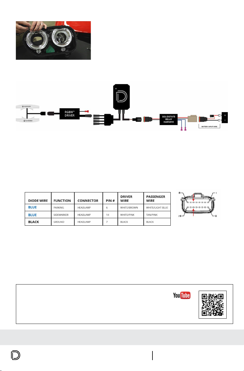
5. Connect the LED board to the RGBW driver. Then connect the driver to a Diode Dynamics LED
controller (sold separately).
8. Remove the Sidemarker and Parking pins or wires from the headlight harness, so they do not
go into the headlight. We recommend depinning the wires from the connector.
IMPORTANT: These are the original power wires for the factory LED. After replacing the factory LED, you
must disconnect these wires, or the vehicle will disable the signal.
9. Mount drivers, controller, and relay and tuck all wires. Drivers should be mounted outside
of headlight for serviceability, in a location away from the engine block to avoid excessive heat
buildup. Test thoroughly, reseal headlight, and reinstall onto vehicle.
Wiring Instructions
4. Using the alignment tabs and original screws, align
the ring and screw back down, securing the LED boards.
DO NOT OVERTIGHTEN. Replace the headlamp lens and
repeat for the other side.
IMPORTANT: DO NOT plug the LED panel directly into controller without the driver. The LEDs must be plugged
into driver rst to control the power.
Looking at face of vehicle
harness connector
DD2163 Challenger 2015 RGBWA LED Boards
This installation guide is for the following SKU:
PP0013B
PAGE 2 (314) 205-3033 WWW.DIODEDYNAMICS.COM
Scan the QR code to link to our installation video online!
NEED MORE HELP?
We’ve taken the time to test our products on your vehicle.
We can guarantee compatibility and tment the rst time – no
guessing game! If you need more help with installation, watch our
step-by-step video to walk you through the process.
5. Connect the LED board to the RGBW driver. Then connect the driver to a Diode Dynamics LED-
controller (sold separately).
6. Connect your controller to the SolidState Relay Harness. Connect the battery input wire
(included with Diode Dynamics RGBW Controller) to the harness. Run the battery input wire to
the battery and connect to the positive and negative battery terminals.
7. Tap the two blue wires from the
SolidState Relay Harness to your power
sources. In the table to the right, we have
listed the suggested wires to tap on the
headlight harness.
8. Remove the DRL and Parking pins or wires from the headlight
harness, so they do not go into the headlight. We recommend
depinning the wires from the connector. IMPORTANT: These are
the original power wires for the factory LED. After replacing
the factory LED, you must disconnect these wires, or the
vehicle will disable the signal.
9. Mount drivers, controller, and relay and tuck all wires. Drivers should be mounted
outside of headlight for serviceability, in a location away from the engine block to avoid excessive
heat buildup. Test thoroughly, reseal headlight, and reinstall onto vehicle.
DRIVER WIRE PASSENGER WIREPIN
PIN 6 - PARKING
PIN 14 - SIDEMARKER
WHITE/BROWN
WHITE/PINK
WHITE/LIGHT BLUE
TAN/PINK
Wiring Instructions
4. Using the alignment tabs and original screws, align
the ring and screw back down, securing the LED boards.
DO NOT OVERTIGHTEN. Replace the headlamp lens and
repeat for the other side.
RGBW
DRIVER
LED BOARD
LED BOARD
RGBW
CONTROLLER
SOLIDSTATE
RELAY
HARNESS
BATTERY INPUT WIRE
IMPORTANT: DO NOT plug the LED panel directly into controller without the driver. The LEDs must be plugged
into driver rst to control the power.
Looking at face of vehicle harness connector
PAGE 2 (314) 205-3033 WWW.DIODEDYNAMICS.COM
Scan the QR code to link to our installation video online!
NEED MORE HELP?
We’ve taken the time to test our products on your vehicle.
We can guarantee compatibility and tment the rst time – no
guessing game! If you need more help with installation, watch our
step-by-step video to walk you through the process.
5. Connect the LED board to the RGBW driver. Then connect the driver to a Diode Dynamics LED-
controller (sold separately).
6. Connect your controller to the SolidState Relay Harness. Connect the battery input wire
(included with Diode Dynamics RGBW Controller) to the harness. Run the battery input wire to
the battery and connect to the positive and negative battery terminals.
7. Tap the two blue wires from the
SolidState Relay Harness to your power
sources. In the table to the right, we have
listed the suggested wires to tap on the
headlight harness.
8. Remove the DRL and Parking pins or wires from the headlight
harness, so they do not go into the headlight. We recommend
depinning the wires from the connector. IMPORTANT: These are
the original power wires for the factory LED. After replacing
the factory LED, you must disconnect these wires, or the
vehicle will disable the signal.
9. Mount drivers, controller, and relay and tuck all wires. Drivers should be mounted
outside of headlight for serviceability, in a location away from the engine block to avoid excessive
heat buildup. Test thoroughly, reseal headlight, and reinstall onto vehicle.
DRIVER WIRE PASSENGER WIREPIN
PIN 6 - PARKING
PIN 14 -
SIDEMARKER
WHITE/BROWN
WHITE/PINK
WHITE/LIGHT BLUE
TAN/PINK
Wiring Instructions
4. Using the alignment tabs and original screws, align
the ring and screw back down, securing the LED boards.
DO NOT OVERTIGHTEN. Replace the headlamp lens and
repeat for the other side.
RGBW
DRIVER
LED BOARD
LED BOARD
RGBW
CONTROLLER
SOLIDSTATE
RELAY
HARNESS
BATTERY INPUT WIRE
IMPORTANT: DO NOT plug the LED panel directly into controller without the driver. The LEDs must be plugged
into driver rst to control the power.
Looking at face of vehicle harness connector
6. Connect your controller to the SolidState Relay Harness. Connect the battery input wire
(included with Diode Dynamics Sold-State Relay) to the harness. Run the battery input wire to
the battery and connect to the positive and negative battery terminals.
7. Tap the two blue wires from the SolidState Relay Harness and ground wire from the driver to
your power sources. In the table below, we have listed the suggested wires to tap on the
headlight harness.


