PCCM MA-BOX2 User manual

UNIVERSAL INTERFACE
MA-BOX
2
HW-VER.: 4.00 SW-VER.: 23 PL / GB / DE 05.05.2011

PL Dziękujemy za zakup produktu marki PCCM. Mamy nadzieję, iżnasz produkt spełni Wasze oczekiwania.
Prosimy przeczytaćinstrukcjęprzed pierwszym zamontowaniem i użyciem sprzętu.
GB Thank you for choosing a PCCM product. We hope that you will enjoy your new equipment. Please read these
instructions before you use the equipment for the first time.
DE Vielen Dank für den Kauf eines PCCM Produkt. Wir hoffen, dass unser Produkt Ihren Erwartungenentsprechen.
Bitte lesen Sie die Anweisungen, bevor Sie das Gerät zum ersten Mal verwenden.
PL UWAGA !! Koniecznie przeczytaj !!
1. Adapter ten odczytuje i konwertuje dane z magistrali CAN pojazdu. Nie gwarantujemy iżwysyłane dane na
magistralęCAN BUS nie spowodujązakłóceńinnych urządzeńelektronicznych w pojeździe. Jeśli montujesz
dodatkowe urządzenia, zawsze przestrzegaj instrukcji montażu i warunków gwarancji producenta pojazdu –
inaczej grozi Ci utrata gwarancji.
2. Montażi podłączenie powinno byćwykonane przez odpowiednio wyszkolony personel.
3. Kable powinny byćułożone tak, aby nie zostały ściśnięte ani nacięte przez ostre metalowe elementy. Nie instaluj
urządzenia w wilgotnych lub zakurzonych miejscach.
4. Nie otwieraj ani nie modyfikuj urządzenia. Montuj i używaj tylko w pojazdach z instalacją12V. Sprawdźzawsze
czy bezpiecznik ma prawidłowąwartość. Upewnij się, że połączenia sązrealizowane prawidłowo.
5. Za uszkodzenia spowodowane złąinstalacjąlub błędami w połączeniach elektrycznych lub inne szkody wynikłe
po montażu adaptera producent nie ponosi odpowiedzialności.
Pamiętaj, że przepisy ruchu drogowego zabraniająoglądania telewizji podczas jazdy samochodem.
GB ATTENTION !! Read this necessary !!
1. This interface reads and converts data signals from the CAN protocol of a car. Cannot guarantee that
picking off data from the CAN BUS system may not influence other electronic units or system in the car. If
you install electronic units in cars, please always pay attention to the installation - guides and the warranty
– regulations of the car producer because otherwise the warranty will be lost.
2. Installation and Connections need to be carried out by trained and well-informed personnel.
3. Place the cables in such a way to avoid that they get folded or compressed by sharp metal pieces. Do not
install in humid or dusty locations.
4. Do NOT open or modify the appliance. Use the product only on vehicles having a 12V-battery. Make sure the
connections are carried out correctly.
5. For damage caused by poor installation or errors in the connections electrical or other damage caused by
the mounting adapter manufacturer shall not be liability.
Remember that Traffic Security Rules DO NOT allow watching TV while driving the car.
DE ACHTUNG !! Bitte lesen !!
1. Der Adapter liest und wertet die Daten vom CAN BUS aus. Wir garantieren nicht für anfallende Störungen,
wie z. B. defekte Elektroteile, die durch dien verschickten Daten hervorgerufen werden. Beim installieren
von externen Geräten, folgen Sie bitte immer der Montageanleitung vom Hersteller und deren
Garantiebedingung. Bei Verstoß erlischt die Garantie vorzeitig.
2. Installation und Verbindungen müssen vom gut informierten Fachmann vorgenommen werden.
3. Kabel fernhalten von scharfkantigen Metall-Teilen, um ihr Verknicken oder Abtrennen zu vermeiden.Nicht
an feuchten oder staubigen Montagestellen installieren.
4. Das Gerät niemals auseinander nehmen oder Änderungen vornehmen. Das Produkt nur auf Fahrzeugen
verwenden, die über eine 12V-Batterie verfügen. Elektro-Verbindungen korrekt vornehmen und kontrollieren.
5. Für Schäden, die durch schlechte Montage oder Fehler in den Verbindungen verursacht elektrische oder
sonstige Schäden, die durch die Installation des Adapter-Herstellers entstehen, ist nicht Verantwortung.
Das Verkehrsschutzgesetz verbietet das Fernsehen am Steuer.
2

PL Schemat podłączenia
Uwaga! Tuner DVB-T powinien byćpodłączony jako urządzenie A
GB Connection diagrams.
Warning! DVB-T Tuner should always be connected as the device A
DE Schaltplan.
Achtung! DVB-T sollte als Gerät Aangeschlossen werden
PL Opcja:
Konfiguracja z dwoma
urządzeniami
GB Optional:
configuration with
two devices
DE Option:
Konfiguration mit
zwei geräten
Nawigacja / Navigation
Przewody bez funkcji sterowania
Connecting cables without control functions
Anschlussleitungen mit keine Steuerfunktionen
Przewody z funkcjąsterowania
Connectingcables with control function
Anschlussleitungen mit Steuerfunktion
AUDI Navi Plus 4:3 94-110 94-210
AUDI RNS-E 16:9 94-140 94-240
VW MFD1 94-110 94-210
VW MFD2 94-120 94-220
VW RNS 2 94-120 94-220
Mercedes COMAND 2.0 94-130 94-230
Mercedes COMAND APS220 94-130 94-230
Mercedes COMAND 2.5 94-150 94-250
Seat, Skoda Ford MFD1 94-110 94-210
3
PL Wyłącz zapłon i poczekaj 10 minut. Zdemontuj i odłącz nawigację.
GB Turn off ignition and wait 10 minutes. Remove and disconnect the navigation system.
DE Schalten Sie die Zündung und warten Sie 10 Minuten. Entfernen Sie aus und Trennen Sie die Navigation.
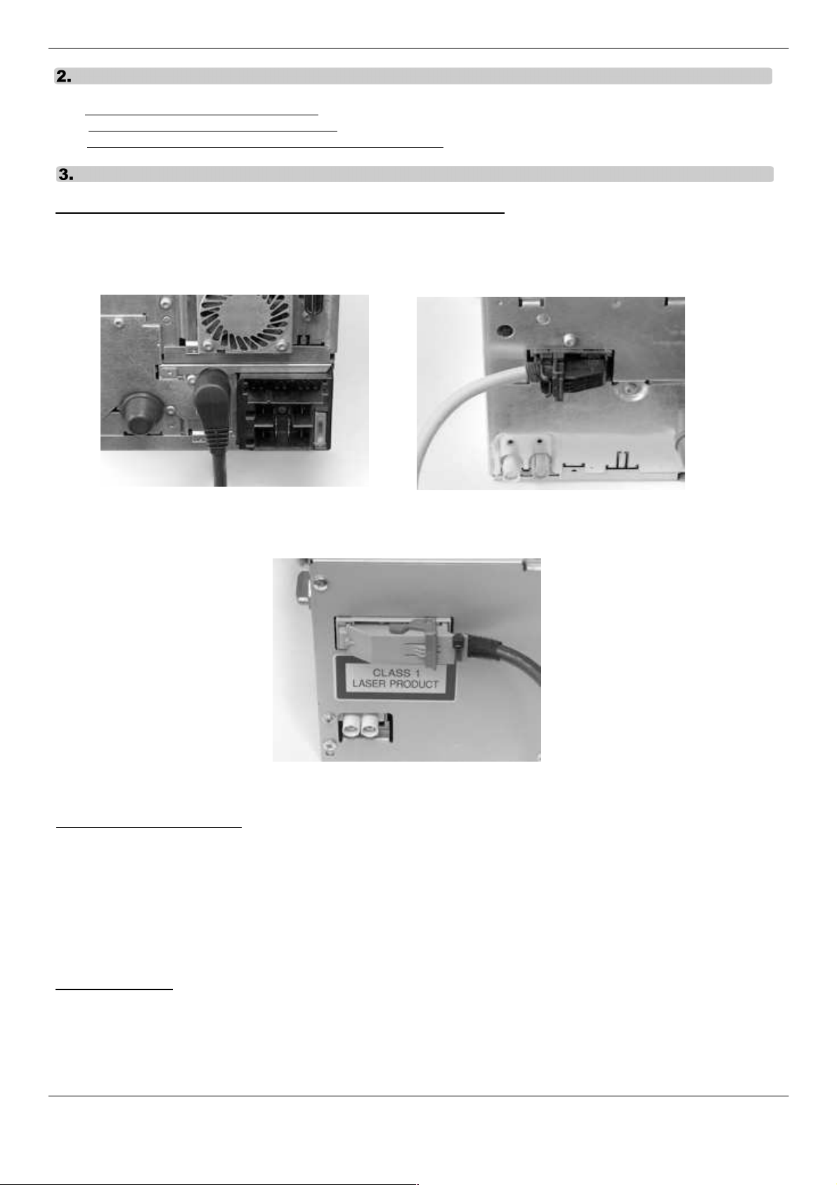
VW MFD, AUDI NAVIGATION PLUS , VW MFD2, RNS2, AUDI RNS-E:
PL Podłącz wtyk do nawigacji jak na zdjęciach poniżej.
GB Connect the connector into navigation system according to pictures below.
DE Stecken Sie den Adapterstecker wie auf den unteren Bilden dargestellt an die Navi.
VW MFD, AUDI NAVIGATION PLUS VW MFD2, RNS2
AUDI RNS-E
MB COMAND 2.0, APS220:
PL Podłącz obydwa wtyki do nawigacji jak na zdjęciu poniżej. Jeśli fabrycznie w te miejsca były podłączone wtyki
np. z sterowania kierownicą, przełóżpiny z wtyku adaptera do wtyku fabrycznego, zachowując odpowiednie
numery w kostce.
GB Connect multipin plug into navigation system according to picture below. In case the places are occupied, take
the pins from one connector to the other.
DE Stecken Sie die Adapterstecker wie auf dem Bild dargestellt an die Navi. Wenn die Plätze belegt sind, müsse
Sie die Pins von einem Stecker in das andere umbauen.
MB COMAND 2.5:
PL Podłącz czarny okrągły i czarny kwadratowy wtyk z tyłu nawigacji .
GB Connect the black round plug, and the black square plug in the rear of the Navigation system.
DE Einstecken Sie die runden und die schwarzen rechteckigen Stecker auf der Rückseite Navigationssystems.
4

MB COMAND 2.0 MB COMAND 2.5
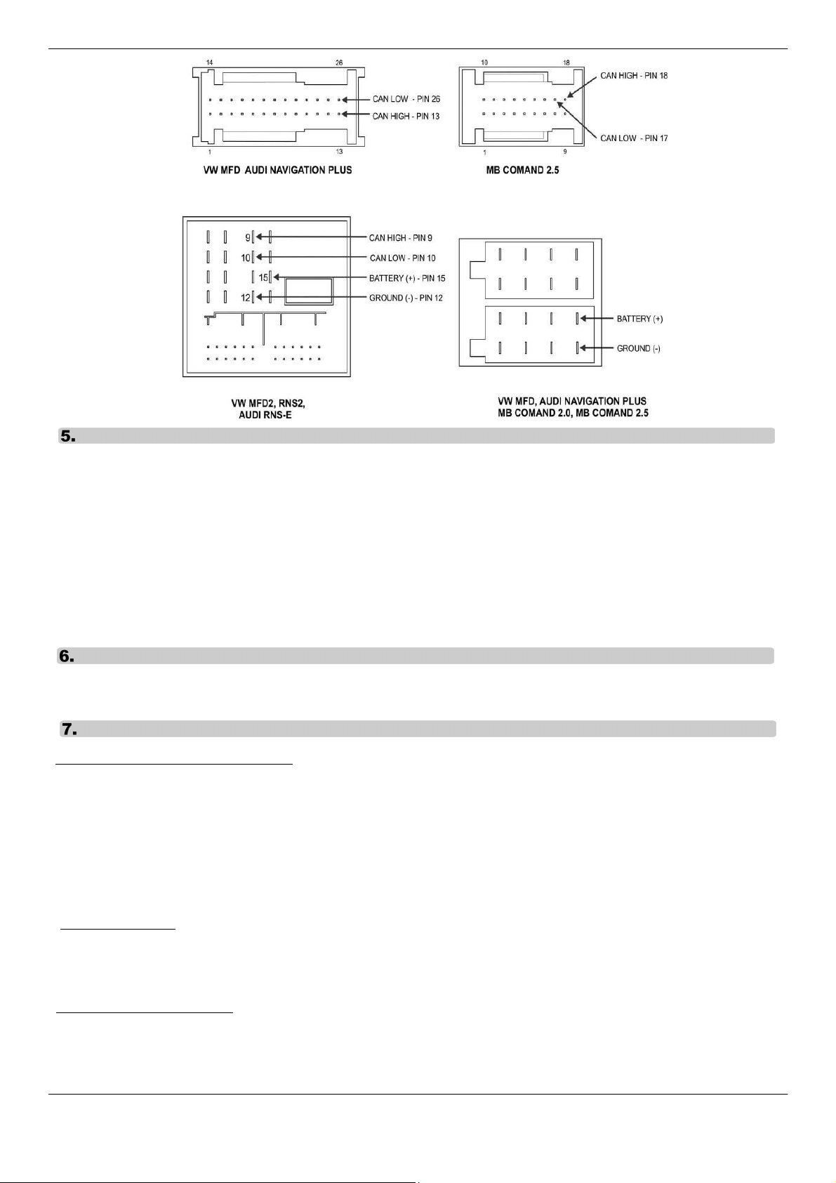
PL Podłącz okablowanie interfejsu w kolejności ( Wtyk musi byćodłączony od interfejsu ! ) :
Czarny masa
Biały AUDI PLUS, MFD1, MFD2, RNS2, RNS-E - do CAN HIGH - rysunek poniżej.
COMAND 2.5 - do CAN LOW - rysunek poniżej.
Brązowy AUDI PLUS, MFD1, MFD2, RNS2, RNS-E - do CAN LOW – rysunek poniżej.
Żółty MB COMAND 2.5 - do CAN HIGH -rysunek poniżej.
Przewody CAN podłącz równolegle do istniejących.
Niebieski MFD1, MFD2, RNS2 - włącznik obrazu. Podanie na ten przewód +12V spowoduje wymuszenie
obrazu na nawigacji . Umożliwia to np. podgląd z kamery cofania.
Zielony MB COMAND 2.0, COMAND 2.5 – Tv free. Funkcja dostępna poprzez przełącznik do masy
Fioletowy Podanie na ten kabel +12V spowoduje automatyczne przełączenie adaptera na sygnał z wejścia
VIDEO 2 (zależy od ustawieńadaptera – punkt 8 instrukcji).
Szary WYJŚCIE - po włączeniu nawigacji na kablu pojawia sięnapięcie +12V, maks. 250mA (tylko
gdy podłączona jest magistrala CAN)
Czerwony stały +12V.
GB Connect the cables from the inerface ( Plug must be disconnected from interface ! ):
Black ground negative
White AUDI PLUS, MFD1, MFD2, RNS2, RNS-E - to CAN HIGH - see picture below.
COMAND 2.5 to CAN LOW - see picture below.
Brown AUDI PLUS, MFD1, MFD2, RNS2, RNS-E - to CAN LOW - see picture below.
Yellow COMAND 2.5 to CAN HIGH- see picture below.
Connect CAN cables in parallel to the existing.
Blue MFD1, MFD2, RNS2 Application to the wire +12 V will force the image on the navigation. This
makes possible to use the camera during the motion.
Green MB COMAND 2.0, COMAND 2.5 - Tv free. Function available through the switch to ground.
Purple This is indicated on the +12 V cable will automatically switch interface input signal VIDEO 2
(depends on the settings - point 8 this instruction).
Grey OUTPUT - when turn on of the navigation, on cable there is voltage 12 V, max 250mA (only
when connected to the CAN BUS)
Red to +12V battery.
DE Schließen Sie das Kabel um Adapter ( Stecker sollten getrennt werden von Adapter ! ) :
Schwarz an Masse
Weiß AUDI PLUS, MFD1, MFD2, RNS2, RNS-E - an CAN HIGH PIN (s. Bild unten)
COMAND 2.5 - an CAN LOW PIN (s. Bild unten)
Braun AUDI PLUS, MFD1, MFD2, RNS2, RNS-E - an CAN LOW PIN (s. Bild unten)
Gelb COMAND 2.5 - an CAN HIGH PIN (s. Bild unten)
Schließen Sie das CAN-Kabel parallel zu den bestehenden.
Blau MFD1, MFD2, RNS2 - Aktivierung des Bildschirms. Durch das anschliessen an +12V erfolgt die
Umschaltung vom Navi auf den Bildschirm.
Grün MB COMAND 2.0, COMAND 2.5 Tv free Funktion zur Verfügung über den Schalter auf Masse
Violett extra Stecker – das ist auf der +12 V-Kabel angegeben wird automatisch Schalter auf dem
Adapter Eingangssignal VIDEO 2 (hängt von den Einstellungen Adapter - ein Punkt 8 Anleitung).
Grau extra Stecker – Navigation beim Einschalten des Kabel - gibt es 12 V, max.250mA (wenn an den
CAN-Bus angeschlossen)
Rot Leitung an Dauerplus +12V
5
PL
Do sterowania zewnętrznym urządzeniem użyj odpowiedniego kabla (sprzedawany oddzielnie), zgodnie z
opisem na stronie 8. Do sterownia dwóch urządzeńużyj Y-adaptera KC-02 (sprzedawany oddzielnie).
Podłącz wtyk (wtyki) do wejścia “EXTERNAL REMONTE” w DVD (w tunerze). Okablowanie DVD (tunera)
podłącz zgodnie z jego instrukcją.
GB To control an external device, use the appropriate cable (sold separately), in accordance with described on
pages 8. To control two devices use the KC02 Y-adapter (sold separately). Connect plug (plugs) to “EXTERNAL
REMONTE” input in DVD-Player (TV-tuner). DVD’s cables (tuner’s) connect according to his instruction.
DE Zur Steuerung eine externen Quellen verwenden Sie das dafür Kabel (nicht im Lieferumfang) vorgesehenes und
auf Seite 8 beschriebene . Zur Steuerung zweier externer Quellen verwenden Sie das dafür Y-Kabel - KC02
(nicht im Lieferumfang). Schließen Sie den Stecker an "EXTERNAL REMONTE" an den DVD-Player oder
DVB-T Tuner an. Die externen Geräte werden nach Herstellervorgaben angeschloßen.
PL Podłącz zasilanie do nawigacji i włącz ją. Podłącz teraz czarny wtyk do adaptera.
GB Connect the power supply to navigate and switch it on. Now connect the black plug into the adapter.
VW MFD, AUDI NAVIGATION PLUS:
PL W menu AUDIO wybierz opcjęTV/VIDEO. Na ekranie będzie widoczny obraz. Dla AUDI NAVIGATION PLUS
wystarczy wybraćźródło przyciskiem RADIO/CD/TV. Jeśli funkcja TV/VIDEO jest niedostępna, odłącz
wielopinowe złącze adaptera na moment.
GB Chose TV/VIDEO in AUDIO menu. It will be seen picture on the navi screen. For AUDI NAVIGATION PLUS
chose video by pressing RADIO/CD/TV button. If TV/VIDEO mode is not available, disconnect adapter’s
multipin connector for moment.
DE Wählen Sie im Menü Audio die Option TV/VIDEO oder bei Audi Plus drücken Sie die Taste RADIO/CD/TV. Sie
bekommen dann ein Bild zu sehen. Falls es nicht möglich ist, ziehen Sie kurzzeitig die Adapter Stecker raus.
VW MFD2, RNS2:
PL W menu AUX wybierz opcjęTV/VIDEO. Na ekranie będzie widoczny obraz
GB Chose TV/VIDEO in AUX menu. It will be seen picture on the navi screen.
DE In Menü AUX suchen Sie die Option TV/VIDEO aus Bauen Sie das Navi ein. Auf dem Display erscheint das Bild.
MB COMAND 2.0, APS220:
PL Wybierz opcjęTV. Na ekranie będzie widoczny obraz.
GB Chose TV button. It will be seen picture on the navi screen.
DE Drücken Sie die Option TV . Auf dem Display erscheint das Bild.
6

AUDI RNS-E:
PL Naciśnij przycisk CD/TV, pojawi sięmenu dostępnych źródeł. Naciśnij przycisk górna strzałka i dużym
pokrętłem wybierz opcjęTV. Naciśnij pokrętło aby zatwierdzić.
GB Press the CD/TV key, the source menu will indicate. Press the upper right key and turning rotary knob choose
the TV option. For sign this, press rotary knob.
DE Nach dem Sie die CD/TV taste gedrückt haben, erscheint das Quellen Menü. Danach drücken Sie die obere,
rechte Pfeil Taste und mit dem Drehknopf erst wählen und dann bestätingen Sie die Funktion TV.
PL W przypadku gdy na ekranie będąwidoczne zniekształcenia obrazu (nowa nawigacja RNS-E z ekranem HD)
naciśnij i przytrzymaj na 5 sekund przycisk '+' na adapterze, dopóki adapter sięnie zrestartuje.
GB In the case of distortion of the image (new AUDI RNS-E with HD display) , press '+' on the interface for about
5 seconds. Adapter reset and set new parameters of the image.
DE Im Fall der Verzerrung des Bildes (neu AUDI RNS-E mit HD-Display), drücken Sie '+' an der adapter für etwa
5 Sekunden. Adapter zurückgesetzt und neue Parameter des Bildes.
MB COMAND 2.5 :
PL Wybierz opcjęTV. Zamontuj nawigację. Na ekranie będzie widoczny obraz
GB Chose TV button. Build the navi. It will be seen picture on the navi screen.
DE Drücken Sie die Option TV aus Bauen Sie das Navi ein. Auf dem Display erscheint das Bild.
PL Adaptery z okablowaniem 94-210, 94-220, 94-130, 94-230, 94-140, 94-240, 94-150, 94-250 (z CAN-BUS)
Aby zaprogramowaćtryby pracy adaptera naciśnij i przytrzymaj klawisz na nawigacji ( nr [4] – rysunki poniżej ).
Na ekranie pojawi sięMENU. Każde krótkie naciśnięcie pokrętła [9] zmienia opcjęktórąmożna
regulowaćpokręcając pokrętłem: Kontrast →Jasność →Kolor →Zoom H →Urz. A →Urz. B →Kamera →
Zaciemnienie →Kontrast itd. Każda regulacja jest dostępna przez 10 sek. Po tym następuje wyjście z trybu
regulacji. Kody sterujące urządzeniami sąpodane na końcu instrukcji .
Funkcja Kamera ma następujące ustawienia:
CAMERA IN OFF - wejście VIDEO 2 nieaktywne
CAMERA IN 1 - wejście VIDEO 2 wyzwalane przez +12V na fioletowym kablu
CAMERA IN 2 - TYLKO MFD2, RNS2, RNS-E wejście VIDEO 2 wyzwalane sygnałem biegu wstecznego
na magistrali CAN
Adaptery z okablowaniem 94-110, 94-120 (bez CAN-BUS)
Wyreguluj jasność, kontrast i kolor za pomocąprzycisków MODE,+, -. na adapterze. Naciskanie MODE
powoduje wejście w tryby regulacji w kolejności: Kontrast →Jasność →Kolor →Zoom H →Urz. A →Urz. B
→Kamera →Zaciemnienie →Kontrast itd. poprzez klawisze +i -. Każda regulacja jest dostępna przez 10
sek. Po tym następuje wyjście z trybu regulacji.
Funkcja Kamera ma następujące ustawienia:
CAMERA IN OFF - wejście VIDEO 2 nieaktywne
CAMERA IN 1 - wejście VIDEO 2 wyzwalane przez +12V na fioletowym kablu
CAMERA IN 2 - dla kabli 94-110 i 94-120 funkcja niedostępna
GB Adapters with wiring harness 94-210, 94-220, 94-130, 94-230, 94-140, 94-240, (with CAN-BUS)
To program the adapter modes, press and hold button in the navigation No [4] - ( the drawings below). On the
screen appears MENU. Each short pressing the wheel [9] changes the option that you can adjust the turning
knob: Contrast →Brightness →Color →Zoom H →Device A →Device B →Camera in →Blending →
Contrast, etc. Each of regulation is posibble for 10sec. After this time adjustment is not available.
Device control codes are listed at the end of manual.
CAM function has the following settings:
CAMERA IN OFF - VIDEO 2 input inactive
CAMERA IN 1 - VIDEO 2 input triggered by a +12 V to purple cable
CAMERA IN 2 - ONLY MFD2, RNS2, RNS-E VIDEO 2 input trigger back gear on the CAN BUS
Adapters with wiring harness 94-110, 94-120 (without CAN-BUS)
Adjust brightness, contrast and colour with a switch MODE, +, -at adapter. By pressing MODE can adjust of
order : Contrast →Brightness →Color →Zoom H →Device A →Device B →Camera in →Blending →
Contrast, etc. trought +, -Each of regulation is posibble for 10sec. After this time adjustment is not available.
7

CAM function has the following settings:
CAMERA IN OFF - VIDEO 2 input inactive
CAMERA IN 1 - VIDEO 2 input triggered by a +12 V to purple cable
CAMERA IN 2 - for cables, 94-110 and 94-120 not available.
DE Adapter mit der Verkabelung 94-210, 94-220, 94-130, 94-230, 94-140, 94-240, 94-150, 94-25 (mit CAN-BUS)
Um in das Setup-Menü zu gelangen, halten Sie die Gerätetaste Nr. [4] gedrückt (siehe Bild unten). Auf dem
Bildschirm erscheint die MENU. Durch Drücken des Drehknopfes [9] können Sie zwischen: Kontrast →
Helligkeit →Sättigung →Zoom H →Extern A →Extern B →Kamera →Hintergrund →Kontrast Wählen.
Durch Drehen des Knopfes [9] können Sie die diese Einstellungen ändern. Nach 10 sec ohne Bedienung wird
das Setup-Menü verlassen. Control-Codes werden am Ende des Unterrichts aufgeführt.
CAM-Funktion hat die folgenden Einstellungen:
CAMERA IN OFF - Eingang VIDEO 2 nicht aktiv
CAMERA IN 1 - VIDEO 2-Eingang von einem 12 V bis violett-Kabel ausgelöst
CAMERA IN 2 - NUR MFD2, RNS2, RNS-E VIDEO 2 Eingang der Rückwärtsgang Signale zu den CAN BUS
Adapter mit der Verkabelung 94-110, 94-120 (ohne CAN-BUS)
Durch Drücken auf die Taste MODE bei adapter können Sie zwischen: Kontrast →Helligkeit →Sättigung →
Zoom H →Extern A →Extern B →CAM →Kontrast Wählen, und mit den Tasten +und - einstellen.
Wenn Sie Innerhalb von 10 sec keine Taste drücken, ist die Einstellung beendet und gespeichert.
CAM-Funktion hat die folgenden Einstellungen:
CAMERA IN OFF - Eingang VIDEO 2 nicht aktiv
CAMERA IN 1 - Eingang VIDEO 2 von einem 12 V bis violett-Kabel ausgelöst
CAMERA IN 2 - für Kabel, 94-110 und 94-120 nicht verfügbar
PL Część rozkazów jest dostępna z klawiszy nawigacji. Pozostałe rozkazy do DVD (tunera) sądostępne z
oryginalnego pilota poprzez odbiornik podczerwieni. Zamiana pomiędzy sterowaniem urządzeniem A i B
następuje poprzez naciśnięcie i przytrzymanie pokrętła [9]
.
Dodatkowo, podczas przełączania pomiędzy Ai B
generowany jest sygnał do tunera, powodujący przełączenie jego wejść AV.
GB Some of tuner commands are available from head unit. Rest of orders controlling DVD (tuner) are available
from original remote trough IR receiver. Switching between the control device Aand Bby pressing the and
holding the rotary knob [9] . In addition, when switching between Aand Bis generated signal for a TV tuner,
the tuner switch causes additional AV input
DE Ein Teil der Befehle ist bedienbar vom Navi. Der Rest der Befehle zum DVD (Tuner) sind mit der originalen
Fernbedienung bedienbar , über Infrarotauge. Das Umschalten der Steuerung zwischen Ext Aund Ext Berfolgt
durch Drücken und Halten der Taste [9] des Gerätes..
Kod urządzenia
Code number
Steuercode
Urzadzenie sterowane
Controlled device
Gesteuertes Gerät
Kabel połączeniowy
Connecting cable
Anschlusskabel
1 DVD DIETZ, BOA85700 KB-01
2 DVD MP10, MP412U, MP420, DVP1000M, PHANTOM SLIM KB-01
3 DVD NESA1002, VST101, VDV402, CANVA KB-01
4 DVD PHANTOM300B KB-02
5 DVD BLAUPUNKT ME4 KB-01
6 DVD PHONOCAR VM015 SLIM KB-02
7 HDD MEDIA BANK ME820AP KB-01
8 DVB-T TUNER DVB-T2008 KB-03
9 DVB-T TUNER DTR-1203EU KB-04
10 DVB-T TUNER DVBTD50 KB-05
11 DVB-T TUNER MDVT-0201, TVT2-DVB-0202 KB-06
12 DVB-T TUNER DVB-T0101 KB-07
13 DVB-T TUNER DVB-T2009HD KB-01
14 DVB-T TUNER DVB-T2010HD KB-08
15 DVB-T TUNER Phantom KB-09
16 DVD Ampire DVX101 KB-01
8

Number Operation DVD-Player Operation DVB-T Tuner Other Operation
[1] RIGHT VOL+
[2] LEFT VOL-
[3] PLAY/PAUSE INFO
[4] SETUP SETUP SETUP* (Interface)
[5] BACK AV/DVB
[6] FAST BACKW. INFO
[7] LANGUAGE AUTO STORE
[8] STOP / POWER * EXIT / POWER *
[9] OK / UP / DOWN LIST / CH+ / CH- Switch the devices *
[10] NEXT DVB / DAB
[11] FAST FORW. TEXT
[12] SUBTITLE EPG
* - Press and hold for 3 seconds
9

Number Operation DVD-Player Operation DVB-T Tuner Other Operation
[1] RIGHT VOL+
[2] LEFT VOL-
[3] PLAY/PAUSE INFO
[4] SETUP SETUP SETUP* (Interface)
[5] BACK AV/DVB
[6] FAST BACKW. INFO
[7] LANGUAGE AUTO STORE
[8] STOP EXIT
[9] OK / UP / DOWN LIST / CH+ / CH- Switch the devices *
[10] NEXT DVB / DAB
[11] FAST FORW. TEXT
[12] SUBTITLE EPG
[13] POWER POWER
* - Press and hold for 3 seconds
Number Operation DVD-Player Operation DVB-T Tuner Other Operation
[3] PLAY/PAUSE EXIT
[4] SETUP SETUP SETUP* (Interface)
[5] BACK VOL-
[7] LEFT/ LANGUAGE * LEFT / AUTOSTORE *
[9] OK / UP/ DOWN LIST / CH+ / CH- Switch the devices *
[10] NEXT VOL+
[12] RIGHT/ SUBTITLE * RIGHT / EPG *
* - Press and hold for 3 seconds
10

Number Operation DVD-Player Operation DVB-T Tuner Other Operation
[1] RIGHT VOL+
[2] LEFT VOL-
[3] PLAY/PAUSE INFO
[4] SETUP SETUP SETUP * (Interface)
[5] BACK AV/DVB
[6] FAST BACKW. INFO
[7] LANGUAGE AUTO STORE
[8] STOP EXIT
[9] OK / UP / DOWN LIST / CH+ / CH- Switch the devices *
[10] NEXT DVB / DAB
[11] FAST FORW. TEXT
[12] SUBTITLE EPG
[13] POWER POWER
* - Press and hold for 3 seconds
11
PL Proszęnie wyrzucaćurzadzeńelektronicznych do odpadów pochodzących z gospodarstw domowych !
Na podstawie Dyrektywy 2002/95/EC co do przedsięwzięć obowiązujących przy usuwaniu wysłużonych
urządzeńelektrycznych oraz elektronicznych, nasz produkt nie jest klasyfikowany jako odpad z gospodarstwa
domowego. Proszęoddaćgo do odpowiedniego punktu utylizacji odpadów w celu recyklingu. Co do sposobów
usuwania wysłużonych urzadzeńelektrycznych proszęsiędowiedziećw zarządzie Państwa gminy lub miasta.
GB Do not dispose of electrical appliances in household waste ! .
In accordance with European Directive 2002/96/EC on used electrical and electronic appliances and its
implementation in national law, used power tools must be collected separately and recycled in an ecologically
compatible manner. Please return the tool via the available collection facilities. Information on options for
disposing of electrical appliances after their useful life can be obtained from your local or city council.
DE Werfen Sie Elektrogeräte nicht in den Hausmüll !
Gemaß europäischen Richtlinie 2002/96/EC über Elektro-und Elektronik-Altgeräte ist unser Produkt nicht als
normaler Abfall eingestuft. Bitte senden Sie es an einem Sammelpunkt für das Recycling. Als Mittel zur
Verfügung getragen elektrische Geräte wenden Sie sich bitte bei Ihrer Gemeinde- oder Stadt.
PL Nasz produkt podlega przepisom dyrektywy RoHS, dotyczącej użycia substancji niebezpiecznych w sprzęcie
elektronicznym. Został zaprojektowany i wyprodukowany zgodnie z wymaganiami tej dyrektywy i nie zawiera
substancji niebezpiecznych dla zdrowia człowieka i środowiska naturalnego.
GB Our product is subject to the RoHS Directive on Hazardous Substances in electronic equipment. It was designed
and manufactured in accordance with the requirements of the directive and does not contain substances
dangerous for human health and the environment.
DE Unser Produkt ist unter die RoHS-Richtlinie über gefährliche Stoffe in elektronischen Geräten. Er war konstruiert
und gefertigt in Übereinstimmung mit den Anforderungen der Richtlinie und enthält keine Stoffe für die
menschliche Gesundheit und die Umwelt.
Technical support:
www.martos.com.pl
12
Other manuals for MA-BOX2
1
Other PCCM Recording Equipment manuals

Popular Recording Equipment manuals by other brands


Inter-m
Inter-m PX-6216 Operation manual

SMC Networks
SMC Networks EX12-SCM Series Operation manual

Carrier
Carrier KSAIC0301230 installation instructions

Hitachi
Hitachi ATW-KNX-01 quick start guide

elsner elektronik
elsner elektronik KNX B4 Universal Installation and adjustment

ETC
ETC Unison AV/Serial Interface v1.0.0 quick guide


